
Ausgabe/Edition:
04.2007
Printed in Germany
Änderungsindex
Rev. index: 0.0
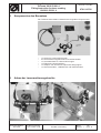
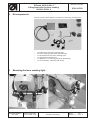
1. Komponenten des Bausatzes
Der Teilesatz 0910 590014 besteht aus folgenden Komponenten.
– 1 x Halter für Lasermarkierungen
– 3 x Lasermarkierungsleuchten mit Positionshalter
– 1 x Anschlußleiste für Lasermarkierungen
– 1 x Elektrische Anschlußdose
– 1 x Adapter zum Anschluss optionaler Baugruppen
– 1 x Satz Schrauben , Kabelbinder und Kabelschellen
2. Anbau der Lasermarkierungsleuchte
Anbauanleitung für Lasermarkierungsleuchten
Teilesatz 0910 59 001 4
Fitting Instruction for laser marking
Kit 0910 59 001 4
Teile-Nr./ Part-No.:
0791 910700
Blatt: von
Sheet: 1 from 8

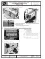
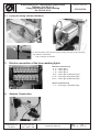
2.1. Verlegung der Leitungen und des Verteiler
Im Bereich der Luftleitung (sh. Pfeil) muss die hintere Abdeckhaube
nachgearbeitet werden.
– Mit einer Rundfeile etwas ausfeilen
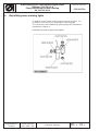
3. Elektrischer Anschluss der Lasermarkierungsleuchten
untere Klemmleiste
3- 4 = Laserleuchte 1
5- 6 = Laserleuchte 2
7- 8 = Laserleuchte 3
9-10 = Laserleuchte 4 (Nachrüstleuchte)
11-12 = Laserleuchte 5 (Nachrüstleuchte)
13-14 = Laserleuchte 6 (Nachrüstleuchte)
obere Klemmleiste
1- 2 = Laserleuchte 7 (Nachrüstleuchte)
4. Anschluss Adapter
Anbauanleitung für Lasermarkierungsleuchten
Teilesatz 0910 59 001 4
Fitting Instruction for laser marking
Kit 0910 59 001 4
Teile-Nr./ Part-No.:
0791 910700
Blatt: von
Sheet: 2 from 8
Printed in Germany
Änderungsindex
Rev. index: 0.0
Ausgabe/Edition:
04.2007

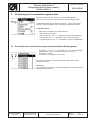
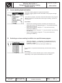
5. Aktivierung der Lasermarkierungsleuchten
Die Lasermarkierungen sind eine optionale Baugruppe.
Die Laser können den Programmnamen zugeordnet werden.
Im Beispiel sollen dem Programm “Riegel”, Laser zugeordnet
werden, die beim Nähen des Programms geschaltet werden.
Vorgehensw eise:
–
Maschine anschalten und referenzieren.
–
Obere Zeile [P: Riegel ].
–
“Service-Menue” mit “¯” anwählen und mit OK bestätigen.
–
“Korrekturen” mit “¯” anwählen und mit OK bestätigen.
–
“Laser/Ausgänge” mit “¯” anwählen und mit OK bestätigen.
5.1 Zuschalten einer Lasermarkierung zu einem bestimmten Nahtprogramm
–
Ausgang 1....7 mit “¯” auswählen und mit “OK” bestätigen.
(Der Zustand in der Anzeige wechselt von 0 auf 1)
0=inaktiv ; 1=aktiv
– Mit “ ESC” ins Hauptmenü wechseln.
Es können alle drei Lasermarkierungsleuchten gleichzeitig
betrieben werden.
Achtung !
Insgesamt k önnen bis zu 7 Markierungsleuchten angeschlossen
und geschaltet w erden.
Anbauanleitung für Lasermarkierungsleuchten
Teilesatz 0910 59 001 4
Fitting Instruction for laser marking
Kit 0910 59 001 4
Teile-Nr./ Part-No.:
0791 910700
Blatt: von
Sheet: 3 from 8
Ausgabe/Edition:
04.2007
Printed in Germany
Änderungsindex
Rev. index: 0.0

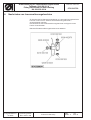
6. Nachrüsten von Lasermarkierungsleuchten
Zu den bereits im Bausatz enthaltenen 3 Lasermarkierungsleuchten
können noch bis zu 4 weitere Lasermarkierungsleuchten
angeschlossen werden.
Der Anschluss der Zusatzmarkierungsleuchten erfolgt w ie unter
Punkt 3 beschrieben.
Bausatz Zusatzmarkierungsleuchte 0510 590034
Anbauanleitung für Lasermarkierungsleuchten
Teilesatz 0910 59 001 4
Fitting Instruction for laser marking
Kit 0910 59 001 4
Teile-Nr./ Part-No.:
0791 910700
Blatt: von
Sheet: 4 from 8
Printed in Germany
Änderungsindex
Rev. index: 0.0
Ausgabe/Edition:
04.2007

Ausgabe/Edition:
04.2007
Änderungsindex
Rev. index: 0.0
Printed in Germany
1. Kit components
The set of parts 0910 590014 contains the following components:
– 1 x bracket for the laser marking light
– 3 x laser marking lights with mount holder
– 1 x terminal block for laser marking light
– 1 x electrical connector box
– 1 x adapter for connecting optional assemblies
– 1 x set of screws, cable tie and clamp
2. Mounting the laser marking light
Anbauanleitung für Lasermarkierungsleuchten
Teilesatz 0910 59 001 4
Fitting Instruction for laser marking
Kit 0910 59 001 4
Teile-Nr./ Part-No.:
0791 910700
Blatt: von
Sheet: 5 from 8

2.1. Laying the wiring and the distributor
In the proximity of the air duct (see arrow) the rear of the covering
cap must be reworked.
– File it using a r at-tail file.
3. Electric connection of the laser marking lights
Bottom t erminal strip
3- 4 = Laser light 1
5- 6 = Laser light 2
7- 8 = Laser light 3
9-10 = Laser light 4 (Retrofit light)
11-12 = Laser light 5 (Retrofit light)
13-14 = Laser light 6 (Retrofit light)
Upper terminal strip
1- 2 = Laser light 7 (Retrofit light)
4. Adapter Connection
Anbauanleitung für Lasermarkierungsleuchten
Teilesatz 0910 59 001 4
Fitting Instruction for laser marking
Kit 0910 59 001 4
Teile-Nr./ Part-No.:
0791 910700
Blatt: von
Sheet: 6 from 8
Ausgabe/Edition:
04.2007
Änderungsindex
Rev. index: 0.0
Printed in Germany

5. Laser marking light activation
The laser marking lights are optional assemblies.
The laser marking lights can be allocated to the program storage
location 1... 4.
In the above example, the laser should be allocated to the program
“Riegel”. It will then be switched on during the sewing process of
the program.
Procedure:
–
Switch on the s ewing machine and wait for the reference run.
–
Select the top line [P: Riegel] using the “” key and activate it by
pressing the “OK” key.
–
Select “Service-Menu” using the “¯” key and confirm it by
pressing the ”OK”key.
–
Select “Corrections” using the “¯” key and confirm it by pressing
the ”OK”key.
–
Select “Laser/Outputs” using the “¯” key and confirm it by
pressing the ”OK”key.
5.1 Switching on a laser marking in addition to a specified seam program
– Select the Output 1....7 using the “¯” key and confirm it by
pressing the ”OK” key (the status displayed switches from 0 to 1)
0=inactive ; 1=active
– Switch to the main menu by striking the “ESC ”key.
It is possible to operate simultaneously all three laser marking
lights.
Attention !
It is possible to c onnect and link up to 7 laser marking lights,
depending on the optional assemblies that are installed.
Anbauanleitung für Lasermarkierungsleuchten
Teilesatz 0910 59 001 4
Fitting Instruction for laser marking
Kit 0910 59 001 4
Teile-Nr./ Part-No.:
0791 910700
Blatt: von
Sheet: 7 from 8
Ausgabe/Edition:
04.2007
Änderungsindex
Rev. index: 0.0
Printed in Germany

6. Retrofitting laser marking lights
In addition to the 3 laser marking lights included in the kit, it is
possible to connect up to 4 further laser marking lights.
The connection of the additional marking lights are effected as
described in chapter 3.
Kit additional marking light 0510 590034
Anbauanleitung für Lasermarkierungsleuchten
Teilesatz 0910 59 001 4
Fitting Instruction for laser marking
Kit 0910 59 001 4
Teile-Nr./ Part-No.:
0791 910700
Blatt: von
Sheet: 8 from 8
Ausgabe/Edition:
04.2007
Änderungsindex
Rev. index: 0.0
Printed in Germany
-
 1
1
-
 2
2
-
 3
3
-
 4
4
-
 5
5
-
 6
6
-
 7
7
-
 8
8


in anderen Sprachen
- English: Duerkopp Adler 910 User manual
Verwandte Papiere
-
DURKOPP ADLER 510 Benutzerhandbuch
-
-
-
-
-
DURKOPP ADLER 176 Benutzerhandbuch
-
-
-
-