
DE
EN
NL
DA
FR
ES
IT
PL
FI
PT
SV
NO
TR
RU
UK
CS
ET
RO
BG
EL
04
06
08
10
12
14
16
18
20
22
24
26
28
30
32
34
36
38
40
42
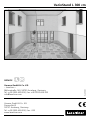
VarioStand L 300 cm
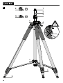
min. 98 cm
max. 300 cm
max. 310 cm
75°

02
A1
2
3
4!
1/4“
5/8“
5
7
6
8
9
10

VarioStand L 300 cm
03
B
1/4“5/8“
1.
2.
C
D
2.
1.
3.
G
3.
1.
4.
E
F
2.
1. 3.
2.

04
Funktion / Verwendung
Variables Kurbelstativ mit Wechseladapter zur Fixierung von Geräten mit 1/4“-
und 5/8“-Gewinde. Durch die speziellen Kombinationsspitzen (Gummi-Stahl-
spitzen) kann das Stativ an verschiedene Untergründe angepasst werden.
Lesen Sie die Bedienungsanleitung sowie die aktuellen Informationen
und Hinweise im Internet-Link am Ende dieser Anleitung vollständig
durch. Befolgen Sie die darin enthaltenen Anweisungen. Diese Unter-
lage ist aufzubewahren und bei Weitergabe des Gerätes mitzugeben.
!
– Setzen Sie das Gerät ausschließlich gemäß dem Verwendungszweck
innerhalb der Spezikationen ein.
– Vor Kindern unzugänglich aufbewahren.
– Baulich darf das Gerät nicht verändert werden.
– Setzen Sie das Gerät keiner mechanischen Belastung,
enormen Temperaturen oder starken Vibrationen aus.
– Bei Umbau in die Transportlage Quetschgefahr beachten.
– Nicht in ungesicherten Verkehrswegen aufstellen: Unfallgefahr
Allgemeine Sicherheitshinweise
– Feuchtigkeit und Sand möglichst vermeiden, nach Gebrauch gut reinigen.
– Das Stativ möglichst lotrecht auf festem Untergrund aufstellen: Kippgefahr.
– Auf Ausrichtung mit zentralem Schwerpunkt achten: Kippgefahr.
– Bei ungünstigen Windverhältnissen kann ein Zusatzgewicht zur Stabilisierung
angebracht werden (nicht im Lieferumfang).
– Nur geeignete Instrumente mit 1/4“ oder 5/8“ Anschluss bis zur maximalen
Traglast verwenden.
– Vor Transport oder Lagerung müssen Instrumente vom Stativ entfernt und
das Stativ in die Transportlage gebracht werden.
Hinweise zur Benutzung
1Aufnahme für
Gewindeadapter
2Stativ-Mittelsäule
3Verstellung der
Stativ-Mittelsäule
Gerätebeschreibung (siehe Abbildung A, Seite 02)
4Kurbelhub
5Fixierung Mittelsäule
6Schnellarretierung
zur Verstellung
der Stativbeine
DE
7Feststellschraube
zur Fixierung der
Stativbeine
8Gummi-Stahlspitzen
95/8“-Gewindeadapter
10 1/4“-Gewindeadapter

05
VarioStand L 300 cm
Technische Daten (technische Änderungen vorbehalten. 19W03)
max. Höhe 300 cm
min. Höhe 98 cm
max. Nutzlast 6 kg
Arbeitsbedingungen -20…60°C, Luftfeuchtigkeit max. 80% rH,
nicht kondensierend
Lagerbedingungen -20…70°C, Luftfeuchtigkeit max. 80% rH
Gewicht (ohne Adapter) 4,3 kg
Abmessung (B x H x T) 140 x 1000 x 140 mm
EU-Bestimmungen und Entsorgung
Das Gerät erfüllt alle erforderlichen Normen für den
freien Warenverkehr innerhalb der EU.
Weitere Sicherheits- und Zusatzhinweise unter:
http://laserliner.com/info?an=AHF
Anwendungshinweise
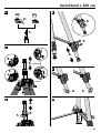
Wechseln der Gewindeadapter (siehe Abbildung B, Seite 03)
Verstellen der Mittelsäule (siehe Abbildung C und D, Seite 03)
Ausziehen der Stativbeine (siehe Abbildung E, Seite 03)
Kombinationsspitzen wechseln (siehe Abbildung F, Seite 03)
Stativbeine fixieren / lösen (siehe Abbildung G, Seite 03)
Hinweise zur Wartung und Pege
Reinigen Sie alle Komponenten mit einem leicht angefeuchteten Tuch und
vermeiden Sie den Einsatz von Putz-, Scheuer- und Lösungsmitteln. Lagern Sie
das Gerät an einem sauberen, trockenen Ort.
DE

06
Function / application
Variable crank tripod with adapter for mounting devices with 1/4" and 5/8"
thread. Thanks to the special rubber-steel combination tips the tripod can be
easily adapted to different surfaces.
Completely read through the operating instructions as well as the latest
information under the internet link at the end of these instructions.
Follow the instructions they contain. This document must be kept in a
safe place and passed on together with the device.
!
– The device must only be used in accordance with its intended
purpose and within the scope of the specications.
– Keep out of reach of children.
– The structure of the device must not be modied in any way.
– Do not expose the device to mechanical stress, extreme temperatures
or signicant vibration.
– Take care not to pinch your ngers when folding the tripod into
transport position.
– Do not set up the tripod on unsecured roads: risk of accident.
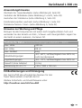
General safety instructions
– Avoid moisture and sand, clean thoroughly after use.
– Set up the tripod as perpendicular as possible on rm ground:
risk of toppling.
– Align to centre of gravity: risk of toppling.
– Under unfavourable wind conditions, an additional weight can be attached
to stabilise the tripod (not included in scope of delivery).
– Only use suitable instruments with 1/4“ or 5/8“ connection up to
the maximum load capacity.
– Before transporting or storing, instruments must be removed from
the tripod and the tripod folded into the transport position.
Instructions for use
1Mount for thread
adapter
2Centre column
3Adjustment of
the centre tripod
column
Device description (see Fig. A, page 02)
4Crank height adjustment
5Fixing the centre column
6Quick-release lock for
adjusting the tripod legs
7Locking screw
for fixing the tripod legs
EN
8Rubber-steel tips
95/8“ thread adapter
10 1/4“ thread adapter

07
VarioStand L 300 cm
To change the thread adapter (see Fig. B, Page 03)
To adjust the centre column (see Fig. C and D, Page 03)
To extend the tripod legs (see Fig. E, Page 03)
To change the combination tips (see Fig. F, Page 03)
Locking/releasing tripod legs (see Fig. G, Page 03)
EU directives and disposal
This device complies with all necessary standards
for the free movement of goods within the EU.
Further safety and supplementary notices at:
http://laserliner.com/info?an=AHF
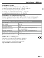
Technical data (Subject to technical alterations. 19W03)
Max. height 300 cm
Min. height 98 cm
Max. load capacity 6 kg
Operating conditions -20…60°C, max. humidity 80% rH,
no condensation
Storage conditions -20…70°C, max. humidity 80% rH
Weight (not including adapter) 4,3 kg
Dimensions (W x H x D) 140 x 1000 x 140 mm
Information on use
Information on maintenance and care
Clean all components with a damp cloth and do not use cleaning agents,
scouring agents and solvents. Store the device in a clean and dry place.
EN
8Rubber-steel tips
95/8“ thread adapter
10 1/4“ thread adapter

VarioStand L 300 cm
SERVICE
Umarex GmbH & Co. KG
– Laserliner –
Möhnestraße 149, 59755 Arnsberg, Germany
Tel.: +49 2932 638-300, Fax: +49 2932 638-333
info@laserliner.com
Umarex GmbH & Co. KG
Donnerfeld 2
59757 Arnsberg, Germany
Tel.: +49 2932 638-300, Fax: -333
www.laserliner.com
Rev19W03
-
 1
1
-
 2
2
-
 3
3
-
 4
4
-
 5
5
-
 6
6
-
 7
7
-
 8
8


