
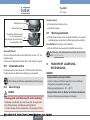
Quickstart
English Deutsch Français
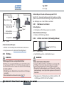
Type 2301
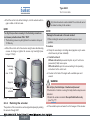
2/2-way globe control valve
2/2-Wege-Geradsitzregelventil
Vanne de réglage à siège droit 2/2 voies

We reserve the right to make technical changes without notice.
Technische Änderungen vorbehalten.
Sous réserve de modifications techniques.
© 2008-2015 Bürkert Werke GmbH
Operating Instructions 1502/02_EU-ML_00810302 / Original DE

3
Quickstart
1 QUICKSTART ..................................................................................................3
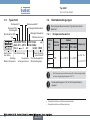
2 SYMBOLS .........................................................................................................4
3 INTENDED USE .............................................................................................4
4 BASIC SAFETY INSTRUCTIONS ..........................................................5
5 GENERAL INFORMATION ........................................................................6
6 STRUCTURE AND FUNCTION...............................................................6
7 TECHNICAL DATA ........................................................................................7
8 INSTALLATION ............................................................................................10
9 PACKAGING, TRANSPORT, STORAGE ..........................................16
Type 2301
1 QUICKSTART
The operating instructions describe the entire life cycle of the device.
Keep these instructions in a location which is easily accessible to
every user and make these instructions available to every new owner
of the device.
Important Safety Information!
Read Quickstart carefully and thoroughly. Study in particular the
chapters entitled “Basic safety instructions” and “Intended use”.
▶ Quickstart must be read and understood.
Quickstart for globe control valve type 2301 explains, for example,
how to install and start-up the device.
A detailed description of the device can be found in the operating
instructions for Type 2301.
The operating instructions can be found on the Internet at:
www.burkert.com
1.1 Definition of term / abbreviation
In these instructions, the term “device” always refers to the globe
control valve type 2301.
The abbreviation “Ex” used in these instructions always stands
for “explosion-protected”.
english

4
Symbols
Type 2301
2 SYMBOLS
DANGER!
Warns of an immediate danger!
▶ Failure to observe the warning may result in a fatal or serious
injury.
WARNING!
Warns of a potentially dangerous situation!
▶ Failure to observe the warning may result in serious injuries or
death.
CAUTION!
Warns of a possible danger!
▶ Failure to observe this warning may result in a moderately severe
or minor injury.
NOTE!
Warns of material damage!
Important tips and recommendations.
Refers to information in these operating instructions or in
other documentation.
▶ indicates an instruction to prevent risks.
→ designates a procedure which you must carry out.
3 INTENDED USE
Non-intended use of the globe control valve Type 2301 may be
a hazard to people, nearby equipment and the environment.
▶ The device is designed for the controlled flow of liquid and
gaseous media. Operation is possible only in combination with a
suitable control unit.
▶ In the potentially explosion-risk area the globe control valve type
2301 may be used only according to the specification on the
separate Ex type label. For use observe the additional information
enclosed with the device together with safety instructions for the
explosion-risk area.
▶ Devices without a separate Ex type label may not be used in a
potentially explosive area.
▶ The admissible data, the operating conditions and conditions of
use specified in the contract documents, operating instructions
and on the type label are to be observed during use. These are
described in the chapter entitled “Technical data”.
▶ The device may be used only in conjunction with third-party devices
and components recommended and authorised by Bürkert.
▶ Correct transportation, correct storage and installation and care-
ful use and maintenance are essential for reliable and faultless
operation.
▶ Use the device only as intended.
3.1 Restrictions
If exporting the system or device, observe any existing restrictions.
english

5
Basic safety instructions
Type 2301
4 BASIC SAFETY INSTRUCTIONS
These safety instructions do not make allowance for any
• contingencies and events which may arise during the installation,
operation and maintenance of the devices.
• local safety regulations; the operator is responsible for observing
these regulations, also with reference to the installation personnel.
DANGER!
Danger – high pressure!
▶ Before loosening the lines and valves, turn off the pressure and
vent the lines.
Risk of electric shock!
▶ Before reaching into the device, switch off the power supply
and secure to prevent reactivation!
▶ Observe applicable accident prevention and safety regulations
for electrical equipment!
Risk of burns!
The surface of the device may become hot during long-term
operation.
▶ Do not touch the device with bare hands.
Risk of injury from moving parts in the device!
▶ Do not reach into openings.
Risk of injury when opening the actuator!
The actuator contains a tensioned spring. If the actuator is opened,
there is a risk of injury from the spring jumping out.
▶ The actuator must not be opened.
General hazardous situations.
To prevent injury, ensure that:
▶ The system cannot be activated unintentionally.
▶ Installation and repair work may be carried out by authorised
technicians only and with the appropriate tools.
▶ After an interruption in the power supply or pneumatic supply,
ensure that the process is restarted in a defined or controlled
manner.
▶ The device may be operated only when in perfect condition and
in consideration of the operating instructions.
▶ The general rules of technology apply to application planning and
operation of the device.
To prevent damage to property of the device, ensure:
• Supply the media connections only with those media which are
specified as flow media in the chapter entitled “Technical data”.
• Do not put any loads on the valve (e.g. by placing objects on it
or standing on it).
• Do not make any external modifications to the valves. Do not paint
the body parts or screws.
english

6
General information
Type 2301
5 GENERAL INFORMATION
5.1 Contact addresses
Germany
Bürkert Fluid Control Systems
Sales Centre
Christian-Bürkert-Str. 13-17
D-74653 Ingelfingen
Tel. + 49 (0) 7940 - 10 91 111
Fax + 49 (0) 7940 - 10 91 448
E-mail: [email protected]
International
Contact addresses are found on the Internet under:
www.burkert.com
5.2 Warranty
The warranty is only valid if the device is used as authorized in accor-
dance with the specified application conditions.
5.3 Information on the internet
The operating instructions and data sheets for Type 2301 can be found
on the Internet at: www.burkert.com
6 STRUCTURE AND FUNCTION
The globe control valve Type 2301 can be operated only in
combination with the following control units:
Positioner Type 8692, 8694, 8696 and 8792
Process controller Type 8693 and 8793
6.1 Structure
The valve seats are screwed in. A reduction in the orifices of the seats
can be achieved by simply exchanging the threaded seats. The flow
direction is always below seat.
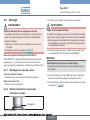
6.2 Function
The seat of the valve is always closed against the medium flow.
Spring force (CFA) or pneumatic pilot pressure (CFB and CFI) gen-
erates the closing force on the control cone. The force is transferred
via a spindle which is connected to the actuator piston.
6.2.1 Control functions (CF)
WARNING!
For control function I – Danger if pilot pressure fails!
For control function I control and resetting occur pneumatically. If
the pressure fails, no defined position is reached.
▶ To ensure a controlled restart, first pressurize the device with pilot
pressure, then switch on the medium.
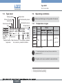
A
P
A
Normally closed by spring action.
english

7
Technical data
Type 2301
B
P
A
Normally open by spring action.
I
P
A
Actuating function via reciprocal pressurization.
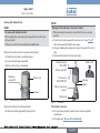
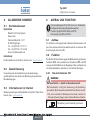
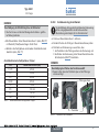
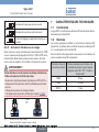
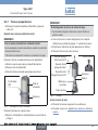
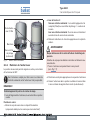
6.2.2 Flow direction below the seat
Depending on the version, the valve is closed against the medium
flow with spring force (control function A, CFA) or with pilot pressure
(control function B or I, CFB or CFI).
As the medium pressure is under the control cone, this pressure con-
tributes to the opening of the valve.
WARNING!
Medium may be discharged if minimum pilot pressure is too
low or medium pressure too high!
If the minimum pilot pressure is too low for CFB and CFI or the
permitted medium pressure is exceeded, leaks may occur.
▶ Observe minimum pilot pressure.
▶ Do not exceed medium pressure (see chapter “Pressure ranges”).
CFA CFB / CFI
Fig. 1: Flow direction below the seat
(Rest open/closed, closing against medium)
7 TECHNICAL DATA
7.1 Conformity
In accordance with the EC Declaration of conformity, Type 2301 ist
compliant with the EC Directives.
7.2 Standards
The applied standards, which verify conformity with the EC Directives,
can be found on the EC-Type Examination Certificate and / or the EC
Declaration of Conformity.
According to Pressure Equipment Directive the following operating
conditions must be observed:
Line connection
orifice
Maximum pressure for compressible fluids
of Group 1 (hazardous gases and vapors
according to Art. 3 No. 1.3 Letter a first
dash)
DN65 15 bar
DN80 12.5 bar
DN100 10 bar
english

8
Technical data
Type 2301
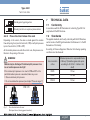
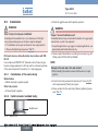
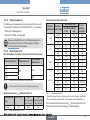
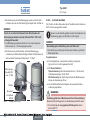
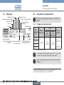
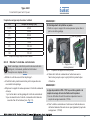
7.3 Type label
00189145
2301 A 25M PTFE VA
Tmed -10°C - +185°C
Flow 1 2
Pilot 5,5-7bar
Pmed 16,0bar
W3ZLT
G1" Kvs12,0
CE identification
Permitted pilot pressure
Permitted medium pressure
Type
Control function (CF)
Orifice of the seat /
actuator size
Sealing material
Body material
Identification
number
Flow direction
Permitted medium
temperature
Date of
manufacture
Main dimensions of
line connection
Flow capacity in standard
production conditions
7.4 Operating conditions
Observe permitted ranges on the type label of the device!
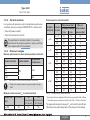
7.4.1 Temperature ranges
Actuator
size
[mm]
Actuator
material
Medium
Environment
1)
Seat seal
steel - steel
Seat seal
PTFE - steel
ø 50
PPS -10...+185 °C -10...+130 °C
0...+60 °C
2)
0...+100 °C
3)
ø 70
ø 90
ø 130
Tab. 1: Temperature ranges
1) If a pilot valve/control unit is used, the max. ambient tem-
perature is +55 °C.
The globe control valve is suitable for steam sterilization.
2) Pilot air ports with push-in connector
3) Pilot air ports with threaded bushing
english

9
Technical data
Type 2301
7.4.2 Control medium
In conjunction with pneumatic control units (positioner and process
controllers), pilot air according to DIN ISO 8573-1 must be used:
• Class 3 (for water content)
• Class 5 (for dust and oil content).
The specification is described in detail in the operating
instructions of the respective positioner / process controller
in the chapter entitled “Technical data”.
7.4.3 Pressure ranges
Maximum pilot pressure for valves without pneumatic control units
Actuator size (mm) Actuator material
Max. permitted
pilot pressure
4)
ø 50
PPS
10 barø 70
ø 90
ø 130 7 bar
Tab. 2: Pilot pressure for valves without pneumatic control units
4) Observe the maximum pressure range according to the type
label!
Minimum control pressure P
min
for control function A
Actuator size
[mm]
50 / 70 / 90 130
(Connection size
32 – 50 mm)
130
(Connection size
65 – 100 mm)
P
min
[bar] 5.5 5.5 5.6
Tab. 3: Minimum control pressure for CFA
Pilot pressure for control function B
Actuator
size [mm]
Connection
size [mm]
Pilot pressure [bar]
Max. per-
mitted medium
pressure [bar]
for medium pressure
0 bar max.
ø 50
4 – 15 5.1 7.0 16
20 5.1 7.0 9
25 5.1 7.0 5
ø 70
4 – 15 5.2 6.2 16
20 5.2 6.8 16
25 5.2 7.0 12
ø 90
25 2.4 4.2 16
32 2.5 5.3 16
40 2.5 6.5 16
50 2.5 7.0 14
ø 130
32 2.7 4.0 16
40 2.7 4.5 16
50 2.7 5.6 16
65 2.7 7.0 16 (15*)
80 2.7 7.0 10
100 2.7 7.0 6
Tab. 4: Pilot pressure for control function B
* According to Pressure Equipment Directive for compressible fluids of Group
1 (hazardous gases and vapors according to Art. 3 No. 1.3 Letter a first dash)
The required minimum pilot pressure P
min
with control function B and
I (flow below the seat) is dependent on the pressure of the medium.
english

10
Technical data
Type 2301
The pressure diagrams are in the operating instructions on
the Internet: www.burkert.com
7.5 General technical data
Media
Control medium neutral gases, air
Flow media Water, Alcohol, Fuel, Hydraulic liquids,
Saline solutions, Lyes, Organic solvents
Installation position as required, preferably with actuator in
upright position
Protection class IP67 in accordance with
IEC 529/EN 60529
Control functions (CF) The valve seat is always closed against the
medium flow
Control function A Normally closed by spring action
Control function B Normally open by spring action
Control function I Actuating function via reciprocal
pressurization
8 INSTALLATION
8.1 Safety instructions
DANGER!
Danger – high pressure in the equipment!
▶ Before loosening the lines and valves, turn off the pressure and
vent the lines.
WARNING!
Risk of injury from improper installation!
▶ Installation may be carried out by authorised technicians only and
with the appropriate tools!
Risk of injury from unintentional activation of the system and
an uncontrolled restart!
▶ Secure system from unintentional activation.
▶ Following assembly, ensure a controlled restart.
For control function I – Danger if pilot pressure fails!
For control function I control and resetting occur pneumatically.
If the pressure fails, no defined position is reached.
▶ To ensure a controlled restart, first pressurize the device with pilot
pressure, then switch on the medium.
Risk of injury from moving parts in the device!
▶ Do not reach into openings.
8.2 Before installation
• The globe control valve can be installed in any installation position,
preferably with the actuator in upright position.
• Before connecting the valve, ensure the pipelines are flush.
• Make certain the flow direction is correct (Flow direction always
below seat).
8.2.1 Preparatory work
→ Clean pipelines (Sealing material, swarf, etc.).
english

11
Technical data
Type 2301
Devices with welded body
NOTE!
For valves with installed control:
When welding the valve body into the pipeline, the control must
not be installed.
▶ Remove control from the actuator described below.
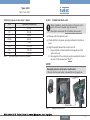
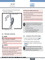
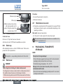
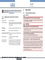
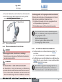
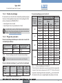
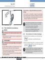
Remove the control unit from the actuator (if present):
→ Clamp the valve body in a holding device.
→ Loosen the fastening screws (2x).
→ Remove the control unit upwards.
Fastening
screw (2x)
Control unit
Actuator
Fig. 2: Disassembly the control unit
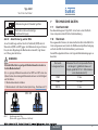
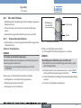
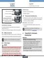
Remove the actuator from the valve body.
→ Install collet (white grommet) in pilot air port 1.
NOTE!
Damage to the seat seal or the seat contour!
▶ When removing the actuator, ensure that the valve is in open
position.
→ Control function A pressurize the pilot air port 1 (see “Fig. 3”)
with compressed air (5 bar): valve opens.
→ Using a suitable open-end wrench, place the wrench flat on the
pipe.
→ Unscrew the actuator from the valve body.
Actuator
Nipple
Valve body
Flats for open-end
wrench
Pilot air port
CFA, CFB, CFI
Exhaust air port
CFA, CFB
Pilot air port CFI
2
1
Install collet:
Fig. 3: Installation
Other device versions
→ Do not remove actuator unless this is a customer-specific
requirement.
→ Procedure see “Devices with welded body”.
english

12
Technical data
Type 2301
8.3 Installation
WARNING!
Risk of injury from improper installation!
Assembly with unsuitable tools or non-observance of the tight-
ening torque is dangerous as the device may be damaged.
▶ For installation use an open-end wrench, never a pipe wrench.
▶ Observe the tightening torque (see “Tab. 5”).
Dirt trap for devices with authorisation in accordance with DIN
EN 161
In accordance with DIN EN 161 “Automatic shut-off valves for gas
burners and gas appliances” a dirt trap must be connected upstream
of the valve and prevent the insertion of a 1 mm plug gauge.
8.3.1 Installation of the valve body
Welded bodies
→ Weld valve body in pipeline system.
Other body versions
→ Connect body to pipeline.
8.3.2 Install actuator (welded body)
Graphite seal
Fig. 4: Graphite seal
→ Check the graphite seal and if required, replace it.
WARNING!
Danger if incorrect lubricants used!
Unsuitable lubricant may contaminate the medium. In oxygen appli-
cations there is a risk of an explosion!
▶ In specific applications, e.g. oxygen or analysis applications, use
appropriately authorized lubricants only.
→ Grease nipple thread before re-installing the actuator (e.g. with
Klüber paste UH1 96-402 from Klüber).
NOTE!
Damage to the seat seal or the seat contour!
▶ When installing the actuator, ensure that the valve is in open
position.
→ Control function A pressurize the pilot air port 1 (see „Fig. 5“)
with compressed air (5 bar): valve opens.
→ Screw actuator into the valve body. Observe tightening torque
(see “Tab. 5”).
english

13
Technical data
Type 2301
Tightening torques of valve body / nipples
DN Tightening torque [Nm]
10/15 45 ±3
20 50 ±3
25 60 ±3
32/40 65 ±3
50 70 ±3
65 100 ±3
80 120 ±5
100 150 ±5
Tab. 5: Tightening torques of valve body / nipples
8.3.3 Install control unit
Before installation, check the position of the ports on the
control unit and, if required, align the actuator.
Description see chapter “8.3.4 Rotating the actuator”.
→ Remove collet from pilot air port 1.
→ Check that the O-rings are correctly positioned in the pilot air
ports.
→ Align the puck holder and the control unit until
1. the puck holder can be inserted into the guide rail of the
control unit and
2. the supports of the control unit can be inserted into the pilot
air ports of the actuator (see “Fig. 5”).
NOTE!
Damaged printed circuit board or malfunction!
▶ Ensure that the puck holder is situated flat on the guide rail.
Guide rail
Puck holder
Fig. 5: Aligning the puck holder
english

14
Technical data
Type 2301
→ Push the control unit, without turning it, onto the actuator until no
gap is visible on the form seal.
NOTE!
Too high torque when screwing in the fastening screw does
not ensure protection class IP65 / IP67!
▶ The fastening screws may be tightened to a maximum torque of
1.5 Nm only.
→ Attach the control unit to the actuator using the two side fastening
screws. In doing so, tighten the screws only hand-tight (max.
torque: 1.5 Nm).
Supports
Pilot air ports
actuator
Fastening
screws
max. 1.5 Nm
Fig. 6: Install control unit
8.3.4 Rotating the actuator
The position of the connections can be aligned steplessly by rotating
the actuator through 360°.
Only the entire actuator can be rotated. The control unit cannot
be rotated contrary to the actuator.
NOTE!
Damage to the seat seal or the seat contour!
▶ When rotating the actuator, ensure that the valve is in open
position.
Procedure:
→ Clamp the valve body in a holding device (applies only to valves
which have not yet been installed).
→ Control function A:
Without unit control: pressurize the pilot air port 1 with com-
pressed air (5 bar): valve opens.
With unit control: open the valve according to the operating
instructions for the control unit.
→ Counter on the flats of the nipple with a suitable open-end
wrench.
WARNING!
Risk of injury from discharge of medium and pressure!
If the direction of rotation is wrong, the body interface may become
detached.
▶ Rotate the actuator module in the specified direction only
(see “Fig. 7”)!
→ Place suitable open-end wrench on the hexagon of the actuator.
english

15
Technical data
Type 2301
→ Rotate counter-clockwise (as seen from below) to bring the
actuator into the required position.
Open-end wrench
Fig. 7: Rotating with open-end wrench
8.4 Pneumatic connection
DANGER!
Danger – high pressure in the equipment!
▶ Before loosening the lines and valves, turn off the pressure and
vent the lines.
WARNING!
For control function I – Danger if pilot pressure fails!
For control function I control and resetting occur pneumatically.
If the pressure fails, no defined position is reached.
▶ To ensure a controlled restart, first pressurize the device with pilot
pressure, then switch on the medium.
Risk of injury from unsuitable connection hoses!
Hoses which cannot withstand the pressure and temperature range
may result in hazardous situations.
▶ Use only hoses which are authorized for the indicated pressure
and temperature range.
▶ Observe the data sheet specifications from the hose manufacturers.
The pneumatic connection of the globe control valve can
be carried out only in connection with the appropriate
control unit.
Possible control units are:
Positioner Type 8692, 8694, 8696 and 8792
Process controller Type 8693 and 8793
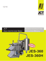
8.4.1 Connection of the control medium
→ Connect the control medium to the pilot air port (“Fig. 8”: 1)
(3 – 7 bar; instrument air, free of oil, water and dust).
→ Fit the exhaust line or a silencer to the exhaust air port
(“Fig. 8”: 3) and, if available, to the additional exhaust air port
(“Fig. 8”: 3.1).
If used in an aggressive environment, we recommend
conveying all free pneumatic connections into a neutral
atmosphere with the aid of a pneumatic hose.
english

16
Technical data
Type 2301
Pilot air port
Exhaust air port
Additional exhaust air port only
with pilot-operated control
system for high air output from
(actuator size ø 130)
1
3
3.1
Fig. 8: Pneumatic connection
Control air hose:
6/4 mm or 1/4” pilot air hoses can be used.
A pilot air port via G 1/8” thread is available as an option.
8.5 Start-up
After installing the device, run the X.TUNE function. This function
presets the control parameters.
Description – see operating instructions for the control.
8.6 Removal
DANGER!
Risk of injury from discharge of medium and pressure!
It is dangerous to remove a device which is under pressure due to
the sudden release of pressure or discharge of medium.
▶ Before removing a device, switch off the pressure and vent the lines.
Procedure:
→ Loosen the pneumatic connection.
→ Remove the device.
8.7 Maintenance work
→ Complete a visual inspection of the equipment once a year. Shorter
maintenance intervals may be recommended depending on the
operating conditions.
Wear parts: seals and swivel plate.
→ In the event of a leak, replace the relevant wear part.
The maintenance and repair instructions are available on the
Internet: www.burkert.com
9 PACKAGING, TRANSPORT,
STORAGE
NOTE!
Transport and storage damage!
• Protect the device against moisture and dirt in shock-resistant
packaging during transportation and storage.
• Permitted storage temperature: -20...+65 °C.
Damage to the environment caused by device components
contaminated with media.
• Ensure the device and packaging are disposed of in an environ-
mentally sound manner!
english

17
Der Quickstart
1 DER QUICKSTART ....................................................................................17
2 DARSTELLUNGSMITTEL .......................................................................18
3 BESTIMMUNGSGEMÄSSE VERWENDUNG................................18
4 GRUNDLEGENDE SICHERHEITSHINWEISE ..............................19
5 ALLGEMEINE HINWEISE .......................................................................20
6 AUFBAU UND FUNKTION .................................................................... 20
7 TECHNISCHE DATEN .............................................................................21
8 MONTAGE .....................................................................................................24
9 TRANSPORT LAGERUNG, ENTSORGUNG .................................30
Typ 2301
1 DER QUICKSTART
Der Quickstart beschreibt den gesamten Lebenszyklus des Geräts.
Bewahren Sie diese Anleitung so auf, dass sie für jeden Benutzer gut
zugänglich ist und jedem neuen Eigentümer des Geräts wieder zur
Verfügung steht.
Wichtige Informationen zur Sicherheit!
Lesen Sie den Quickstart sorgfältig durch. Beachten Sie vor allem
die Kapitel „Grundlegende Sicherheitshinweise“ und „Bestim-
mungsgemäße Verwendung“.
▶ Der Quickstart muss gelesen und verstanden werden.
Der Quickstart erläutert beispielhaft die Montage und Inbetriebnahme
des Geräts.
Die ausführliche Beschreibung des Geräts finden Sie in der
Bedienungsanleitung für den Typ 2301.
Die Bedienungsanleitung finden Sie im Internet unter:
www.buerkert.de
1.1 Begriffsdefinition / Abkürzung
Der in dieser Anleitung verwendete Begriff „Gerät“ steht immer für
das Geradsitzregelventil Typ 2301.
Die in dieser Anleitung verwendete Abkürzung „Ex“ steht immer
für „explosionsgeschützt“.
deutsch

18
Darstellungsmittel
Typ 2301
2 DARSTELLUNGSMITTEL
GEFAHR!
Warnt vor einer unmittelbaren Gefahr.
▶ Bei Nichtbeachtung sind Tod oder schwere Verletzungen die Folge.
WARNUNG!
Warnt vor einer möglicherweise gefährlichen Situation.
▶ Bei Nichtbeachtung können schwere Verletzungen oder Tod die
Folge sein.
VORSICHT!
Warnt vor einer möglichen Gefährdung.
▶ Nichtbeachtung kann mittelschwere oder leichte Verletzungen
zur Folge haben.
HINWEIS!
Warnt vor Sachschäden.
Wichtige Tipps und Empfehlungen.
Verweist auf Informationen in dieser Bedienungsanleitung
oder in anderen Dokumentationen.
▶ markiert eine Anweisung zur Gefahrenvermeidung.
→ markiert einen Arbeitsschritt, den Sie ausführen müssen.
3 BESTIMMUNGSGEMÄSSE
VERWENDUNG
Bei nicht bestimmungsgemäßem Einsatz des Geradsitzregel-
ventils Typ 2301 können Gefahren für Personen, Anlagen in
der Umgebung und die Umwelt entstehen.
▶ Das Gerät ist für die Steuerung des Durchflusses von flüssigen
und gasförmigen Medien konzipiert. Es kann nur in Kombination
mit einer entsprechenden Ansteuerung betrieben werden.
▶ Im explosionsgefährdeten Bereich darf das Geradsitzregelventil
Typ 2301 nur entsprechend der Spezifikation auf dem separaten
Ex-Typschild eingesetzt werden. Für den Einsatz muss die dem
Gerät beiliegende Zusatzinformation mit Sicherheitshinweisen für
den Ex-Bereich beachtet werden.
▶ Geräte ohne separates Ex-Typschild dürfen nicht im explosions-
gefährdeten Bereich eingesetzt werden.
▶ Für den Einsatz die in den Vertragsdokumenten, der Bedienungs-
anleitung und auf dem Typschild spezifizierten zulässigen Daten,
Betriebs- und Einsatzbedingungen beachten. Diese sind im Kapitel
„Technische Daten“ beschrieben.
▶ Das Gerät nur in Verbindung mit von Bürkert empfohlenen bzw.
zugelassenen Fremdgeräten und -komponenten einsetzen.
▶ Voraussetzungen für den sicheren und einwandfreien Betrieb
sind sachgemäßer Transport, sachgemäße Lagerung und Instal-
lation sowie sorgfältige Bedienung und Instandhaltung.
▶ Das Gerät nur bestimmungsgemäß einsetzen.
3.1 Beschränkungen
Beachten Sie bei der Ausfuhr des Systems oder Geräts gegebenenfalls
bestehende Beschränkungen.
deutsch

19
Grundlegende Sicherheitshinweise
Typ 2301
4 GRUNDLEGENDE
SICHERHEITSHINWEISE
Diese Sicherheitshinweise berücksichtigen keine
• Zufälligkeiten und Ereignisse, die bei Montage, Betrieb und Wartung
der Geräte auftreten können.
• ortsbezogenen Sicherheitsbestimmungen, für deren Einhaltung, auch
in Bezug auf das Montagepersonal, der Betreiber verantwortlich ist.
Verletzungsgefahr durch hohen Druck in Anlage oder Gerät.
▶ Vor Arbeiten an Anlage oder Gerät den Druck abschalten und
Leitungen entlüften und entleeren.
Verletzungsgefahr durch Stromschlag.
▶ Vor Arbeiten an Anlage oder Gerät die Spannung abschalten
und vor Wiedereinschalten sichern.
▶ Die geltenden Unfallverhütungs- und Sicherheitsbestimmungen
für elektrische Geräte beachten!
Verbrennungsgefahr.
Bei Dauerbetrieb kann die Geräteoberfläche heiß werden.
▶ Das Gerät nicht mit bloßen Händen berühren.
Verletzungsgefahr durch sich bewegende Teile im Gerät.
▶ Nicht in Öffnungen fassen.
Verletzungsgefahr durch herausspringende Feder beim Öffnen
des Antriebs.
▶ Der Antrieb darf nicht geöffnet werden.
Allgemeine Gefahrensituationen.
Zum Schutz vor Verletzungen beachten:
▶ Anlage oder Gerät vor unbeabsichtigtem Betätigen sichern.
▶ Nur geschultes Fachpersonal darf Installations- und Instandhal-
tungsarbeiten ausführen.
▶ Nach einer Unterbrechung der elektrischen oder pneumatischen
Versorgung ist ein definierter oder kontrollierter Wiederanlauf
des Prozesses zu gewährleisten.
▶ Gerät nur in einwandfreiem Zustand und unter Beachtung der
Bedienungsanleitung betreiben.
▶ Für die Einsatzplanung und den Betrieb des Geräts die allgemeinen
Regeln der Technik einhalten.
Zum Schutz vor Sachschäden am Gerät ist zu beachten:
• In Medienanschlüsse nur Medien einspeisen, die im Kapitel „Tech-
nische Daten“ aufgeführt sind.
• Gerät nicht mechanisch belasten (z. B. durch Ablage von Gegen-
ständen oder als Trittstufe).
• Keine äußerlichen Veränderungen an den Ventilen vornehmen.
Gehäuseteile und Schrauben nicht lackieren.
deutsch

20
Allgemeine Hinweise
Typ 2301
5 ALLGEMEINE HINWEISE
5.1 Kontaktadressen
Deutschland
Bürkert Fluid Control Systems
Sales Center
Christian-Bürkert-Str. 13-17
D-74653 Ingelfingen
Tel. + 49 (0) 7940 - 10 91 111
Fax + 49 (0) 7940 - 10 91 448
E-mail: [email protected]
International
Die Kontaktadressen finden Sie im Internet unter: www.burkert.com
5.2 Gewährleistung
Voraussetzung für die Gewährleistung ist der bestimmungs-
gemäße Gebrauch des Geräts unter Beachtung der spezifizierten
Einsatzbedingungen.
5.3 Informationen im Internet
Bedienungsanleitungen und Datenblätter zum Typ 2301 finden Sie im
Internet unter: www.buerkert.de
6 AUFBAU UND FUNKTION
Das Geradsitzregelventil Typ 2301 kann nur in Kombination
mit folgenden Ansteuerungen betrieben werden:
Positioner Typ 8692, 8694, 8696 und 8792
Prozessregler Typ 8693 und 8793
6.1 Aufbau
Die Ventilsitze sind eingeschraubt. Reduzierte Sitznennweiten sind
durch den Austausch der Einschraubsitze einfach zu realisieren. Die
Anströmung ist immer unter Sitz.
6.2 Funktion
Der Sitz des Ventils wird immer gegen den Mediumsstrom geschlossen.
Federkraft (SFA) oder pneumatischer Steuerdruck (SFB und SFI)
erzeugen die Schließkraft auf den Regelkegel. Über eine Spindel, die
mit dem Antriebskolben verbunden ist, wird die Kraft übertragen.
6.2.1 Steuerfunktionen (SF)
WARNUNG!
Bei Steuerfunktion I – Gefahr bei Steuerdruckausfall!
Bei Steuerfunktion I erfolgt die Ansteuerung und Rückstellung
pneumatisch. Bei Druckausfall wird keine definierte Position erreicht.
▶ Für einen kontrollierten Wiederanlauf das Gerät zunächst mit
Steuerdruck beaufschlagen, danach erst das Medium aufschalten.
A
P
A
In Ruhestellung durch Federkraft geschlossen.
deutsch
Seite wird geladen ...
Seite wird geladen ...
Seite wird geladen ...
Seite wird geladen ...
Seite wird geladen ...
Seite wird geladen ...
Seite wird geladen ...
Seite wird geladen ...
Seite wird geladen ...
Seite wird geladen ...
Seite wird geladen ...
Seite wird geladen ...
Seite wird geladen ...
Seite wird geladen ...
Seite wird geladen ...
Seite wird geladen ...
Seite wird geladen ...
Seite wird geladen ...
Seite wird geladen ...
Seite wird geladen ...
Seite wird geladen ...
Seite wird geladen ...
Seite wird geladen ...
Seite wird geladen ...
Seite wird geladen ...
Seite wird geladen ...
-
 1
1
-
 2
2
-
 3
3
-
 4
4
-
 5
5
-
 6
6
-
 7
7
-
 8
8
-
 9
9
-
 10
10
-
 11
11
-
 12
12
-
 13
13
-
 14
14
-
 15
15
-
 16
16
-
 17
17
-
 18
18
-
 19
19
-
 20
20
-
 21
21
-
 22
22
-
 23
23
-
 24
24
-
 25
25
-
 26
26
-
 27
27
-
 28
28
-
 29
29
-
 30
30
-
 31
31
-
 32
32
-
 33
33
-
 34
34
-
 35
35
-
 36
36
-
 37
37
-
 38
38
-
 39
39
-
 40
40
-
 41
41
-
 42
42
-
 43
43
-
 44
44
-
 45
45
-
 46
46


Burkert 2300 Series Schnellstartanleitung
- Typ
- Schnellstartanleitung
- Dieses Handbuch eignet sich auch für
in anderen Sprachen
Verwandte Artikel
Andere Dokumente
-
GEM 553 Installation, Operating And Maintenance Instruction
-
-
-
GEM 550 Bedienungsanleitung
-
 MA lighting MA Switch Quick Manual
-
-
Gemu 565 Bedienungsanleitung
-
GF Butterfly valve Type 567 DN350 - DN600 Benutzerhandbuch
-
 Jct JES-360 Bedienungsanleitung
-
Festo VABF-S7-F1B1P2-F Assembly Instructions

