Pepperl+Fuchs ENI58PL-R*** Bedienungsanleitung
- Typ
- Bedienungsanleitung

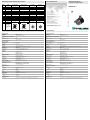
Elektrischer Anschluss/Electrical Connection
Adressen/Addresses
www.pepperl-fuchs.com
Pepperl+Fuchs GmbH
68301 Mannheim · Germany
Te l . +49 621 776-4411
Fax +49 621 776-27-4411
E-mail: fa-info@de.pepperl-fuchs.com
Worldwide Headquarters
Pepperl+Fuchs GmbH · Mannheim · Germany
E-mail: fa-[email protected]
USA Headquarters
Pepperl+Fuchs Inc. · Tw i nsburg · USA
E-mail: fa-info@us.pepperl-fuchs.com
Asia Pacific Headquarters
Pepperl+Fuchs Pte Ltd · Singapore
E-mail: [email protected]
Company Registration No. 199003130E
Technical Data
Technische Daten
Allgemeine Daten
Erfassungsart magnetische Abtastung
Linearitätsfehler ± 0,1 °
Impulszahl programmierbar von 1 ... 16384
Kenndaten funktionale Sicherheit
MTTFd 140 a
Gebrauchsdauer (TM) 20 a
L10 70 E+9 bei 6000 min-1
Diagnosedeckungsgrad (DC) 0 %
Elektrische Daten
Betriebsspannung UB4,75 ... 30 V DC
Leerlaufstrom I0max. 50 mA
Ausgang
Ausgangstyp HTL/TTL programmierbar
Laststrom pro Kanal max. 50 mA , kurzschlussfest, verpolsicher
Ausgangsfrequenz max. 1000 kHz
Anstiegszeit 300 ns
Phasenlage A zu B 90 ° ± 14 ° bei Geschwindigkeit > 100 min-1
Tastverhältnis 1/2 ± 15 % bei Geschwindigkeit > 100 min-1
Anschluss
Gerätestecker M12-Stecker, 8-polig
M12-Stecker, 5-polig
M23-Stecker, 12-polig
Kabel Ø6 mm, 4 x 2 x 0,14 mm2
Normenkonformität
Schutzart DIN EN 60529, IP65, IP67
Klimaprüfung DIN EN 60068-2-78 , keine Betauung
Störaussendung EN 61000-6-4:2007/A1:2011
Störfestigkeit EN 61000-6-2:2005
Schockfestigkeit DIN EN 60068-2-27, 100 g, 6 ms
Schwingungsfestigkeit DIN EN 60068-2-6, 10 g, 10 ... 1000 Hz
Umgebungsbedingungen
Arbeitstemperatur Kabel, beweglich: -5 ... 70 °C (23 ... 158 °F)
Kabel, fest verlegt: -30 ... 70 °C (-22 ... 158 °F)
bei Steckerabgang: -40 ... 85 °C (-40 ... 185 °F)
Lagertemperatur -40 ... 85 °C (-40 ... 185 °F)
Mechanische Daten
Material
Gehäuse Stahl, vernickelt , lackiert
Flansch Aluminium
Welle Edelstahl
Masse ca 300 g
Drehzahl max. 3000 min -1
Trägheitsmoment ≤ 30 gcm2
Anlaufdrehmoment ≤ 3 Ncm bei IP65 , ≤ 5 Ncm bei IP67
Wellenbelastung
Axial max. 40 N
Radial max. 110 N
Werkseinstellungen
Voreinstellung Ausgangstyp HTL , Impulszahl 1024 , Drehrichtung A vor B (im Uhrzeigersinn)
General specifications
Detection type magnetic sampling
Linearity error ± 0.1 °
Pulse count configurable from 1 ... 16384
Functional safety related parameters
MTTFd 140 a
Mission Time (TM) 20 a
L10 70 E+9 at 6000 rpm
Diagnostic Coverage (DC) 0 %
Electrical specifications
Operating voltage UB4.75 ... 30 V DC
No-load supply current I0max. 50 mA
Output
Output type HTL/TTL configurable
Load current max. per channel 50 mA , short-circuit protected, reverse polarity protected
Output frequency max. 1000 kHz
Rise time 300 ns
Phase position A to B 90 ° ± 14 ° for speed > 100 min-1
Duty cycle 1/2 ± 15 % for speed > 100 min-1
Connection
Connector M12 connector, 8-pin
M12 connector, 5 pin
M23 connector, 12-pin
Cable Ø6 mm, 4 x 2 x 0.14 mm2
Standard conformity
Degree of protection DIN EN 60529, IP65, IP67
Climatic testing DIN EN 60068-2-78 , no moisture condensation
Emitted interference EN 61000-6-4:2007/A1:2011
Noise immunity EN 61000-6-2:2005
Shock resistance DIN EN 60068-2-27, 100 g, 6 ms
Vibration resistance DIN EN 60068-2-6, 10 g, 10 ... 1000 Hz
Ambient conditions
Operating temperature cable, flexing: -5 ... 70 °C (23 ... 158 °F)
cable, fixed: -30 ... 70 °C (-22 ... 158 °F)
connector models: -40 ... 85 °C (-40 ... 185 °F)
Storage temperature -40 ... 85 °C (-40 ... 185 °F)
Mechanical specifications
Material
Housing nickel-plated steel , painted
Flange Aluminum
Shaft Stainless steel
Mass ca 300 g
Rotational speed max. 3000 min -1
Moment of inertia ≤ 30 gcm2
Starting torque ≤ 3 Ncm for IP65 , ≤ 5 Ncm for IP67
Shaft load
Axial max. 40 N
Radial max. 110 N
Factory settings
Default setting output type HTL , pulse count 1024 , direction of rotation A before B (clockwise)
Inkremental-Drehgeber
Incremental rotary encoder
ENI58PL-R***
Part. No.:
Date:
T187373
2019-03 DIN A3 -> DIN
45-5472B
Doc. No.:
Signal
Cable Connector M23,
12-pin, clockwise
Connector M23,
12-pin, counterclockwise
Connector
M12 x 1,8-pin
Connector
M12 x 1, 5-pin
GND White 10 10 1 3
UbBrown 12 12 2 1
A Green 5 5 3 2
B Gray 8 8 5 4
A Yellow 6 6 4 -
B Pink 1 1 6 -
Z Blue 3 3 7 5
Z Red 4 4 8 -
NC - 2 2 - -
NC - 7 7 - -
NC - 9 9 - -
NC - 11 11 - -
Screen Housing Housing Housing Housing Housing
Note:
Unused cores
must be insula-
ted individually
before commi-
sioning in order
to avoid interfe-
rence..
1 2 11
9 8 10 7
3
12 6
45
8 7 11
9 1 12 2
6
10 3
54
1
4
6
7
8
53
2
1
3
4
5
2

Entstörmaßnahmen
Der Einsatz hochentwickelter Mikroelektronik erfordert ein konsequent ausgeführtes Entstör- und Verdrahtungskonzept. Dies umso mehr, je
kompakter die Bauweise und je höher die Leistungsanforderungen in modernen Maschinen werden. Die folgenden Installationshinweise und -
vorschläge gelten für „normale Industrieumgebungen“. Eine für jede Störumgebung optimale Lösung gibt es nicht.
Beim Anwenden der folgenden Maßnahmen sollte der Geber eine einwandfreie Funktion zeigen:
• Bei Ausführung RS422 ist das Leitungsende bei langen Leitungen mit einem geeigneten Wellenwiderstand abzuschließen.
• Als Anschlussleitung sind durchgehend geschirmte Leitungen zu verwenden. Für Anschluss der Ausführung RS422 ist zusätzlich ein
Paarverseilung der Einzeladern erforderlich.
• Die Verdrahtung des Drehgebers ist in großem Abstand von mit Störungen belasteten Energieleitungen zu legen.
• Kabelquerschnitt des Schirms mindestens 4 mm².
• Kabelquerschnitt mindestens 0,14 mm².
• Die Verdrahtung von Schirm und 0 V ist möglichst sternförmig zu halten.
• Kabel nicht knicken oder klemmen.
• Minimalen Krümmungsradius von 10 mm einhalten und Zug- sowie Scherbeanspruchung vermeiden.
Betriebshinweise
Jeder Pepperl+Fuchs-Drehgeber verlässt das Werk in einem einwandfreien Zustand. Um diese Qualität zu erhalten und einen störungsfreien Betrieb
zu gewährleisten, sind die folgenden Spezifikationen zu berücksichtigen:
• Schockeinwirkungen auf das Gehäuse und vor allem auf die Geberwelle sowie axiale und radiale Überbelastung der Geberwelle sind zu
vermeiden.
• Die Genauigkeit und Lebensdauer des Gebers wird nur bei Verwendung einer geeigneten Kupplung bzw. Drehmomentstütze garantiert.
• Die Verdrahtungsarbeiten sind nur im spannungslosen Zustand durchzuführen.
• Die maximalen Betriebsspannungen und der maximal zulässige Ausgangstrom dürfen nicht überschritten werden. Die Geräte sind mit
Sicherheitskleinspannungen zu betreiben.
• Sensorleitungen sind intern mit der Spannungsversorgung verbunden und können bei langer Kabelzuleitung für die Spannungseinstellung oder
–regelung am Geber verwendet werden.
• Nicht benutzte Sensorleitungen sind entweder zu isolieren oder GND Sens mit GND und Ub Sens mit UB zu verbinden.
• Unbenutzte Ausgänge sind vor der Unbetriebnahme zu isolieren
Hinweise zum Auflegen des Schirms
Die Störsicherheit an einer Anlage wird entscheidend von der richtigen Schirmung bestimmt. Gerade in diesem Bereich treten häufig Installationsfehler
auf. Oft wird der Schirm nur einseitig aufgelegt und dann mit einem Draht an die Erdungsklemme angelötet, was im Bereich der NF-Technik seine
Berechtigung hat. Bei EMV geben jedoch die Regeln der HF-Technik den Ausschlag. Ein Grundziel der HF-Technik ist, dass HF-Energie über eine
möglichst niedrige Impedanz auf Erde geführt wird, da sie sich ansonsten in das Kabel entlädt. Eine niedrige Impedanz erreicht man durch eine
großflächige Verbindung mit Metallflächen.
Folgende Hinweise sind zu beachten:
• Der Schirm ist beidseitig großflächig auf „gemeinsame Erde“ aufzulegen, sofern nicht die Gefahr von Potenzialausgleichsströmen besteht.
• Der Schirm ist in seinem ganzen Umfang hinter die Isolierung zurückzuziehen und dann großflächig unter eine Zugentlastung zu klemmen.
• Die Zugentlastung ist bei Kabelanschluss an die Schraubklemmen direkt und großflächig mit einer geerdeten Fläche zu verbinden.
• Bei der Verwendung von Steckern sind nur metallisierte Stecker zu verwenden (z. B. Sub-D-Stecker mit metallisiertem Gehäuse). Auf die direkte
Verbindung der Zugentlastung mit dem Gehäuse ist zu achten.
Hinweis
Die Programmierung erfolgt über einen geeigneten IO-Link-Master.
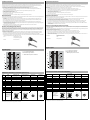
Installationshinweise
Signalausgänge
Elektrischer Anschluss für IO-Link-Programmierung
Signal Kabel Gerätestecker M23,
12-polig, rechtsdrehend
Gerätestecker M23, 12-
polig, linksdrehend
Gerätestecker
M12 x 1, 8-polig
Gerätestecker
M12 x 1, 5-polig
L- weiß 10 10 1 3
L+ braun 12 12 2 1
NC grün 5 5 3 2
NC grau 8 8 5 4
NC gelb 6 6 4 -
NC rosa 1 1 6 -
IO-Link blau 3 3 7 5
NC rot 4 4 8 -
NC - 2 2 - -
NC - 7 7 - -
NC - 9 9 - -
NC - 11 11 - -
Hinweis:
Nicht verwendete
Adern (NC) sind für
die Programmierung
einzeln zu isolieren,
um Störungen zu
vermeiden.
Vorteil: metallisierter Stecker, Schirm
unter Zugentlastung geklemmt
Nachteil: Anlöten des Schirms
B
A
B
Z
A
Z
90°
360°
*
cw - mit Blick auf die Welle
Phasenbeziehungen elektrisch
*
1 Messschritt entspricht 90° elektrisch
1 2 11
9 8 10 7
3
12 6
45
8 7 11
9 1 12 2
6
10 3
54
1
4
6
7
8
53
2
1
3
4
5
2
Anti-interference measures
The use of highly sophisticated microelectronics requires a consistently implemented anti-interference and wiring concept. This becomes all the more
important the more compact the constructions are and the higher the demands are on the performance of modern machines.
The following installation instructions and proposals apply for "normal industrial environments". There is no ideal solution for all interfering
environments.
When the following measures are applied, the encoder should be in perfect working order:
• With RS 422 Interface devices and long cables, a line-termination by a suitable termination resistor is required.
• A shielded cable should be used at installation. For the connection of RS 422 devices the wires must be twisted in pairs.
• The wiring of the encoder should be laid at a large distance to energy lines which could cause interferences.
• Cable cross-section of the screen at least 4 mm².
• Cable cross-section at least 0,14 mm².
• The wiring of the screen and 0 V should be arranged radially, if and when possible.
• Do not kink or jam the cables.
• Adhere to the minimum bending radius of 10 mm and avoid tensile as well as shearing load.
Operating instructions
Every encoder manufactured by Pepperl+Fuchs leaves the factory in a perfect condition. In order to ensure this quality as well as a faultless operation,
the following specifications have to be taken into consideration:
• Avoid any impact on the housing and in particular on the encoder shaft as well as the axial and radial overload of the encoder shaft.
• The accuracy and service life of the encoder is guaranteed only, if a suitable coupling and / or torque support is used.
• Any wiring work has to be carried out with the system in a dead condition.
• The maximum operating voltages and output currents must not be exceeded. The devices have to be operated at extra-low safety voltage.
• Sensor wires are connected internally to the supply voltage and may be used for Voltage adjustment or -control in case of long cables.
• Unused sensor wires should either isolated or connected to the corresponding supply potentials (GND Sens connected to GND and Ub Sens
connected to UB).
• Unused outputs must be isolatd before initial use of the encoder.
Notes on connecting the electric screening
The immunity to interference of a plant depends on the correct screening. In this field installation faults occur frequently. Often the screen is applied to
one side only, and is then soldered to the earthing terminal with a wire, which is a valid procedure in LF engineering. However, in case of EMC the rules
of HF engineering apply.
One basic goal in HF engineering is to pass the HF energy to earth at an impedance as low as possible as otherwise energy would discharge into the
cable. A low impedance is achieved by a large-surface connection to metal surfaces.
The following instructions have to be observed:
• Apply the screen on both sides to a "common earth" in a large surface, if there is no risk of equipotential currents.
• The screen has to be passed behind the insulation and has to be clamped on a large surface below the tension relief.
• In case of cable connections to screw-type terminals, the tension relief has to be connected to an earthed surface.
• If plugs are used, metallised plugs only should be fitted (such as sub D plugs with metallised housing). Please observe the direct connection of
the tension relief to the housing.
Note
The configuration is carried out via a suitable IO-Link Master.
Installation instructions
Signal outputs
Electrical connection for IO-Link configuration
Signal Cable Connector M23,
12-pin, clockwise
Connector M23,
12-pin,
counterclockwise
Connector
M12 x 1, 8-pin
Connector
M12 x 1, 5-pin
L- White 10 10 1 3
L+ Brown 12 12 2 1
NC Green 5 5 3 2
NC Grey 8 8 5 4
NC Yellow 6 6 4 -
NC Pink 1 1 6 -
IO-Link Blue 3 3 7 5
NC Red 4 4 8 -
NC - 2 2 - -
NC - 7 7 - -
NC - 9 9 - -
NC - 11 11 - -
Note:
Unused cores (NC)
must be insulated
individually for
programming in order
to avoid interference.
Advantage: metalised connector, shield
clamped with the strain relief
clamp
Disadvantage: soldering shield on
B
A
B
Z
A
Z
90°
360°
*
cw - with view onto the shaft
phase relationsships electrical
* 1 Measuring step is 90° electrical
1 2 11
9 8 10 7
3
12 6
45
8 7 11
9 1 12 2
6
10 3
54
1
4
6
7
8
53
2
1
3
4
5
2
-
 1
1
-
 2
2


Pepperl+Fuchs ENI58PL-R*** Bedienungsanleitung
- Typ
- Bedienungsanleitung
in anderen Sprachen
Verwandte Artikel
-
Pepperl+Fuchs ENA58IL-R***-SSI Bedienungsanleitung
-
-
-
-
-
-
-
-
-