Pepperl+Fuchs ESS58-PZ Bedienungsanleitung
- Typ
- Bedienungsanleitung

Elektrischer Anschluss/Electrical Connection
Technische Daten Technical Data
Adressen/Addresses
www.pepperl-fuchs.com
Pepperl+Fuchs GmbH
68301 Mannheim · Germany
Tel. +49 621 776-4411
Fax +49 621 776-27-4411
E-mail: fa-info@de.pepperl-fuchs.com
Worldwide Headquarters
Pepperl+Fuchs GmbH · Mannheim · Germany
E-mail: fa-info@de.pepperl-fuchs.com
USA Headquarters
Pepperl+Fuchs Inc. · Twinsburg · USA
E-mail: fa-info@us.pepperl-fuchs.com
Asia Pacific Headquarters
Pepperl+Fuchs Pte Ltd · Singapore
E-mail: [email protected]
Company Registration No. 199003130E
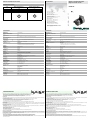
ESS58-PZ
Electrical connection
Pin Male connector M12 x 1,
4-pin, A-coded
Female connector M12 x 1,
4-pin, D-coded
1 + 24 V Tx +
2- Rx +
30 V Tx -
4- Rx -
1
3
4
2
1
3
42
Allgemeine Daten
Erfassungsart optische Abtastung
Kenndaten funktionale Sicherheit
MTTFd 130 a
Gebrauchsdauer (TM) 20 a
L10h 1,9 E+11 bei 6000 min-1 und 20/40 N axialer/radialer Wellenbelastung
Diagnosedeckungsgrad (DC) 0 %
Elektrische Daten
Betriebsspannung UB10 ... 30 V DC , sichere galvanische Trennung nach EN 50178
Leistungsaufnahme P0max. 3 W
Linearität ± 0,5 LSB (12 Bit) , ± 2 LSB (16 Bit)
Ausgabe-Code Binär-Code
Codeverlauf (Zählrichtung) parametrierbar,
cw steigend (bei Drehung im Uhrzeigersinn Codeverlauf steigend)
cw fallend (bei Drehung im Uhrzeigersinn Codeverlauf fallend)
Schnittstelle
Schnittstellentyp Ethernet Powerlink
Auflösung
Singleturn bis 16 Bit
Gesamtauflösung bis 16 Bit
Physikalisch Ethernet
Übertragungsrate 100 MBit/s
Anschluss
Gerätestecker Ethernet: 2 Buchsen M12 x 1, 4-polig, D-kodiert
Versorgung: 1 Stecker M12 x 1, 5-polig, A-kodiert*
Normenkonformität
Schutzart DIN EN 60529,
Wellenseite: IP64 (ohne Wellendichtring)/IP66 (mit Wellendichtring)
Gehäuseseite: IP65
Klimaprüfung DIN EN 60068-2-3, keine Betauung
Störaussendung EN 61000-6-4:2007
Störfestigkeit EN 61000-6-2:2005
Schockfestigkeit DIN EN 60068-2-27, 100 g, 6 ms
Schwingungsfestigkeit DIN EN 60068-2-6, 10 g, 10 ... 2000 Hz
Umgebungsbedingungen
Arbeitstemperatur -40 ... 79 °C (-40 ... 174,2 °F)
Lagertemperatur -40 ... 85 °C (-40 ... 185 °F)
Relative Luftfeuchtigkeit 98 % , keine Betauung
Mechanische Daten
Material Gehäuse: Aluminium, pulverbeschichtet
Flansch: Aluminium
Welle: Edelstahl
Masse ca. 550 g
Drehzahl max. 12000 min -1
Trägheitsmoment 30 gcm2
Anlaufdrehmoment 3 Ncm (Ausführung ohne Wellendichtring)
Anzugsmoment Befestigungsschrauben max. 1,8 Nm
Wellenbelastung
Winkelversatz ± 0,9 °
Axialversatz statisch: ± 0,3 mm, dynamisch: ± 0,1 mm
Radialversatz statisch: ± 0,5 mm, dynamisch: ± 0,2 mm
General specifications
Detection type photoelectric sampling
Functional safety related parameters
MTTFd 130 a
Mission Time (TM) 20 a
L10h 1.9 E+11 at 6000 rpm and 20/40 N axial/radial shaft load
Diagnostic Coverage (DC) 0 %
Electrical specifications
Operating voltage UB10 ... 30 V DC , safe galvanic isolation per EN 50178
Power consumption P0max. 3 W
Linearity ± 0.5 LSB (12 Bit) , ± 2 LSB (16 Bit)
Output code binary code
Code course (counting direction) programmable,
cw ascending (clockwise rotation, code course ascending)
cw descending (clockwise rotation, code course descending)
Interface
Interface type Ethernet Powerlink
Resolution
Single turn up to 16 Bit
Overall resolution up to 16 Bit
Physical Ethernet
Transfer rate 100 MBit/s
Connection
Connector Ethernet: 2 sockets M12 x 1, 4-pin, D-coded
Supply: 1 plug M12 x 1, 5-pin, A-coded
Standard conformity
Protection degree DIN EN 60529,
shaft side: IP64 (without shaft seal)/IP66 (with shaft seal)
housing side: IP65
Climatic testing DIN EN 60068-2-3, no moisture condensation
Emitted interference EN 61000-6-4:2007
Noise immunity EN 61000-6-2:2005
Shock resistance DIN EN 60068-2-27, 100 g, 6 ms
Vibration resistance DIN EN 60068-2-6, 10 g, 10 ... 2000 Hz
Ambient conditions
Operating temperature -40 ... 79 °C (-40 ... 174.2 °F)
Storage temperature -40 ... 85 °C (-40 ... 185 °F)
Relative humidity 98 % , no moisture condensation
Mechanical specifications
Material housing: powder coated aluminum
flange: aluminum
shaft: stainless steel
Mass approx. 550 g
Rotational speed max. 12000 min -1
Moment of inertia 30 gcm2
Starting torque 3 Ncm (version without shaft seal)
Tightening torque, fastening screws max. 1.8 Nm
Shaft load
Angle offset ± 0.9 °
Axial offset static: ± 0.3 mm, dynamic: ± 0.1 mm
Radial offset static: ± 0.5 mm, dynamic: ± 0.2 mm
Part. No.:
Date: T163532
10/16/2013 DIN A3 -> 45-4338
Doc. No.:
Singleturn-Absolutwertdrehgeber
Singleturn absolute encoder
Sicherheitshinweise
Beachten Sie bei allen Arbeiten am Drehgeber die nationalen Sicherheits- und Unfallverhütungsvorschriften sowie die nachfolgenden Sicherheitshinweise in dieser Betriebsanleitung.
- Können Störungen nicht beseitigt werden, ist das Gerät außer Betrieb zu setzen und gegen versehentliche Inbetriebnahme zu schützen.
- Reparaturen dürfen nur vom Hersteller durchgeführt werden. Eingriffe und Änderungen am Gerät sind unzulässig.
- Den Klemmring nur anziehen, wenn im Bereich des Klemmrings eine Welle eingesteckt ist (nur Hohlwellendrehgeber).
- Alle Schrauben und Steckverbinder anziehen bevor der Drehgeber in Betrieb genommen wird.
Betriebshinweise
Jeder Pepperl+Fuchs-Drehgeber verlässt das Werk in einem einwandfreien Zustand. Um diese Qualität zu erhalten und einen störungsfreien Betrieb zu gewährleisten, sind die folgen-
den Spezifikationen zu berücksichtigen:
- Schockeinwirkungen auf das Gehäuse und vor allem auf die Geberwelle sowie axiale und radiale Überbelastung der Geberwelle sind zu vermeiden.
- Die Genauigkeit und Lebensdauer des Gebers wird nur bei Verwendung einer geeigneten Kupplung garantiert.
- Das Ein- oder Ausschalten der Betriebsspannung für den Drehgeber und das Folgegerät (z. B. Steuerung) muss gemeinsam erfolgen.
- Die Verdrahtungsarbeiten sind nur im spannungslosen Zustand durchzuführen.
- Die maximalen Betriebsspannungen dürfen nicht überschritten werden. Die Geräte sind mit Sicherheitskleinspannungen zu betreiben.
Entstörmaßnahmen
Der Einsatz hochentwickelter Mikroelektronik erfordert ein konsequent ausgeführtes Entstör- und Verdrahtungskonzept. Dies umso mehr, je kompakter die Bauweise und je höher die
Leistungsanforderungen in modernen Maschinen werden. Die folgenden Installationshinweise und -vorschläge gelten für „normale Industrieumgebungen“. Eine für jede Störumge-
bung optimale Lösung gibt es nicht.
Beim Anwenden der folgenden Maßnahmen sollte der Geber eine einwandfreie Funktion zeigen:
- Abschließen der seriellen Leitung mit 120
-Widerstand (zwischen Receive/Transmit und Receive/Transmit) am Anfang und Ende der seriellen Leitung (z. B. die Steuerung und
der letzte Geber).
- Die Verdrahtung des Drehgebers ist in großem Abstand von mit Störungen belasteten Energieleitungen zu legen.
- Kabelquerschnitt des Schirms mindestens 4 mm².
- Kabelquerschnitt mindestens 0,14 mm².
- Die Verdrahtung von Schirm und 0 V ist möglichst sternförmig zu halten.
- Kabel nicht knicken oder klemmen.
- Minimalen Krümmungsradius gemäß der Angabe im Datenblatt einhalten und Zug- sowie Scherbeanspruchung vermeiden.
Hinweise zum Auflegen des Schirms
Die Störsicherheit an einer Anlage wird entscheidend von der richtigen Schirmung bestimmt. Gerade in diesem Bereich treten häufig Installationsfehler auf. Oft wird der Schirm nur
einseitig aufgelegt und dann mit einem Draht an die Erdungsklemme angelötet, was im Bereich der NF-Technik seine Berechtigung hat. Bei EMV geben jedoch die Regeln der HF-
Technik den Ausschlag. Ein Grundziel der HF-Technik ist, dass HF-Energie über eine möglichst niedrige Impedanz auf Erde geführt wird, da sie sich ansonsten in das Kabel entlädt.
Eine niedrige Impedanz erreicht man durch eine großflächige Verbindung mit Metallflächen.
Folgende Hinweise sind zu beachten:
- Der Schirm ist beidseitig großflächig auf „gemeinsame Erde“ aufzulegen, sofern nicht die Gefahr von Potenzialausgleichsströmen besteht.
- Der Schirm ist in seinem ganzen Umfang hinter die Isolierung zurückzuziehen und dann großflächig unter eine Zugentlastung zu klemmen.
- Die Zugentlastung ist bei Kabelanschluss an die Schraubklemmen direkt und großflächig mit einer geerdeten Fläche zu verbinden.
- Bei der Verwendung von Steckern sind nur metallisierte Stecker zu verwenden (z. B. Sub-D-Stecker mit metallisiertem Gehäuse). Auf die direkte Verbindung der Zugentlastung mit
dem Gehäuse ist zu achten.
Installationshinweise
Safety instructions
Please observe the national safety and accident prevention regulations as well as the subsequent safety instructions in these operating instructions when working on encoders.
- If failures cannot be remedied, the device has to be shut down and has to be secured against accidental operation.
- Repairs may be carried out only by the manufacturer. Entry into and modifications of the device are not permissible.
- Tighten the clamping ring only, if a shaft has been fitted in the area of the clamping ring (only hollow shaft encoders).
- Tighten all screws and plug connectors prior to operating the encoder.
Operating instructions
Every encoder manufactured by Pepperl+Fuchs leaves the factory in a perfect condition. In order to ensure this quality as well as a faultless operation, the following specifications
have to be taken into consideration:
- Avoid any impact on the housing and in particular on the encoder shaft as well as the axial and radial overload of the encoder shaft.
- The accuracy and service life of the encoder is guaranteed only, if a suitable coupling is used.
- The operating voltage for the encoder and the follow-up device (e. g. control) has to be switched on and off simultaneously.
- Any wiring work has to be carried out with the system in a dead condition.
- The maximum operating voltages must not be exceeded. The devices have to be operated at extra-low safety voltage.
Anti-interference measures
The use of highly sophisticated microelectronics requires a consistently implemented anti-interference and wiring concept. This becomes all the more important the more compact
the constructions are and the higher the demands are on the performance of modern machines.
The following installation instructions and proposals apply for "normal industrial environments". There is no ideal solution for all interfering environments.
When the following measures are applied, the encoder should be in perfect working order:
- Termination of the serial line with a 120
resistor (between Receive/Transmit and Receive/Transmit) at the beginning and end of the serial line (e. g. the control and the last
encoder).
- The wiring of the encoder should be laid at a large distance to energy lines which could cause interferences.
- Cable cross-section of the screen at least 4 mm².
- Cable cross-section at least 0,14 mm².
- The wiring of the screen and 0 V should be arranged radially, if and when possible.
- Do not kink or jam the cables.
- Adhere to the minimum bending radius as given in the data sheet and avoid tensile as well as shearing load.
Notes on connecting the electric screening
The immunity to interference of a plant depends on the correct screening. In this field installation faults occur frequently. Often the screen is applied to one side only, and is then
soldered to the earthing terminal with a wire, which is a valid procedure in LF engineering. However, in case of EMC the rules of HF engineering apply.
One basic goal in HF engineering is to pass the HF energy to earth at an impedance as low as possible as otherwise energy would discharge into the cable. A low impedance is achieved
by a large-surface connection to metal surfaces.
The following instructions have to be observed:
- Apply the screen on both sides to a "common earth" in a large surface, if there is no risk of equipotential currents.
- The screen has to be passed behind the insulation and has to be clamped on a large surface below the tension relief.
- In case of cable connections to screw-type terminals, the tension relief has to be connected to an earthed surface.
- If plugs are used, metallised plugs only should be fitted (such as sub D plugs with metallised housing). Please observe the direct connection of the tension relief to the housing.
Installation instructions

Abmessungen
Dimensions
LED-Anzeigen für HUB Port
LED-Anzeigen für Powerlink
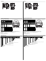
Einstellen der Knotennummer
Die Einstellung der Knotennummer erfolgt mittels der beiden Hexadezimalschalter x16 und x1.
Der Bereich möglicher Knotennummern ist 1 ... 239. Die eingestellte Knotennummer errechnet sich zu:
Knotennummer = Dezimalwert[Schalter x16] x 16 + Dezimalwert[Schalter x1] x 1
Beispiel:
[Schalter x16] = A, [Schalter x1] = 5
Ahex = 10dez x 16 = 160 + 5 = 165
Anzeigen und Bedienelemente
LED Farbe Status Bedeutung
LS/DA 1 grün ein LINK aktiv für HUB Port 1
blinkt Aktivität an HUB Port 1
LS/DA 2 grün ein LINK aktiv für HUB Port 2
blinkt Aktivität an HUB Port 2
LED Farbe Status Bedeutung
Error rot ein - unerlaubte Knotennummer
- interner kommunikationsfehler
- Puffer Leer- oder Überlauf
- Datenkollision
- CRC-Fehler
- SoC-Verlust
aus kein Fehler
Status grün aus inaktiv
flackert Basic Ethernet Mode
blinkt 1x Pre-Operational 1
blinkt 2x Pre-Operational 2
blinkt 3x betriebsbereit
ein Operational
blinkt Stopped
Bestellbezeichnung
E S S 5 8 N – P Z R 0 B N – 0 0
Anzahl der Bits Singleturn
13 8192 (Standard)
16 65536
Temp.
Nnormal
Ausgabecode
BBinär
Option
0keine
Abgang
Rradial
Anschlussart/Protokoll
PZ Powerlink-Protokoll, 2 Buchsen/1 Stecker, M12 x 1
Wellenmaß
F1A Steckhohlwelle Ø10 mm x 30 mm
F2A Steckhohlwelle Ø12 mm x 30 mm
F3A Steckhohlwelle Ø15 mm x 30 mm
Gehäusematerial
NAluminium, pulverbeschichtet
WAluminium, pulverbeschichtet mit Wellendichtung
Funktionsprinzip
SSingleturn
Wellenausführung
SSteckhohlwelle
Datenformat
EEthernet
0
1
2
E
D
C
B
A
3
4
5
6
7
8
9
F
0
1
2
E
D
C
B
A
3
4
5
6
7
8
9
F
POWERLINK
LS/DA 1
Error
Port1 Port2Power
x16 x1
LS/DA 2
Status
Node-
number
LED-Fenster
Knotennummer
Ethernet-PortVersorgungEthernet-Port
LEDs for HUB Port
LEDs for Powerlink
Node number adjustment
The setting of the controlled node number is achieved by 2 hexadicimal switches x16 and x1.
Allowed node numbers range is 1 ... 239. The adjusted node number is calculated as follows:
Node number = Decimal value[switch x16] x 16 + Decimal value[switch x1] x 1
Example:
[switch x16] = A, [switch x1] = 5
Ahex = 10dec x 16 = 160 + 5 = 165
Indicators and operation means
LED Color Status Meaning
LS/DA 1 green on LINK active for HUB Port 1
blinking Activity on HUB Port 1
LS/DA 2 green on LINK active for HUB Port 2
blinking Activity on HUB Port 2
LED Color Status Meaning
Error red on - not allowed node number
- internal communication error
- buffer underrun/overflow
- collision
- CRC error
- loss of SoC
off no error
Status green off not active
flickering Basic Ethernet mode
flashes 1x Pre-Operational 1
flashes 2x Pre-Operational 2
flashes 3x ready to operate
on Operational
blinking Stopped
Order code
E S S 5 8 N – P Z R 0 B N – 0 0
Number of bits singleturn
13 8192 (standard)
16 65536
Temp.
Nnormal
Output code
Bbinary
Option
0none
Exit position
Rradial
Connection type / protocol
PZ Powerlink protocol, 2 female connectors/1 male connector, M12 x 1
Shaft dimensions
F1A Recessed hollow shaft Ø10 mm x 30 mm
F2A Recessed hollow shaft Ø12 mm x 30 mm
F3A Recessed hollow shaft Ø15 mm x 30 mm
Housing material
NAluminium, powder coated
WAluminium, powder coated with shaft seal
Function principle
SSingleturn
Shaft version
SRecessed hollow shaft
Data format
EEthernet
0
1
2
E
D
C
B
A
3
4
5
6
7
8
9
F
0
1
2
E
D
C
B
A
3
4
5
6
7
8
9
F
POWERLINK
LS/DA 1
Error
Port1 Port2Power
x16 x1
LS/DA 2
Status
Node-
number
LED window
Ethernet PortSupplyEthernet Port
Node number
max. Wellen-
einstecktiefe = 30
min. Wellen-
einstecktiefe = 15
Anlagekante an
Momentenstütze
20°
R 1.6
ø 63
72
20
27.5
L
ø 58
75.9
12.7
ø 59
4
1.5
40
60
L: Singleturn = 87
Multiturn = 98
max. insertion
depth = 30
min. insertion
depth = 15
Lay-on edge
torque rest
20°
R 1.6
ø 63
72
20
27.5
L
ø 58
75.9
12.7
ø 59
4
1.5
40
60
L: Singleturn = 87
Multiturn = 98
-
 1
1
-
 2
2


Pepperl+Fuchs ESS58-PZ Bedienungsanleitung
- Typ
- Bedienungsanleitung
in anderen Sprachen
Verwandte Artikel
-
Pepperl+Fuchs ESM58-PZ Bedienungsanleitung
-
-
-
-
-
-
-
-
-
Andere Dokumente
-
Baumer GBMMW Bedienungsanleitung
-
Baumer BMSV 58S flexible Datenblatt
-
-
-
Baumer GBAMS Installation and Operating Instructions
-
-
-
-