
56
min. 158
2
96
128
90 1
39,6
112
59 -1
+
25
1a
2a
(8300004)
8300005
side adjustment
Winkelverstellung
Angle adjustment
Seitenverstellung
Seitenverstellung
Adapter-Fixierung +
side adjustment
Adapter fixing +
B
160
22
192 4
37
37
(62000520)
39
Spax ø5
optional art.nr.
62000516
DIN 7985A
Spax ø4
DIN 931 oder
Schraube M6
the mounting of the ball bearing drawerslide.
128 128
Einschlagmutter M6
are the following dimensions necessary for
at the nominal lengths 400mm and 450mm
der Kugelführung erforderlich
sind folgende Maße zur Befestigung
000003430
bei den Nennlängen 400mm und 450mm
62000519
8300001
änderung vom:
Options
2 art. nr.: 7100069
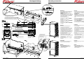
Montageanleitung Mounting instruction
Art.Nr. 000003430
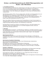
(Illustration ).
Also check that the Allen Head setscrews
are backed out far enough (Illustration ).
+ Insert the slide-out unit all the way to the
end stop.
+ Close safety clip on the U-prfile of the
Top Guide (Illustration ).
Tighten the Allen Head setscrews at the
same time adjusting the side to side
position (Illustration ).
+ Adjust the angle position on the FR 777 as
per (Illustration ).
+ Do not lubricate any part of the slide at
any time !
+ Easy-close damping-system
consisting off
( 6200519 + 520, 8300004 + 05,
620516, 8300001 )
befestigen.
verwenden Sie am hinteren
Befestigungspunkt von FR 777, wegen der
hohen Belastbarkeit (200 kg), unbedingt
M6 Schrauben (DIN 931 o. DIN 7985A)
und Einschlagmuttern.
+ Gegenführung am Korpus lt.
Einbauzeichnung und
befestigen.
+ Adapter am Auszugsmodul lt.
Einbauzeichnung und
befestigen.
+ U-Profil am Auszugsmodul lt.
Einbauzeichnung und
befestigen.
+ Die folgenden Einstellungen sind
6200516, 8300001)
( 6200519 + 520, 8300004 + 05,
bestehend aus
+ Easy-Close Dämpfungssystem
dürfen nicht geschmiert werden.
+ Die Laufbahnen der Führung FR 777
einstellen.
+ Winkelverstellung am FR 777 (Fig. )
Seitenverstellung.
(Fig. ) eindrehen, ist gleichzeitig auch
+ Inbusschrauben für die Adapter-Fixierung
Gegenführung schließen (Fig. ).
+ Aushängesicherung am U-Profil der
Anschlag aufschieben.
+ Auszugsmodul einsetzen und bis zum
die Adapter-Fixierung (Fig. ) offen sind.
ist (Fig. ) und die Inbusschrauben für
Art.Nr. 000003430
Optionen
Zu beachten:
B
B
A
B
B
A
Einsetzen
4, 2a Bohrbild 4b
3, 1a Bohrbild 3b
2, 2a Bohrbild
Wichtig:
Bohrbild 1b
1,1a
Befestigung
Winkelverstellung am FR 777 ganz unten
Gegenführung offen ist (Fig. ), die
die Aushängesicherung am U-Profil der
Bitte prüfen Sie vor dem Einsetzen, daß
werkseitig bereits eingestellt:
+ FR 777 Differenzial-Kulissenauszug am
Korpus lt. Einbauzeichnung und + FR 777 Progressive-Action Pantry-Pullout
Drawerslide mounts in cabinet as per
drawing and according to the
It is essential, due to the high
weight capacity of 450 lb, that on the back
mounting points M6 screws (DIN 931 or
7985A) and matching insert-nuts are being
used.
+ The Top Guide mounts as per drawing
and the
+ The Adapter mounts as per drawing
and the
+ The U-Profile of theTop Guide mounts as
per drawing and the
+ The following adjustments should already
be pre-adjusted:
Please check before inserting slide-out
unit that the safety-clip on the U-profile of
the Top Guide is open (Illustration ) and
the angle-adjustment is all the way down
Mounting
1,1a
drill-pattern 1b
Important:
2, 2a drill-pattern
3, 1a
drill-pattern 3b
4, 2a drill-pattern 4b
Installation
A
B
B
A
B
B
Important:
ausgabe vom: 04-12-14 / t j
3
1
4
3
2offen
Aushängesicherung
Safety-clip
close
open
geschlossen
A
-
 1
1

Hafele 421.50.766 Installationsanleitung
- Typ
- Installationsanleitung
- Dieses Handbuch ist auch geeignet für
Sonstige Unterlagen
-
Venjakob X6 hanging lowboard Assembly Instructions
-
Garant workbench assemblies Bedienungsanleitung
-
E-flite Habu 32 EDF ARF Benutzerhandbuch
-
 BADU Wall nozzle, 5 nozzles, 19 mm each Bedienungsanleitung
-
Torqeedo Throttle Bedienungsanleitung
-
-
-
-
Wincor Nixdorf BEETLE /iSCAN EASY eXpress+ Installationsanleitung
-
AIR-WOLF 10-086 Benutzerhandbuch
