
1
EN INSTALLATION
INSTRUCTIONS
Attention.
Before installing the unit, carefully read
the “WARNINGS FOR INSTALLATION”
contained in the package.
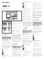
DC POWER SUPPLIER 001DC008AC
It consist of a card onto which there are
the rectifier and the stabilizer.
It is capable of supplying 1.7A at 17.5V DC
and is protected against overloading and
short circuiting.
The 001DC008AC can also be used as a
supplementary power supply whenever
the system requires it.
NOTE. When designing the installation cal-
culate the number of power suppliers in
relation to the total power consumption of
all devices in the system.
001DC008AC
IISTRUZIONI PER
L’INSTALLAZIONE
Attenzione.
Prima di procedere all’installazione
dell’apparecchio leggere attentamente
le “AVVERTENZE PER L’INSTALLAZIONE”
contenute nella confezione.
ALIMENTATORE 001DC008AC
È composto da una scheda in cui ci sono il
raddrizzatore e lo stabilizzatore.
È in grado di erogare 1,7A a 17,5Vcc ed
è protetto contro i sovraccarichi ed i
cortocircuiti. Il 001DC008AC può essere
utilizzato anche come alimentatore sup-
plementare qualora le necessità dell’im-
pianto lo richiedano.
NOTA. In fase di progettazione dell’im-
pianto, calcolare il numero degli alimen-
tatori in funzione dell’assorbimento delle
varie apparecchiature installate.
Funzione dei morsetti (fig.1)
Morsettiera G
rete
Morsettiera A
1 + uscita 17,5V
2 –
1 + uscita 17,5V
2 –
Caratteristiche tecniche
• Alimentazione: 230Vca 50/60Hz.
Protezione elettrica autoripristinabile.
1
A
G
2121
43,5
45
7,5 57
140
106
A
B
64,5
140
145
2
24807070/11-07-2013
DINSTALLATIONS-
ANLEITUNG
ACHTUNG.
Um Verletzungen zu vermeiden,
muss dieses Gerät entsprechend den
Installationsanweisungen an der
Wand abgesichert sein.
NETZGERÄT 001DC008AC
Besteht aus einer Platine, auf der ein
Gleichrichter und ein Stabilisator ange-
bracht sind.
Er kann 1,7A bei 17,5V DC versorgen
und ist gegen Überlast und Kurzschluß
geschützt.
Das 001DC008AC kann als Zusatzversor-
gung Anwendung finden, wenn dieses
infolge besonderer Anlagenverhältnisse
erforderlich sein sollte.
ANMERKUNG. Bei Projektierung der
Anlage die Anzahl der Netzgeräte in
Abhängigkeit von der Stromaufnahme
der verschiedenen installierten Geräte
berechnen.
Belegung der Klemmleisten (Abb.1)
Klemmleiste G Klemmleiste G
Netz
Klemmleiste A
1 +Ausgang 17,5V
2 –
1 +Ausgang 17,5V
2 –
Technische Daten
• Spannungsversorgung: 230V AC
50/60 Hz. Selbst rückstellbarer elekt-
rischer Schutz.
• Stromaufnahme:Imax =250 mA
AC
AC
• Verlustleistung: 10W max
• Ausgangsspannung: 17,5V 1,7A in
Dauerbetrieb.
• Betriebstemperatur: von 0 °C bis +35
°C.
CAME Group S.p.A
Viale delle Industrie, 89/c
31030 Dosson di Casier-TREVISO-Italy
www.came.it[email protected]
• Corrente assorbita: Imax =250 mA AC
AC
• Potenza dissipata: 10W max
• Tensione di uscita: 17,5Vcc, 1,7A in
servizio continuo.
• Temperatura di funzionamento: da 0
°C a +35 °C.
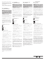
• Dimensioni: modulo da 8 unità basso
(fig. 1).
L’apparecchio può essere installato, senza
coprimorsetti, in scatole munite di guida
DIN (EN 50022).
Per le dimensioni di ingombro vedere
la fig. 2A.
Oppure può essere installato a parete
utilizzando la guida DIN in dotazione,
applicando il coprimorsetti ed eventuali
tasselli in dotazione.
Per le dimensioni d’ingombro vedere la
fig. 2B.
NOTA. La protezione dell’apparecchio
contro sovraccarichi e cortocircuiti è otte-
nuta mediante un interruttore termico
autoripristinabile, inserito sul primario del
trasformatore di alimentazione.
Dopo l’intervento della protezione, il ripri-
stino del funzionamento avviene auto-
maticamente dopo che la temperatura
del trasformatore scende al di sotto dei
85 °C.
Accertare ed eliminare le cause che hanno
determinato l’intervento della protezione.
Function of each terminal (fig.1)
Terminal block G
mains
Terminal block A
1 + 17,5V output
2 –
1 + 17,5V output
2 –
Technical features
• Mains supply: 230V AC 50/60Hz. Self-
resetting electric safety switch.
• Input current: Imax =250 mA
AC
AC
• Dissipated power: 10W max
• Output voltage: 17.5V DC 1.7A con-
tinuous current demand.
• Working temperature range: from 0 °C
to +35 °C.
• Dimensions: 8 DIN units, low profile
module, figure 1.
The equipment can be installed without
terminal covers into boxes provided with
DIN rail (EN 50022).
Dimensions are shown in figure 2A.
Or it can be wall-mounted using the DIN
rail provided, applying as necessary the
terminal covers and plugs provided.
Dimensions are shown in figure 2B.
NOTE. The unit is protected against over-
loads and short-cicuits by a self-resetting
thermal switch, inserted on the primary of
the power supply transformer. Once the
switch trips, operation is resumed automati-
cally once the temperature of the transform-
er drops back below 85 °C. Make sure the
cause of the switch tripping is eliminated.
• Abmessungen: 8 DIN-Einheiten, flach
(Abb. 1).
Nach Entfernung der Klemmabdec-
kungen lassen sich diese Geräte auf DIN-
Montageschienen in Verteilerkästen mon-
tieren (EN 50022).
Maßangaben, siehe Abb. 2A.
Kann aber auch mit Hilfe der beilie-
genden DIN-Schiene an der Wand
befestigt werden, hierfür beiliegende
Klemmenabdeckungen und eventuell
Dübel verwenden. Maßangaben, siehe
Abb. 2B.
HINWEIS. Der Geräteschutz gegen
Kurzschluß und Überlastung besteht
aus einem selbst rückstellbaren
Wärmeschalter, der sich auf der
Primärspule des Leistungstransfor-mators
befindet.
Die erneute Betriebsaufnahme erfolgt
automatisch nach dem Schutzeingriff
und nach dem Absinken der Temperatur
des Transformators unter 85 °C.
Die Ursachen, die den Schutz auslösten,
herausfinden und behenden.
FR INSTRUCTIONS
POUR L’INSTALLATION
Attention.
Avant de procéder à l’installation
de l’appareil, lire attentivement
les “RECOMMANDATIONS POUR
L’INSTALLATION” contenues dans la
boîte.
ALIMENTATION 001DC008AC
Se compose d’une carte de redressement
et stabilisation de tension.
Protégée contre le surcharges et courts-
circuits, peut fournir un courant de 1,7A
sous 17,5Vcc. La 001DC008AC peut éga-
lement être employée comme alimenta-
tion supplémentaire.
NOTE. En phase d’étude de l’installation
calculer le nombre des alimentations en
fonction de l’absorption des différentes
appareils prévus.
Fonction des bornes (fig.1)
Bornier G
secteur
Bornier A
1 + sortie 17,5V
2 –
1 + sortie 17,5V
2 –
Caractéristiques techniques
• Alimentation: 230Vca 50/60 Hz.
Protection électrique à réarmement
automatique.
• Courant absorbé:Imax =250 mA
AC
AC
• Puissance dissipée: 10W max
• Tension de sortie: 17,5Vcc, 1,7A en
service continu.
• Température de fonctionnement: de 0
°C à +35 °C.
• Dimensions: module de 8 unités bas
(fig. 1).
L’appareil peut être installé sans couvre-
borniers dans des armoires DIN avec rail
EN 50022 (voir fig. 2A). Ou bien il peut être
installé au mur en utilisant le guide DIN
fourni et en appliquant le cache-bornes
et les éventuelles chevilles fournies (voir
fig. 2B).
NOTE. La protection de l’appareil contre
les surcharges et les courts-circuits s’ob-
tient à l’aide d’un interrupteur thermique
à réarmement automatique, inséré sur
le primaire du transformateur d’alimen-
tation.

2
ES INSTRUCCIONES
PARA LA INSTALACION
Atención.
Antes de comenzar la instalación
del aparato, leer detenidamen-
te las “ADVERTENCIAS PARA LA
INSTALACIÓN” que se incluyene en el
embalaje.
ALIMENTADOR 001DC008AC
El alimentador está formado por un tran-
sformador de 60VA y por una tarjeta dota-
da de rectificador y estabilizador.
Es capaz de generar de 1,7A a 17,5Vcc
y está protegido contra sobrecargas y
cortocircuitos.
El 001DC008AC se puede utilizar como
alimentador suplementario cuando las
necesidades del equipo lo requieran.
NOTA. En la fase de projecto del equipo se
debe calcular el número de alimentadores
en función de la absorción de los aparatos
instalados.
Funciones de los bornes (fig.1)
Bornera G
red
Bornera A
1 + salida 17,5V
2 –
1 + salida 17,5V
2 –
Características técnicas
• Alimentación: 230V 50/60 Hz.
Protección eléctrica con autoreactiva-
ción.
•
Corriente absorbida
:Imax =250 mA AC
AC
• Potencia disipada: 10W max
• Tensión de salida: 17,5Vcc, 1,7A en
servicio continuo.
• Temperatura de funcionamiento: de 0
°C a +35 °C.
• Dimensiones: módulo de 8 unidades
bajo para guía DIN (fig. 1).
El aparato se puede instalar, sin cubre-
bornes, en cajas dotadas de guías DIN
(EN 50022).
Por las dimensiones consultar la fig. 2A.
También se puede instalar a pared usan-
do la guía DIN que se suministra, aplica-
do el cubre-bornes y los posibles tacos
entregados.
Por las dimensiones consultar la fig. 2B.
NOTA. La protección del aparato contra
sobrecargas y cortocicuitos se obtiene
mediante un interruptor térmico de auto-
reactivación, colocado en el primario del
transformador de alimentación.
Después de haber realizado la operación
de protección, y de que la temperatura
del transformador haya descendido por
debajo de los 85 °C, automaticamente
se produce la reactivación del funciona-
miento.
PT INSTRUÇÕES
PARA A INSTALAÇÃO
Atenção.
Antes de efectuar a instalação do
aparelho leia com atenção os “AVISOS
PARA A INSTALAÇÃO” contidos na
embalagem.
ALIMENTADOR 001DC008AC
É composto por um transformador de
60VA e por uma carta electrónica em
que se encontram o retificador e o esta-
bilizador.
Está em condições de fornecer 1,7A a
17,5Vcc e é protegido contra as sobrecar-
gas e os curtos-circuitos.
O 001DC008AC pode ser utilizado tam-
bém como alimentador suplementar, se
for preciso.
NOTA. Na fase de projecto da instalação,
calcular o número dos alimentadores em
função do consumo dos vários aparelhos
instalados.
Função dos bornes (fig.1)
Placa de bornes G
rede
Placa de bornes A
1 +saída 17,5V
2 –
1 +saída 17,5V
2 –
Características técnicas
• Alimentação: 230V 50/60 Hz.
Protecção eléctrica com estabeleci-
mento automático.
• Corrente consumida: Imax =250 mA
AC
AC
• Potência dissipada: 10W max
• Tensão de saída: 17,5Vcc, 1,7A em
serviço contínuo.
• Temperatura de funcionamento: de 0
°C a +35 °C.
• Dimensões: módulo de 8 unidades
baixo para calha DIN (fig. 1).
O aparelho pose ser instalado, sem a
tampa dos bornes, em caixas com calha
DIN (EN 50022).
Para as dimensões ver fig. 2A.
Ou pode ser instalado na parede utili-
zando a guia DIN fornecida, aplicando
a tampa dos bornes e eventuais buchas
fornecidas.
Para as dimensões ver fig. 2B.
NOTA. A protecção do aparelho contra
as sobrecargas e curtos-cicuitos obtém-
se mediante um interruptor térmico com
restabelecimento auto-mático, inserido
no primário do trasformador de alimen-
tação.
Depois da intervenção da protecção, o
restabelecimento do funcionamento
verifica-se automaticamente logo que a
temperatura do transformador desça aos
85 °C.
Avaliar e eliminar as causas que determi-
naram a intervenção da protecção.
Après l’intervention de la protection, le
réarmement du fonctionnement s’effec-
tue automatiquement dès que la tem-
pérature du transformateur descend au-
dessous de 85 °C.
Chercher et éliminer les causes qui ont
provoqué l’intervention de la protection.
NL INSTRUCTIES VOOR DE
INSTALLATIE
Let op.
Voordat u het toestel installeert, lees
aandachtig de “WAARSCHUWINGEN
VOOR DE INSTALLATIE” die zich in de
verpakking bevinden.
VOEDING 001DC008AC
De voeding bestaat uit een kaart waarop
zich de gelijkrichter en de stabilisator
bevinden.
Hij levert 1,7A aan 17,5Vcc en is
beschermd tegen overbelasting en
kortsluiting. 001DC008AC kan ook gebru-
ikt worden als bijkomende voeding wan-
neer de installatie dit vereist.
OPMERKING. Bereken tijdens de
ontwerpfase van de installatie het aantal
voedingen op basis van de verschillende
toestellen die geïnstalleerd worden.
De klemmen (fig.1)
Klemmenbord G
net
Klemmenbord A
1 + uitgang 17,5V
2 –
1 + uitgang 17,5V
2 –
Technische specificaties
• Voeding: 230Vca 50/60Hz Automatisch
herstelbare elektrische bescherming.
• Geabsorbeerde
stroom: Imax =250 mA
AC
AC
• Verbruikt vermogen: 10W max
• Uitgangsspanning: 17,5Vcc, 1,7A
gelijkstroom.
• Werkingstemperatuur: van 0 °C tot
+35 °C.
• Afmetingen: module van 8 eenheden
met laag profiel (fig. 1).
Het toestel kan zonder klembeschermers
geïnstalleerd worden in dozen die uitge-
rust zijn met een DIN-profiel (EN 50022).
Zie fig. 2A voor de afmetingen.
Het toestel kan ook aan de wand wor-
den gemonteerd met behulp van het
bijgeleverde DIN-profiel, met de klembe-
schermers en de eventueel bijgeleverde
pluggen.
Zie fig. 2B voor de afmetingen.
OPMERKING. Het toestel is beschermd
tegen overbelasting en kortsluiting dank-
zij een automatisch herstelbare thermi-
sche schakelaar die zich op hoofdleiding
van de voedingstransformator bevindt.
Nadat de bescherming in werking is
getreden, wordt de werking automatisch
hersteld wanneer de temperatuur van de
transformator lager is dan 85 °C.
Controleer en verwijder de oorzaken die
de bescherming in werking hebben doen
treden.
RU РУКОВОДСТВО ПО
УСТАНОВКЕ
Внимание.
Перед установкой устройства
внимательно ознакомьтесь с
“ПРИМЕЧАНИЯМИ К УСТАНОВКЕ”,
содержащимися в упаковке.
БЛОК ПИТАНИЯ ПОСТ. ТОКА VAS/100.30
Устройство состоит из платы, на кото-
рой установлены выпрямитель и ста-
билизатор. Выходное напряжение - 17.5
В пост. тока 1,7 A оснащен электрон-
ной защитой от перегрузок и корот-
ких замыканий. При необходимости
001DC008AC может быть использован
как дополнительный источник питания.
ПРИМЕЧАНИЕ. При проектировании
системы необходимо рассчитать
количество блоков питания исходя
из общего энергопотребления всех
устройств.
Панель выводов (рис. 1)
Клеммная колодка G
Сеть электропитания
Клеммная колодка A
1 + 17,5 В пост. тока
2 –
1 + 17,5 В пост. тока
2 –
Технические характеристики
• Питание: 230 В пер. тока 50/60Гц.
Самовозвратный электрический пре-
дохранитель.
• Потребляемый
ток: Iмax =250 мA AC
AC
• Рассеиваемая мощность: 10W max
• Выходное напряжение: 17.5 В пост.
тока 1.7 A (длительное потребление).
• Рабочая температура: от 0 до +35°C
• Размеры: 8 DIN единиц, низкопро-
фильный модуль, рисунок 1.
Устройство может быть установлено
на DIN-рейку (EN 50022) в монтажном
шкафу. Размеры указаны на рис. 2A.
Также устройство может быть установ-
лено на стену с использованием защит-
ных крышек клеммной колодки.
Размеры указаны на рис. 2B.
ПРИМЕЧАНИЕ. Устройство защищено
от перегрузок и коротких замыканий
самовозвратным тепловым предохра-
нителем, установленным в первичной
обмотке трансформатора питания..
После срабатывания предохранителя,
работа будет восстановлена авто-
матически, как только температура
трансформатора упадет ниже 85 ° С.
Убедитесь, что причины срабатыва-
ния предохранителя устранены.
-
 1
1
-
 2
2


in anderen Sprachen
- italiano: CAME DC008AC Guida d'installazione
- Nederlands: CAME DC008AC Installatie gids
- português: CAME DC008AC Guia de instalação