Parkside PBS 350 A1 Operating And Safety Instructions Manual
- Typ
- Operating And Safety Instructions Manual

IAN 292291
BAND SAW PBS 350 A1
NIIEGB
NIIE
BAND SAW
Operating and Safety Instructions
Translation of Original Operating Manual
GB
CHAT
BANDSÄGE
Bedienungs- und Sicherheitshinweise
Originalbetriebsanleitung
DE

GB / IE / NI Operation and Safety Notes Page 01
DE / AT / CH Bedienungs- und Sicherheitshinweise Seite 12
Klappen Sie vor dem Lesen die Seite mit den Abbildungen aus und machen Sie sich anschließend mit allen Funktionen des Gerätes vertraut.
DE AT CH
Before reading, unfold the page containing the illustrations and familiarise yourself with all functions of the device.
GB IE NI

GB IE NI
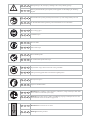
Read and follow the operating and safety instructions before you start working with this power tool!
DE AT CH
Vor Inbetriebnahme Bedienungsanleitung und Sicherheitshinweise lesen und beachten!
GB IE NI
Wear safety goggles!
DE AT CH
Schutzbrille tragen!
GB IE NI
Important! Risk of injury! Never reach into the running saw blade!
DE AT CH
Achtung! Verletzungsgefahr! Nicht in das laufende Sägeblatt greifen!
GB IE NI
Wear protective gloves.
DE AT CH
Tragen Sie Schutzhandschuhe.
GB IE NI
Attention! Before installation, cleaning, alterations, maintenance, storage and transport switch off the
device and disconnect it from the power supply.
DE AT CH
Achtung! Vor Montage, Reinigung, Umbau, Instandhaltung, Lagerung und Transport müssen Sie das
Gerät ausschalten und von der Stromversorgung trennen.
GB IE NI
Wear ear-muffs!
DE AT CH
Gehörschutz tragen!
GB IE NI
Wear a breathing mask!
DE AT CH
Bei Staubentwicklung Atemschutz tragen!
GB IE NI
Attention! Observe the direction of rotation.
DE AT CH
Achtung! Drehrichtung beachten.
m
GB IE NI
Warning! Danger to life, risk of injury or damage to the tool are possible by ignoring!
DE AT CH
Warnung! Bei Nichteinhaltung Lebensgefahr, Verletzungsgefahr oder Beschädigung des Werkzeugs
möglich!

1a
1b
1c
1d
1
2
3
4
5
6
7
3
8
9
10
11
10
10
11
10
13
14
15
16
17
18
19
20
21
22
23
30
29
27 28 51
2425
7
26
12

2
3
4
5
6
8
9
1731
20
32
33
33
34
32
7
20
31
35
36
37
3838
3739
44
45
45
46
46
47
43
23
5
22
7
41
42
40
21
21
21

15
16
14
12
48
26
13
6
24
21
25
10
5
21
11
49
50
12
7
7
7

19
17
18

GB/IE/NI
1
Table of contents: Page:
1. Introduction 2
2. Device description 2
3. Scope of delivery 2
4. Intended use 3
5. General safety information 3
6. Technical data 5
7. Remaining hazards 5
8. Before starting the equipment 5
9. Attachment 6
10. Operation 7
11. Transport 8
12. Working instructions 8
13. Cleaning and maintenance 9
14. Storage 9
15. Electrical Connection 9
16. Disposal and recycling 9
17. Troubleshooting 10
18. Guarantee certificate 11
19. Declaration of conformity 25

GB/IE/NI
2
1. Introduction
Manufacturer:
scheppach
Fabrikation von Holzbearbeitungsmaschinen GmbH
Günzburger Straße 69
D-89335 Ichenhausen
Dear Customer,
We hope your new tool brings you much enjoyment and suc-
cess.
Note:
According to the applicable product liability laws, the manu-
facturer of the device does not assume liability for damages
to the product or damages caused by the product that occurs
due to:
• Improper handling,
• Non-compliance of the operating instructions,
• Repairs by third parties, not by authorized service techni-
cians,
• Installation and replacement of non-original spare parts,
• Application other than specified,
• A breakdown of the electrical system that occurs due to
the non-compliance of the electric regulations and VDE
regulations 0100, DIN 57113 / VDE0113.
We recommend:
Read through the complete text in the operating instructions
before installing and commissioning the device. The operating
instructions are intended to help the user to become familiar
with the machine and take advantage of its application pos-
sibilities in accordance with the recommendations. The op-
erating instructions contain important information on how to
operate the machine safely, professionally and economically,
how to avoid danger, costly repairs, reduce downtimes and
how to increase reliability and service life of the machine.
In addition to the safety regulations in the operating instruc-
tions, you have to meet the applicable regulations that apply
for the operation of the machine in your country. Keep the op-
erating instructions package with the machine at all times and
store it in a plastic cover to protect it from dirt and moisture.
Read the instruction manual each time before operating the
machine and carefully follow its information. The machine can
only be operated by persons who were instructed concerning
the operation of the machine and who are informed about the
associated dangers. The minimum age requirement must be
complied with. In addition to the safety requirements in these
operating instructions and your country’s applicable regula-
tions, you should observe the generally recognized technical
rules concerning the operation of woodworking machines.
We cannot accept any liability for damage or accidents
which arise due to a failure to follow these instructions and
the safety instructions.
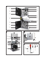
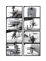
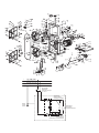
2. Device description (Fig. 1-16)
1. Clamping screw
2. Top saw band roller
3. Rubber surface
4. Saw band guard
5. Top saw band guide
6. Table insert
7. Saw table
8. Bottom saw band roller
9. Foot
10. Cover locking mechanism
11. Side cover
12. On/off switch
13. Locking screw for top saw band roller
14. Set screw for top saw band roller
15. Machine frame
16. Mains cable
17. Degree scale for swivel range
18. Motor
19. Extraction nozzle
20. Locking handle for saw table
21. Bandsaw blade
22. Adjustment handle for saw band guide
23. Locking handle for saw band guide
24. Parallel stop
25. Clamping bar for parallel stop
26. Push stick
27. 3 mm Allen key
28. 4 mm Allen key
29. Screwdriver
30. Open-ended spanner
31. Wing nut
32. Clamping plate
33. Knurled nut
34. U-reinforcement
35. Allen screw for top support bearing
36. Top support bearing
37. Top guide pin
38. Allen screw for top guide pins
39. Retainer (top)
40. Allen screw top retainer (2x)
41. Allen screw bottom support bearing
42. Bottom support bearing
43. Screw bottom retainer
44. Saw band protection
45. Allen screw for bottom guide pins
46. Bottom guide pin
47. Retainer (bottom)
48. Push Stick retainer
49. Screw (saw table adjustment)
50. Nut (saw table adjustment)
51. 5 mm Allen key
3. Scope of delivery
• Open the packaging and remove the device carefully.
• Remove the packaging material as well as the packaging
and transport bracing (if available).
• Check that the delivery is complete.

GB/IE/NI
3
• Check the device and accessory parts for transport dam-
age.
• If possible, store the packaging until the warranty period
has expired.
ATTENTION!
The device and packaging materials are not toys! Children
must not be allowed to play with plastic bags, film and small
parts! There is a risk of swallowing and suffocation!
• Bandsaw / Bandsaw blade (pre-assembled)
• Saw table
• Push stick
• Parallel stop
• Open-ended spanner, size 10/13
• Allen key, size 3/4/5
• Screwdriver
• Original operating instructions
4. Intended use
The bandsaw is designed to perform longitudinal and cross
cuts on timber or wood-type materials. To cut round materi-
als you must use suitable holding devices.
The equipment is to be used only for its prescribed purpose.
Any other use is deemed to be a case of misuse. The user /
operator and not the manufacturer will be liable for any dam-
age or injuries of any kind caused as a result of this.
The machine is to be operated only with suitable saw blades.
To use the machine properly you must also o serve the safety
regulations, the assembly instructions and the operating in-
structions to be found in this manual.
All persons who use and service the machine have to be ac-
quainted with this manual and must be informed about the
machine’s potential hazards. It is also imperative to observe
the accident prevention regulations in force in your area. The
same applies for the general rules of occupational health
and safety.
The manufacturer shall not be liable for any changes made to
the machine nor for any damage resulting from such changes.
Even when the machine is used as prescribed it is still impos-
sible to eliminate certain residual risk factors. The following
hazards may arise in connection with the machine’s construc-
tion and design:
• Damage to hearing if ear-muffs are not used as necessary.
• Harmful emissions of wood dust when used in closed
rooms.
• Contact with the blade in the uncovered cutting zone.
• Injuries (cuts) when changing the blade.
• Injury from catapulted workpieces or parts of workpieces.
• Crushed fingers.
• Kickback.
• Tilting of the workpiece due to inadequate support.
• Touching the blade.
• Catapulting of pieces of timber and workpieces.
Please note that our equipment has not been designed for use
in commercial, trade or industrial applications. Our warranty
will be voided if the machine is used in commercial, trade or
industrial businesses or for equivalent purposes.
5. General safety information
Attention! The following basic safety measures must be ob-
served when using electric tools for protection against electric
shock, and the risk of injury and fire. Read all these notices
before using the electric tool and keep the safety instructions
for later reference.
Safe work
1 Keep the work area orderly
– Disorder in the work area can lead to accidents.
2 Take environmental influences into account
– Do not expose electric tools to rain.
– Do not use electric tools in a damp or wet environment.
– Make sure that the work area is well-illuminated.
– Do not use electric tools where there is a risk of fire or
explosion.
3 Protect yourself from electric shock
– Avoid physical contact with earthed parts (e.g. pipes,
radiators, electric ranges, cooling units).
4 Keep children away
– Do not allow other persons to touch the equipment or
cable, keep them away from your work area.
5 Securely store unused electric tools
– Unused electric tools should be stored in a dry, elevated
or closed location out of the reach of children.
6 Do not overload your electric tool
– They work better and more safely in the specified output
range.
7 Use the correct electric tool
– Do not use low-output electric tools for heavy work.
– Do not use the electric tool for purposes for which it is
not intended. For example, do not use handheld circular
saws for the cutting of branches or logs.
– Do not use the electric tool to cut firewood.
8 Wear suitable clothing
– Do not wear wide clothing or jewellery, which can be-
come entangled in moving parts.
– When working outdoors, anti-slip footwear is recommended.
– Tie long hair back in a hair net.
9 Use protective equipment
– Wear protective goggles.
– Wear a mask when carrying out dust-creating work.
10 Connect the dust extraction device if you will be process-
ing wood, materials similar to wood, or plastics.
– If connections for dust extraction and a collecting de-
vice are present, make sure that they are connected
and used properly.
– When processing wood, materials similar to wood, and
plastics. Operation in enclosed spaces is only permit-
ted with the use of a suitable extraction system.
11 Do not use the cable for purposes for which it is not
intended
— Do not use the cable to pull the plug out of the outlet.
Protect the cable from heat, oil and sharp edges.
12 Secure the workpiece
– Use the clamping devices or a vice to hold the work-
piece in place. In this manner, it is held more securely
than with your hand.

GB/IE/NI
4
– An additional support is necessary for long workpieces
(table, trestle, etc.) in order to prevent the machine
from tipping over.
– Always press the workpiece firmly against the working
plate and stop in order to prevent bouncing and twist-
ing of the workpiece.
13 Avoid abnormal posture
– Make sure that you have secure footing and always
maintain your balance.
– Avoid awkward hand positions in which a sudden slip
could cause one or both hands to come into contact
with the saw blade.
14 Take care of your tools
– Keep cutting tools sharp and clean in order to be able
to work better and more safely.
– Follow the instructions for lubrication and for tool re-
placement.
– Check the connection cable of the electric tool regu-
larly and have it replaced by a recognised specialist
when damaged.
– Check extension cables regularly and replace them
when damaged.
– Keep the handle dry, clean and free of oil and grease.
15 Pull the plug out of the outlet
– Never remove loose splinters, chips or jammed wood
pieces from the running saw blade.
– During non-use of the electric tool or prior to mainte-
nance and when replacing tools such as saw blades,
bits, milling heads.
– When the saw blade is blocked due to abnormal feed
force during cutting, turn the machine off and discon-
nect it from power supply. Remove the work piece and
ensure that the saw blade runs free. Turn the machine
on and start new cutting operation with reduced feed
force.
16 Do not leave a tool key inserted
– Before switching on, make sure that keys and adjusting
tools are removed.
17 Avoid inadvertent starting
– Make sure that the switch is switched off when plugging
the plug into an outlet.
18 Use extension cables for outdoors
– Only use approved and appropriately identified exten-
sion cables for use outdoors.
– Only use cable reels in the unrolled state.
19 Remain attentive
– Pay attention to what you are doing. Remain sensible
when working. Do not use the electric tool when you
are distracted.
20 Check the electric tool for potential damage
– Protective devices and other parts must be carefully
inspected to ensure that they are fault-free and function
as intended prior to continued use of the electric tool.
– Check whether the moving parts function faultlessly
and do not jam or whether parts are damaged.
All parts must be correctly mounted and all conditions must
be fulfilled to ensure fault-free operation of the electric tool.
– The moving protective hood may not be fixed in the
open position.
– Damaged protective devices and parts must be prop-
erly repaired or replaced by a recognised workshop,
insofar as nothing different is specified in the operating
manual.
– Damaged switches must be replaced at a customer
service workshop.
– Do not use any faulty or damaged connection cables.
– Do not use any electric tool on which the switch cannot
be switched on and off.
21 ATTENTION!
– The use of other insertion tools and other accessories
can entail a risk of injury.
22 Have your electric tool repaired by a qualified electrician
– This electric tool conforms to the applicable safety regu-
lations. Repairs may only be performed by an electri-
cian using original spare parts. Otherwise accidents
can occur.
Additional safety instructions
• Wear safety gloves whenever you carry out any mainte-
nance work on the blade!
• When cutting round or irregularly shaped wood, use a
device to stop the workpiece from twisting.
• When cutting boards in upright position, use a device to
prevent kick-back.
• A dust extraction system designed for an air velocity of 20
m/s should be connected in order to comply with wood-
working dust emission values and to ensure reliable op-
eration.
• Give these safety regulations to all persons who work on
the machine.
• Do not use this saw to cut fire wood.
• The machine is equipped with a safety switch to prevent it
being switched on again accidentally after a power failure.
• Before you use the machine for the first time, check that
the voltage marked on the rating plate is the same as your
mains voltage.
• If you use a cable reel, the complete cable has to be pulled
off the reel.
• Persons working on the machine should not be distracted.
• Note the direction of rotation of the motor and blade.
• Never dismantle the machineʼs safety devices or put them
out of operation.
• Never cut workpieces which are too small to hold securely
in your hand.
• Never remove loose splinters, chips or jammed pieces of
wood when the saw blade is running.
• It is imperative to observe the accident prevention regula-
tions in force in your area as well as all other generally
recognized rules of safety.
• Note the information published by your professional as-
sociations.
• Adjustable protective devices have to be adjusted as close
as possible to the workpiece.
• Important! Support long workpieces (e.g. with a roller ta-
ble) to prevent them sagging at the end of a cut.
• Make sure the blade guard (4) is in its lower position when
the saw is being transported.
• Safety guards are not to be used to move or misuse the
machine.

GB/IE/NI
5
• Blades that are misshapen or damaged in any way must
not be used.
• If the table insert is worn, replace it.
• Never operate the machine if either the door protecting the
blade or the detachable safety device are open.
• Ensure that the choice of blade and the selected speed are
suitable for the material to be cut.
• Do not begin cleaning the blade until it has come to a
complete standstill.
• For straight cuts of small workpieces against the longitudi-
nal limit stop the push stick has to be used.
• Wear gloves when handling the saw blade and rough
materials
• The bandsaw blade guard should be in its lowest position
close to the bench during transport.
• For miter cuts when the table is tilted, the parallel stop must
be positioned on the lower part of the table.
• Never use guards to lift or transport items.
• Ensure that the bandsaw blade guards are used and cor-
rectly adjusted.
• Keep your hands a safety distance away from the band-
saw blade. Use a push stick for narrow cuts.
• The push stick has to be stored on the intended device, so
that it can be reached from normal working position and
is always ready to be used.
• In the normal operating position the operator is in front
of the machine.
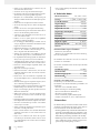
6. Technical data
Electro motor
230 - 240 V ~ 50 Hz
Power S1 250W, S2 30 min 350W
Revolutions n
0
1400 min
-1
Saw band length
1400 mm
Saw band width
3,5-12 mm
Saw band width max.
12 mm
Cutting speed
900 m/min
Passage height
0 - 80 mm
Passage width
200 mm
Table size
300 x 300 mm
Slewing range of the table
0° bis 45°
Max. size of the
workpiece
400 x 400 x 80 mm
Overall weight
16,5 kg
Subject to technical modifications!
* Operating mode S1, continous operation.
* Operating mode S2, short-term operation with constant
load; Duration of nominal operation
The work piece must have a minimum height of 3 mm and a
minimum width of 10 mm.
The total noise values determined in accordance with EN
61029.
Sound pressure level L
pA
77,4 dB(A)
Uncertainty K
pA
3 dB
Sound power level L
WA
90,4 dB(A)
Uncertainty K
WA
3 dB
Wear hearing protection.
The effects of noise can cause a loss of hearing. Keep the
noise level and vibration to a minimum!
• Only use faultless devices.
• Maintain and clean the device at regular intervals.
• Adapt your working methods to the device.
• Do not overload the device.
• Have the device checked if necessary.
• Switch the device off if it is not in use.
7. Remaining hazards
The machine has been built using modern technology in ac-
cordance with recognized safety rules. Some remaining haz-
ards, however, may still exist.
• Risk of injury for fingers and hands by the rotating saw
band due to improper handling of the work piece. Risk of
injury through the hurling work piece due to improper han-
dling, such as working without the push stick.
• Risk of damaging your health due to wood dust and wood
chips. Wear personal protective cloth such as goggles. Use
a fitting dust extractor.
• Risk of injury due to defective saw band. Regularely check
saw band for such defects.
• Risk of injury for fingers and hands while changing saw
band. Wear proper gloves.
• Risk of injury due to starting saw band while switching on
the machine.
• The use of incorrect or damaged mains cables can lead to
injuries caused by electricity.
• Wear only closefitting clothes. Remove rings, bracelets and
other jewelry.
• For the safety of long hair, wear a cap or hair net. Even
when all safety measures are taken, some remaining haz-
ards which are not yet evident may still be present.
• Remaining hazards can be minimized by following the in-
structions in „General safety instructions“ „Proper Use“ and
in the entire operating manual.
8. Before starting the equipment
Make sure the machine stands securely, i.e. bolt it to a
workbench or solid base. There are two holes for this purpose
in the machine foot.
• The saw table must be mounted correctly.
• All covers and safety devices have to be properly fitted
before the machine is switched on.
• It must be possible for the blade to run freely.
• When working with wood that has been processed before,
watch out for foreign bodies such as nails or screws etc.
• Before you actuate the On/Off switch, make sure that the
saw blade is correctly fitted and that the machine’s moving
parts run smoothly.

GB/IE/NI
6
• Before you connect the machine to the power supply, make
sure the data on the rating plate is the same as that for
your mains.
9. Attachment
ATTENTION!
Before all maintenance, set-up and assembly work on the
band saw, unplug the mains plug.
Assembly tools
1 Open-ended spanner, size 10/13
1 Allen key, size 3
1 Allen key, size 4
1 Screwdriver
The saw table is not assembled for packaging reasons.
9.1. Assembling the saw table (Fig. 2-4)
• Remove the wing nut (31), the locking handle (20), the two
washers and the clamping plate (32). (Fig. 2)
• Remove the two knurled nuts (33), the U-reinforcement (34)
and the two countersunk screws M6x16 from the saw ta-
ble. (Fig. 3)
• Guide the saw table (7) over the Bandsaw blade (21).
Fasten it to the two screws on the machine frame with the
plate (32), the two washers, the wing nut (31) and the lock-
ing handle (20). (Fig. 4)
• Fasten the U-reinforcement (34) to the front side of the saw
table with 2 countersunk screws M6x16 and 2 knurled
nuts (33). (Fig.3)
9.2. Tensioning the saw band (Fig. 1a)
• ATTENTION! If the saw is at a standstill for an extended
period the saw band tension must be relieved, i.e. before
switching the saw on it is necessary to check the saw blade
tension.
• Turn the clamping screw (1) clockwise to tension the Band-
saw blade (21). The correct tension of the saw band can
be determined by pressing the finger laterally against the
saw band, roughly centrally between the two saw band
rollers (2+8). The Bandsaw blade (21) should only depress
slightly (approx. 1-2 mm) here.
• The sufficiently tensioned saw band makes a metallic sound
when tapped.
• Relieve the saw band tension if it is not in use for an ex-
tended time, so that it does not become overstretched.
• ATTENTION! With high tension, the saw band may break.
RISK OF INJURY! If the tension is too low, the driven saw
band roller (8) may spin, resulting in the saw band com-
ing to a standstill.
9.3 Adjusting the saw band (Fig. 1a+1b)
• ATTENTION! Before it is possible to implement the saw
band setting, the saw band must be tensioned correctly.
• Open the side covers (11) by undoing the cover locking
mechanisms (10) with the help of the screwdriver (29).
• Slowly turn the saw band roller (2) clockwise. The Band-
saw blade (21) should run centrally on the saw band roller
(2). If this is not the case, the angle of the top saw band
roller (2) must be corrected.
• If the Bandsaw blade (21) runs more towards the rear edge
of the saw band roller (2) then the set screw (14) must be
rotated anticlockwise.
• Open the locking screw for the top saw band roller (13).
• Turn the bottom saw band roller (8) slowly by hand, to
check the position of the Bandsaw blade (21).
• If the Bandsaw blade (21) runs more towards the front
edge of the saw band roller (2) then the set screw (14)
must be rotated clockwise.
• After setting the top saw band roller (2), check the position
of the Bandsaw blade (21) on the bottom saw band roller
(8). The Bandsaw blade (21) should also lie centrally on
the saw band roller (8) here. If this is not the case, the an-
gle of the top saw band roller (2) must be adjusted again.
• Turn the saw band roller a few times, until the adjustment
of the top saw band roller (2) acts on the saw band posi-
tion on the bottom saw band roller (8).
• Tighten the locking screw for the top saw band roller (13).
• Once adjustment is complete, close the side covers (11)
again and secure with the cover locking mechanisms (10)
with the help of the screwdriver (29).
9.4. Adjusting the saw band guide (Fig. 5 - 8)
Both the support bearing (36 + 42) and the guide pins (37 +
46) must be readjusted after every saw band change.
• Open the side covers (11) by undoing the cover locking
mechanisms (10) with the help of the screwdriver (29).
9.4.1. Top support bearing (36) ( Fig. 5)
• Undo Allen screw for top support bearing (35).
• Move support bearing (36) sufficiently far that it just no
longer touches the Bandsaw blade (21) (distance max.
0.5 mm).
• Retighten the Allen screw for the top support bearing (35).
9.4.2. Adjusting the bottom support bearing (42)
(Fig. 7)
• Disassemble the saw table as per 9.1 in the opposite di-
rection.
• Undo Allen screw for bottom support bearing (41).
• Move bottom support bearing (42) sufficiently far that it
just no longer touches the Bandsaw blade (21) (distance
max. 0.5 mm).
• Retighten Allen screw for bottom support bearing (41).
9.4.3. Adjusting the top guide pins (37)
• Undo Allen screws for top retainer (40)
• Move top retainer (39), top guide pins (37), until the front
edge of the guide pins (37) is approx. 1 mm behind the
tooth base of the saw band.
• Retighten Allen screws for top retainer (40).
• ATTENTION! The saw band will be unusable if the teeth
touch the guide pins with the saw band running.
• Undo Allen screws for top guide pins (38).
• Slide the guide pins (37) in the direction of the saw band!
Attention! The distance between the guide pins (37) and
Bandsaw blade (21) must not exceed 0.5 mm. (Saw band
must not jam)
• Retighten Allen screws (38).
• Turn the top saw band roller (2) a few times in a clock-
wise direction.

GB/IE/NI
7
• Check the setting of the top guide pins (38) again and
adjust if necessary.
• If necessary, adjust the top support bearing (36) (9.4.1).
9.4.4. Adjusting the bottom guide pins (46)
(Fig.7+8)
• Disassemble saw table (7)
• Undo screw for bottom retainer (43) (Allen key, size 5)
• Move bottom retainer (47), bottom guide pins (46), until
the front edge of the bottom guide pins (46) is approx. 1
mm behind the tooth base of the saw band.
• Retighten screw for bottom retainer (43).
• ATTENTION! The saw band will be unusable if the teeth
touch the guide pins with the saw band running.
• Undo Allen screws for bottom guide pins (45).
• Slide the two bottom guide pins (46) sufficiently far in the
direction of the saw band that the distance between the
guide pins (46) and Bandsaw blade (21) is max. 0.5 mm.
(Saw band must not jam)
• Retighten Allen screws for bottom guide pins (45).
• Turn the bottom saw band roller (8) a few times in a clock-
wise direction.
• Check the setting of the bottom guide pins (46) again and
adjust if necessary.
• If necessary, adjust the bottom support bearing (42)
(9.4.2).
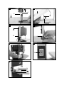
9.5. Adjusting the top saw band guide (5) (Fig. 9)
• Undo locking handle for saw band guide (23).
• Turn the adjustment handle for the saw band guide (22) to
lower the saw band guide (5) as closely as possible (dis-
tance approx. 2-3 mm) over the material to be cut.
• Retighten locking handle (23).
• Check the setting before every cutting process and adjust
if necessary.
9.6. Adjusting the saw table (7) to 90° (Fig. 10+11)
• Set the top saw blade guide (5) fully upwards.
• Undo locking handle (20) and wing nut (31) (Fig. 2).
• Place the angle bracket between the Bandsaw blade (21)
and saw table (7). Angle bracket not included in the scope
of supply.
• Tilt the saw table (7) by turning, until the angle to the
Bandsaw blade (21) is precisely 90°. If the saw table is
already on the screw (49) and a 90° angle cannot be set,
undo the nut (50) and shorten the screw (49) by turning in
a clockwise direction.
• Retighten the locking handle (20) and wing nut (31).
• Also undo the nut (50).
• Adjust the screw (49) sufficiently that the saw table touches
the underside.
• Retighten the nut (50) to fix the screw (49) in position.
9.7. Which saw band to use
The saw band supplied in the band saw is intended for uni-
versal use. The following criteria should be considered when
selecting the saw band:
• It is possible to cut tighter radii with a narrow saw band
than with a wide saw band.
• A wide saw band is used if a straight cut is required. This is
important in particular when cutting wood. The saw band
has a tendency to follow the wood grain and therefore
deviates easily from the desired cutting line.
• Fine-toothed saw bands cut more smoothly, but also more
slowly than coarse saw bands.
Attention: Never use bent or torn saw bands!
9.8. Replacing the saw band (Fig. 1a+1b+14)
• Set the saw band guide (5) at approx. half height between
the saw table (7) and machine frame (15).
• Undo the cover locking mechanisms (10) and open the
side covers (11).
• Remove U-reinforcement (34) as described in 9.1.
• Relieve the Bandsaw blade (21) tension by turning the
clamping screw (1) anti-clockwise.
• Remove the Bandsaw blade (21) from the saw band rollers
(2+8) and through the slot in the saw table (7).
• Place the new Bandsaw blade (21) centrally on both saw
band rollers (2+8). The teeth of the Bandsaw blade (21)
must point downwards in the direction of the saw table
(Fig. 6).
• Tension the Bandsaw blade (21) (see 9.2)
• Close the side cover (11) again.
• Re-install the U-reinforcement (34).
9.9. Replacing the table insert (Fig. 13)
In case of wear or damage, the table insert (6) must be re-
placed; otherwise there is an increased risk of injury.
• Remove the worn table insert (6) by lifting it up and out.
• Installation of the new table insert takes place in reverse
order.
9.10. Extraction nozzle (Fig. 1b)
The band saw is equipped with an extraction nozzle (19) ∅
40 mm for chips.
Only operate the device with a suitable extraction system.
Check and clean the suction channels at regular intervals.
9.11. Push Stick retainer (Fig. 12)
The Push Stick retainer (48) is pre-mounted on the machine
frame. If unused, the Push stick (26) must always be stowed
in the Push Stick retainer.
10. Operation
10.1 On/Off switch (12) (Fig. 15)
• To turn the machine on, press the green button „I“.
• To turn the machine off again, press the red button „0“.
• The band saw is equipped with an undervoltage switch.
With a power failure, the band saw must be switched back
on again.
10.2. Parallel stop (Fig. 16)
• Press the clamping bar (25) of the parallel stop (24) up-
wards
• Slide the parallel stop (24) left or right of the Bandsaw
blade (21) on the saw table (7) and set to the desired
measurement.

GB/IE/NI
8
• Press the clamping bar (25) down to fix the parallel stop
(24) in place. In order to increase the clamping force of
the clamping bar (25), rotate it clockwise until the parallel
stop is sufficiently fixed in place.
• Make sure that the parallel stop (24) always runs parallel
to the Bandsaw blade (21).
10.3. Angled cuts (Fig. 17)
In order to execute angled cuts parallel to the Bandsaw
blade (21), it is possible to tilt the saw bench (7) forwards
from 0° - 45°.
• Undo locking handle (20) and wing nut (31).
• Tilt saw bench (7) forwards, until the desired angle is set
on the degree scale (17).
• Retighten the locking handle (20) and wing nut (31).
• Attention: With a tilted saw table (7), the parallel stop (24)
must always be fitted to the right of the Bandsaw blade
(21) in the working direction. This prevents the workpiece
from slipping.
11. Transport
The machine must only be lifted and transported on its frame
or the frame plate. Never lift the machine at the safety de-
vices, the adjusting levers, or the sawing table.
During the transport the saw blade protection must be in the
lowest position and near the table.
Never raise at the table! Unplug the machine from the mains
during transport.
12. Working instructions
The following recommendations are examples of the safe use
of band saws.
The following safe working methods should be seen as an aid
to safety. They cannot be applied suitably completely or com-
prehensively to every use. They cannot treat every possible
dangerous condition and must be interpreted carefully.
• Connect the machine to a suction unit when working in
closed rooms. A suction device which conforms with commer-
cial regulations must be used for suction in commercial areas.
• Loosen the sawband when the machine is not in operation
(e.g. after finishing work). Attach a notice on the tension of
the saw band to the machine for the next user.
• Collect unused sawbands and store them safely in a dry
place. Check for faults (teeth, cracks) before use. Do not
use faulty sawbands!
• Wear suitable gloves when handling sawbands.
• All protective and safety devices must be securely mounted
on the machine before beginning work.
• Never clean the sawband or the sawband guide with a
hand-held brush or scraper while the sawband is running.
Resin-covered sawbands impair working safety and must
be cleaned regularly.
• For your own protection, wear protective glasses and hear-
ing protection. Wear a hairnet if you have long hair. Roll
up loose sleeves over the elbows.
• Always position the sawband guide as near the workpiece
as possible when working.
• Insure sufficient lighting in the work area and around the
machine.
• Always use the fence for straight cuts to keep the work-
piece from tipping or slipping away.
• When working on narrow workpieces with manual feed,
use the push stick.
• For diagonal cuts, place the saw bench in the appropriate
position and guide the workpiece on the fence.
• In order to cut dovetail tenons and teeth or wedges, bring
the saw table into the corresponding position on the an-
gle scale.
• For arced and irregular cuts, push the workpiece evenly
using both hands with the fingers together. Hold the work-
piece with your hands on a safe area.
• Use a pattern for repeated arced or irregular cuts.
• Insure that the workpiece does not roll when cutting round
pieces.
Attention! After every new setting, we recommend performing
a test cut, in order to check the dimensional settings.
• With all cutting processes, the top saw band guide (5)
must be positioned as close as possible to the workpiece
(see 9.5).
• The workpiece must always be guided with both hands
and kept flat against the saw table (7). This prevents the
Bandsaw blade (21) from jamming.
• Forward feeding should always take place with an even
pressure, which is just sufficient for the saw band to cut
through the material with ease without becoming blocked.
• Always use the parallel stop (24) for all cutting processes
that it can be used for.
• It is better to perform a cut in a single working step than
in multiple steps, which may require that the workpiece be
drawn back. However, if it is not possible to avoid drawing
the workpiece back then the band saw must be switched
off first. Only draw the workpiece back once the Bandsaw
blade (21) has come to a standstill.
• When sawing, the workpiece must always be guided by
its longest side.
• Attention! When processing narrower workpieces it is es-
sential to use a Push stick. The Push stick (26) must always
be stored within reach, on the Push Stick retainer (48) pro-
vided for this purpose on the side of the saw.
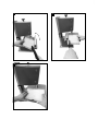
12.1 Performing longitudinal cuts (Fig. 18)
Here, a workpiece is cut in its longitudinal direction.
• Position the longitudinal fence (24) on the left side (if pos-
sible) of the Bandsaw blade (21), in accordance with the
desired width.
• Lower the saw band guide (5) onto the workpiece (9.5).
• Switch on the saw (see 10.1).
• Press one edge of the workpiece against the longitudinal
fence (24) with the right hand, whilst the flat side lies on
the saw bench (7).
• Slide the workpiece at an even feed rate along the longi-
tudinal fence (24) into the Bandsaw blade (21).
• Important: Long workpieces must be secured against tip-
ping at the end of the cutting process (e.g. with reel-off
stand, etc.)
12.2 Performing angled cuts (Fig. 17)
• Set saw bench to desired angle (see „Angled cuts“).
• Perform the cut as described under „Performing longitu-
dinal cuts“.

GB/IE/NI
9
Causes are:
• Drag marks if connection lines are led through window or
door clearances.
• Kinks due to improper attachment or routing of the con-
nection line.
• Cuts caused by running over the connection line.
• Insulation damages caused by pulling the connection line
out of the wall socket.
• Fissures caused by the ageing of the insulation.
Such defective electric connection lines must not be used and
are hazardous due to the insulation damages.
Regularly check the electrical connection lines for damages.
Please make sure that the connection lines are disconnected
from the mains supply during the check.
Electrical connection lines must comply with the relevant VDE
and DIN regulations. Only use connection lines labelled with
H05VV-F.
The labelling of the connection cable with the type specifi-
cation is required.
AC motor
• The mains voltage must be 230 - 240 V~
• Extension cables up to 25 m long must have a cross-section
of 1.5 mm
2
.
Connections and repairs of electrical equipment may only be
carried out by an electrician.
Please provide the following information in the
event of any enquiries:
• Type of current for the motor
• Machine data - type plate
• Machine data - type plate
16. Disposal and recycling
The equipment is supplied in packaging to preven it from be-
ing damaged in transit. The raw materials in this packaging
can be reused or recycled.
The equipment and its accessories are made of various types
of material, such as metal and plastic. Defective components
must be disposed of as special waste. Ask your dealer or
your local council.
When producing angled cuts, only use the parallel stop to
the right of the saw band.
12.3 Freehand cuts (Fig. 19)
One of the most important features of a band saw is the ease
with which it can cut curves and radii.
• Lower the saw band guide (5) onto the workpiece (see
9.5).
• Switch on the saw.
• Press the workpiece firmly onto the saw bench (7) and
slowly slide into the Bandsaw blade (21).
• In many cases it is helpful to roughly saw curves and cor-
ners approximately 6 mm from the line.
• If it is necessary to saw curves that are too tight for the saw
band used, auxiliary cuts must be sawn up to the front face
of the curve, so that these fall off as wood waste when the
final radius is sawn.
13. Cleaning and maintenance
Warning! Prior to any adjustment, maintenance or service
work disconnect the mains power plug!
Cleaning
Keep all safety devices, air vents and the motor housing free
of dirt and dust as far as possible. Wipe the equipment with
a clean cloth or blow it with compressed air at low pressure.
We recommend that you clean the device immediately each
time you have finished using it.
Maintenance
There are no parts inside the equipment which require ad-
ditional maintenance.
14. Storage
Store the device and its accessories in a dark, dry and frost-
proof place that is inaccessible to children. The optimum stor-
age temperature is between 5 and 30˚C.
Store the power tool in original packaging.
Cover the electrical tool in order to protect it from dust and
moisture.
Store the operating manual with the electrical tool.
15. Electrical Connection
The installed electric motor is connected and is ready to work.
The connection complies with the relevant VDE and DIN regu-
lations. The customer-side mains supply and the used exten-
sion line must meet these regulations.
Important information
In the event of an overloading the motor will switch itself
off. After a cool-down period (time varies) the motor can be
switched back on again.
Defective Electric Connection Lines
Often, insulation damages occur on electrical connection
lines.

GB/IE/NI
10
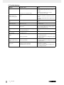
17. Troubleshooting
Problem Possible cause Help
Motor does not work Motor, cable or plug defective, fuses burnt
Housing cover open (limit switch)
Arrange for inspection of the machine by a
specialist. Never repair the motor yourself.
Danger!
Check fuses and replace as necessary
Close housing cover exactly
The motor starts up
slowly and does not
reach operating speed.
Voltage too low, coils damaged, capacitor
burnt
Contact the utility provider to check the voltage.
Arrange for inspection of the motor by a spe-
cialist.
Arrange for replacement of the capacitor by a
specialist
Motor makes excessive
noise
Coils damaged, motor defective Arrange for inspection of the motor by a spe-
cialist
The motor does not
reach its full power.
Circuits in the network are overloaded (lamps
other motors, etc.)
Do not use any other equipment or motors on
the same circuit
Motor overheats easily. Overloading of the motor, insufficient cooling
of the motor
Avoid overloading the motor while cutting,
remove dust from the motor in order to ensure
optimal cooling of the motor
Saw cut is rough or
wavy
Saw blade dull, tooth shape not appropriate
for the material thickness
Resharpen saw blade and/or use suitable saw
blade
Workpiece pulls away
and/or splinters
Excessive cutting pressure and/or saw blade
not suitable for use
Insert suitable saw blade
Saw blade is not running
straight
a) Guide has been wrongly set
b) Wrong saw blade
a) Set the saw blade guide according to the
operating instructions
b) Select a saw blade according to the operat-
ing instructions
Burn marks appear on the
wood during the cutting
work
a) Blunt saw blade
b) Wrong saw blade
a) Change the saw blade
b) Select a saw blade according to the operat-
ing instructions
Saw blade jams during
cutting work
a) Blunt saw blade
b) Deposits on the saw blade
c) Guide has been set poorly
a) Change the saw blade
b) Clean the saw blade
c) Set the saw blade guide according to the
operating instructions

GB/IE/NI
11
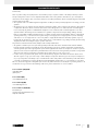
GUARANTEE CERTIFICATE
Dear Customer,
All of our products undergo strict quality checks to ensure that they reach you in perfect condition. In the unlikely event that your device
develops a fault, please contact our service department at the address shown on this guarantee card. Of course, if you would prefer to
call us then we are also happy to offer our assistance under the service number printed below. Please note the following terms under which
guarantee claims can be made:
• These guarantee terms cover additional guarantee rights and do not affect your statutory warranty rights. We do not charge you for this
guarantee.
• Our guarantee only covers problems caused by material or manufacturing defects, and it is restricted to the rectification of these defects
or replacement of the device. Please note that our devices have not been designed for use in commercial, trade or industrial applica-
tions. Consequently, the guarantee is invalidated if the equipment is used in commercial, trade or industrial applications or for other
equivalent activities. The following are also excluded from our guarantee: compensation for transport damage, damage caused by
failure to comply with the installation/assembly instructions or damage caused by unprofessional installation, failure to comply with the
operating instructions (e.g. connection to the wrong mains voltage or current type), misuse or inappropriate use (such as overloading
of the device or use of non-approved tools or accessories), failure to comply with the maintenance and safety regulations, ingress of
foreign bodies into the device (e.g. sand, stones or dust), effects of force or external influences (e.g. damage caused by the device being
dropped) and normal wear resulting from proper operation of the device.
The guarantee is rendered null and void if any attempt is made to tamper with the device.
• The guarantee is valid for a period of 3 years starting from the purchase date of the device. Guarantee claims should be submitted
before the end of the guarantee period within two weeks of the defect being noticed. No guarantee claims will be accepted after the
end of the guarantee period. The original guarantee period remains applicable to the device even if repairs are carried out or parts are
replaced. In such cases, the work performed or parts fitted will not result in an extension of the guarantee period, and no new guarantee
will become active for the work performed or parts fitted. This also applies when an on-site service is used.
• In order to assert your guarantee claim, please send your defective device postage-free to the address shown below. Please enclose
either the original or a copy of your sales receipt or another dated proof of purchase. Please keep your sales receipt in a safe place, as
it is your proof of purchase. It would help us if you could describe the nature of the problem in as much detail as possible. If the defect is
covered by our guarantee then your device will either be repaired immediately and returned to you, or we will send you a new device.
Of course, we are also happy offer a chargeable repair service for any defects which are not covered by the scope of this guarantee or for
units which are no longer covered. To take advantage of this service, please send the device to our service address.
Service-Hotline (GB/IE/NI):
+800 4003 4003
(0,00 €/Min.)
Service-Email (GB):
service.GB@scheppach.com
Service-Email (IE/NI):
service.IE@scheppach.com
Service address (GB/IE/NI):
GreatStar Europe
Unit 55 Romsey Industrial Estate, Romsey
Hampshire SO51 0HR

12
DE/AT/CH
Inhaltsverzeichnis: Seite:
1. Einleitung 13
2. Gerätebeschreibung 13
3. Lieferumfang 13
4. Bestimmungsgemäße Verwendung 14
5. Allgemeine Sicherheitshinweise 14
6. Technische Daten 16
7. Restrisiken 16
8. Vor Inbetriebnahme 17
9. Montage 17
10. Bedienung 19
11. Transport 19
12. Arbeitshinweise 19
13 Reinigung und Wartung 20
14. Lagerung 20
15. Elektrischer Anschluss 20
16. Entsorgung und Wiederverwertung 21
17 Störungsabhilfe 22
18 Garantieurkunde 23
19. Konformitätserklärung 25

13
DE/AT/CH
1. Einleitung
Hersteller:
scheppach
Fabrikation von Holzbearbeitungsmaschinen GmbH
Günzburger Straße 69
D-89335 Ichenhausen
Verehrter Kunde,
Wir wünschen Ihnen viel Freude und Erfolg beim Arbeiten mit
Ihrem neuen Gerät.
Hinweis:
Der Hersteller dieses Gerätes haftet nach dem geltenden Pro-
dukthaftungsgesetz nicht für Schäden, die an diesem Gerät
oder durch dieses Gerät entstehen bei:
• unsachgemäßer Behandlung,
• Nichtbeachtung der Bedienungsanweisung,
• Reparaturen durch Dritte, nicht autorisierte Fach kräfte,
• Einbau und Austausch von nicht originalen Ersatz teilen,
• nicht bestimmungsgemäßer Verwendung,
• Ausfällen der elektrischen Anlage bei Nichtbeachtung der
elektrischen Vorschriften und VDE-Bestimmungen 0100,
DIN 57113 / VDE0113.
Beachten Sie:
Lesen Sie vor der Montage und vor Inbetriebnahme den ge-
samten Text der Bedienungsanleitung durch.
Diese Bedienungsanleitung soll es Ihnen erleichtern, Ihr Elek-
trowerkzeug kennenzulernen und dessen bestimmungsgemä-
ßen Einsatzmöglichkeiten zu nutzen.
Die Bedienungsanleitung enthält wichtige Hinweise, wie Sie
mit dem Elektrowerkzeug sicher, fachgerecht und wirt schaft-
lich arbeiten, und wie Sie Gefahren vermeiden, Reparaturkos-
ten sparen, Ausfallzeiten verringern und die Zuverlässigkeit
und Lebensdauer des Elektrowerkzeugs erhöhen.
Zusätzlich zu den Sicherheitsbestimmungen dieser Bedie-
nungsanleitung müssen Sie unbedingt die für den Be trieb des
Elektrowerkzeugs geltenden Vorschriften Ihres Landes beach-
ten.
Bewahren Sie die Bedienungsanleitung, in einer Plas tik hülle
geschützt vor Schmutz und Feuchtigkeit, bei dem Elektrowerk-
zeug auf. Sie muss von jeder Bedienungsperson vor Aufnah-
me der Arbeit gelesen und sorgfältig beachtet wer den. An
dem Elektrowerkzeug dürfen nur Personen arbeiten, die im
Gebrauch des Elektrowerkzeugs unterwiesen und über die
damit verbundenen Gefahren unterrichtet sind. Das ge for der-
te Mindestalter ist einzuhalten.
Neben den in dieser Bedienungsanleitung enthaltenen
Si cherheitshinweisen und den besonderen Vorschriften
Ih res Landes sind die für den Betrieb von Holzbearbeitungs-
maschinen allgemein anerkannten technischen Regeln zu be-
achten.
Wir übernehmen keine Haftung für Unfälle oder Schäden,
die durch Nichtbeachten dieser Anleitung und den Sicher-
heitshinweisen entstehen.
2. Gerätebeschreibung (Abb. 1-16)
1. Spannschraube
2. Sägebandrolle oben
3. Gummifläche
4. Sägebandschutzeinrichtung
5. Sägebandführung oben
6. Tischeinlage
7. Sägetisch
8. Sägebandrolle unten
9. Standfuß
10. Deckelverriegelung
11. Seitendeckel
12. Ein-/Ausschalter
13. Sicherungsschraube für Sägebandrolle oben
14. Einstellschraube für Sägebandrolle oben
15. Maschinengestell
16. Netzleitung
17. Gradskala für Schwenkbereich
18. Motor
19. Absaugstutzen
20. Feststellgriff für Sägetisch
21. Sägeband
22. Einstellgriff für Sägebandführung
23. Feststellgriff für Sägebandführung
24. Parallelanschlag
25. Spannbügel für Parallelanschlag
26. Schiebestock
27. Inbusschlüssel 3 mm
28. Inbusschlüssel 4 mm
29. Schraubenzieher
30. Gabelschlüssel
31. Flügelmutter
32. Klemmplatte
33. Rändelmutter
34. U-Versteifung
35. Inbusschraube für Stützlager oben
36. Stützlager oben
37. Führungsstift, oben
38. Inbusschraube für Führungsstifte oben
39. Aufnahmehalter (oben)
40. Inbusschraube Aufnahmehalter oben (2x)
41. Inbusschraube Stützlager unten
42. Stützlager unten
43. Schraube Aufnahmehalter unten
44. Sägebandschutz
45. Inbusschraube für Führungsstifte unten
46. Führungsstift, unten
47. Aufnahmehalter (unten)
48. Schiebestockhalterung
49. Schraube (Sägetischjustierung)
50. Mutter (Sägetischjustierung)
51. Inbusschlüssel 5 mm
3. Lieferumfang
• Öffnen Sie die Verpackung und nehmen Sie das Gerät
vorsichtig heraus.
• Entfernen Sie das Verpackungsmaterial sowie Verpa-
ckungs-/ und Transportsicherungen (falls vorhanden).
• Überprüfen Sie, ob der Lieferumfang vollständig ist.
Seite wird geladen ...
Seite wird geladen ...
Seite wird geladen ...
Seite wird geladen ...
Seite wird geladen ...
Seite wird geladen ...
Seite wird geladen ...
Seite wird geladen ...
Seite wird geladen ...
Seite wird geladen ...
Seite wird geladen ...
Seite wird geladen ...
Seite wird geladen ...
Seite wird geladen ...
Seite wird geladen ...
Seite wird geladen ...
-
 1
1
-
 2
2
-
 3
3
-
 4
4
-
 5
5
-
 6
6
-
 7
7
-
 8
8
-
 9
9
-
 10
10
-
 11
11
-
 12
12
-
 13
13
-
 14
14
-
 15
15
-
 16
16
-
 17
17
-
 18
18
-
 19
19
-
 20
20
-
 21
21
-
 22
22
-
 23
23
-
 24
24
-
 25
25
-
 26
26
-
 27
27
-
 28
28
-
 29
29
-
 30
30
-
 31
31
-
 32
32
-
 33
33
-
 34
34
-
 35
35
-
 36
36


Parkside PBS 350 A1 Operating And Safety Instructions Manual
- Typ
- Operating And Safety Instructions Manual
in anderen Sprachen
- English: Parkside PBS 350 A1
Verwandte Artikel
Andere Dokumente
-
Scheppach HBS261 Benutzerhandbuch
-
-
EINHELL TC-SB 305 U Benutzerhandbuch
-
-
-
-
-
-
Powermatic PM1500 Operating Instructions Manual
-