Powermatic PM1500 Operating Instructions Manual
- Typ
- Operating Instructions Manual

PM1500
WOOD BAND SAW
HOLZ-BANDSÄGE
SCIE A RUBAN A BOIS
Original:
GB
Operating Instructions
Translations:
D
Gebrauchsanleitung
F
Mode d´emploi
JPW (Tool) AG
Tämperlistrasse 5
CH-8117 Fällanden
Switzerland
Phone +41 44 806 47 48
Fax +41 44 806 47 58
www.powermatic.com
M- 791500MP, 1791500TP 2016-10

CE-Conformity Declaration
CE-Konformitätserklärung
Déclaration de Conformité CE
Product / Produkt / Produit:
Band saw / Bandsäge / Scie à ruban
PM 1500
(791500MP, 1791500TP)
Brand / Marke / Marque:
POWERMATIC
Manufacturer / Hersteller / Fabricant:
JPW (Tool) AG, Tämperlistrasse 5, CH-8117 Fällanden
Schweiz / Suisse / Switzerland
We hereby declare that this product complies with the regulations
Wir erklären hiermit, dass dieses Produkt der folgenden Richtlinie entspricht
Par la présente, nous déclarons que ce produit correspond aux directives suivantes
2006/42/EC
Machinery Directive / Maschinenrichtlinie / Directive Machines
2014/30/EU
electromagnetic compatibility / elektromagnetische Verträglichkeit / compatibilité électromagnétique
designed in consideration of the standards
und entspechend folgender zusätzlicher Normen entwickelt wurde
et été développé dans le respect des normes complémentaires suivantes
EN ISO 12100:2010, EN 60204-1:2006+AC:2010, EN 1807-1:2013
EC type examination performed by / EG-Baumusterprüfung durchgeführt von / examen CE de type par
UDEM International Certification Auditing Training Centre Industry and Trade Co. Ltd.,
Mutlukent Mahallesi 2073 Sokak No:10 Cankaya - Ankara - Turkey (notified body No: 2292)
certificate number / Zertifikat Nummer/ numéro de certificat
M.2016.103.6984
Responsible for the Documentation / Dokumentations-Verantwortung / Résponsabilité de Documentation:
Hansjörg Meier
Head Product-Mgmt. / Leiter Produkt-Mgmt. / Resp. Gestion des Produits
JPW (Tool) AG
2016-10-24 Alain Schmid, General Manager
JPW (Tool) AG, Tämperlistrasse 5, CH-8117 Fällanden
Schweiz / Suisse / Switzerland

2
GB - ENGLISH
Operating Instructions
Dear Customer,
Many thanks for the confidence you have shown in us with the purchase of your new POWERMATIC-machine. This manual has been prepared
for the owner and operators of a POWERMATIC PM1500 band saw to promote safety during installation, operation and maintenance
procedures. Please read and understand the information contained in these operating instructions and the accompanying documents. To
obtain maximum life and efficiency from your machine, and to use the machine safely, read this manual thoroughly and follow instructions
carefully.
…Table of Contents
1. Declaration of conformity
2. POWERMATIC Warranty
3. Safety
Authorized use
General safety notes
Remaining hazards
4. Machine specifications
Machine description
Technical data
Noise emission
Dust emission
Contents of delivery
5. Transport and start up
Transport and installation
Assembly
Mains connection
Dust connection
Starting operation
6. Machine operation
7. Setup and adjustments
Saw blade selection
Changing the saw blade
Blade tracking adjustment
Blade tension adjustment
Blade guide adjustment
Folding the bandsaw blade
8. Maintenance and inspection
9. Troubleshooting
10. Environmental protection
11. Available accessories
12. „Safe operation” ................ appendix A
1. Declaration of conformity
On our own responsibility we hereby declare that this product
complies with the regulations* listed on page 2. Designed in
consideration with the standards**. CE type examination***
performed by****.
2. POWERMATIC Group Warranty
The POWERMATIC Group makes every effort to assure that its
products meet high quality and durability standards and warrants
to the original retail consumer/purchaser of our products that
each product be free from defects in materials and workmanship
as follows:
2 YEAR LIMITED WARRANTY ON ALL PRODUCTS UNLESS SPECIFIED
OTHERWISE.
This Warranty does not apply to defects due to directly or
indirectly misuse, abuse, negligence or accidents, normal wear-
and-tear, repair or alterations outside our facilities, or to a lack of
maintenance.
The POWERMATIC group limits all implied warranties to the period
specified above, from the date the product was purchased at
retail.
To take advantage of this warranty, the product or part must be
returned for examination, postage prepaid, to an authorized repair
station designated by our office.
Proof of purchase date and an explanation of the complaint must
accompany the merchandise.
If our inspection discloses a defect, we will either repair or replace
the product, or refund the purchase price if we cannot readily and
quickly provide a repair or replacement, if you are willing to accept
a refund.
We will return repaired product or replacement at POWERMATIC’S
expense, but if it is determined there is no defect, or that the
defect resulted from causes not within the scope of
POWERMATIC’S warranty, then the user must bear the cost of
storing and returning the product.
The POWERMATIC Group reserves the right to make alterations to
parts, fittings, and accessory equipment which they may deem
necessary for any reason whatsoever.
3. Safety
3.1 Authorized use
This machine is designed for sawing wood, wood derived materials
as well as similar to be machined hard plastics only.
Machining of other materials is not permitted and may be carried
out in specific cases only after consulting with the manufacturer.
No metal workpieces may be machined.
The workpiece must allow to safely be loaded, supported and
guided.

The proper use also includes compliance with the operating and
maintenance instructions given in this manual.
The machine must be operated only by persons familiar with its
operation, maintenance and repair and who are familiar with its
hazards.
The required minimum age must be observed
The machine must only be used in a technically perfect condition.
When working on the machine, all safety mechanisms and covers
must be mounted.
In addition to the safety requirements contained in this operating
instructions and your country’s applicable regulations, you should
observe the generally recognized technical rules concerning the
operation of woodworking machines.
Any other use exceeds authorization.
In the event of unauthorized use of the machine, the manufacturer
renounces all liability and the responsibility is transferred
exclusively to the operator.
3.2 General safety notes
Woodworking machines can be dangerous if not used properly.
Therefore the appropriate general technical rules as well as the
following notes must be observed.
Read and understand the entire instruction manual before
attempting assembly or operation.
Keep this operating instruction close by the machine, protected
from dirt and humidity, and pass it over to the new owner if you
part with the tool.
No changes to the machine may be made.
Daily inspect the function and existence of the safety appliances
before you start the machine.
Do not attempt operation in this case, protect the machine by
unplugging the mains cord.
Before operating the machine, remove tie, rings, watches, other
jewellery, and roll up sleeves above the elbows.
Remove all loose clothing and confine long hair.
Wear safety shoes; never wear leisure shoes or sandals.
Always wear the approved working outfit
- safety goggles
- ear protection
- dust protection
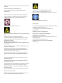
Do not wear gloves while operating this machine.
Wear work gloves for the safe handling of sawblades.
Observe the chapter “save operation” in this manual.
Control the stopping time of the machine, it may not be longer
than 10 seconds.
Work only with a sharp and flawless sawblade.
Work only with fence well tightened.
Insure that the workpiece does not roll when cutting round pieces.
Use suitable table extensions and supporting aids for difficult to
handle workpieces.
Always lower the blade guide close to the workpiece.
With the machine table is inclined use the fence and position it on
the bottom side only.
Always hold and guide the workpieces safely during machining.
Remove cut and jammed workpieces only when motor is turned
off and the machine is at a complete standstill.
Install the machine so that there is sufficient space for safe
operation and workpiece handling.
Keep work area well lighted.
The machine is designed to operate in closed rooms and must be
placed stable on firm and levelled ground.
Make sure that the power cord does not impede work and cause
people to trip.
Keep the floor around the machine clean and free of scrap
material, oil and grease.
Stay alert!
Give your work undivided attention.
Use common sense.
Keep an ergonomic body position.
Maintain a balanced stance at all times.
Do not operate the machine when you are tired.
Do not operate the machine under the influence of drugs, alcohol
or any medication. Be aware that medication can change your
behaviour.
Never reach into the machine while it is operating or running
down.

Keep children and visitors a safe distance from the work area.
Never leave a running machine unattended. Before you leave the
workplace switch off the machine.
Do not operate the electric tool near inflammable liquids or gases.
Observe the fire fighting and fire alert options, for example the fire
extinguisher operation and place.
Do not use the machine in a dump environment and do not expose
it to rain.
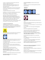
Wood dust is explosive and can also represent a risk to health.
Dust form some tropical woods in particular, and from hardwoods
like beach and oak, is classified as a carcinogenic substance.
Always use a suitable dust extraction device
Before machining, remove any nails and other foreign bodies from
the workpiece.
Use a push block when working the ends of narrow stock.
Always store the push stick or the push wood handle with the
machine, also when not in use.
Specifications regarding the maximum or minimum size of the
workpiece must be observed.
Do not remove chips and workpiece parts until the machine is at a
complete standstill.
Never operate with the guards not in place – serious risk of injury!
Do not stand on the machine.
Connection and repair work on the electrical installation may be
carried out by a qualified electrician only.
Have a damaged or worn cord replaced immediately.
Make all machine adjustments or maintenance with the machine
unplugged from the power source.
Remove defective sawblades immediately.
3.3 Remaining hazards
When using the machine according to regulations some remaining
hazards may still exist
The moving sawblade in the work area can cause injury.
Broken saw blades can cause injuries.
Thrown workpieces can lead to injury
Wood chips and sawdust can be health hazards. Be sure to wear
personal protection gear such as safety goggles ear- and dust
protection.
Use a suitable dust exhaust system.
The use of incorrect mains supply or a damaged power cord can
lead to injuries caused by electricity.
4. Machine specifications
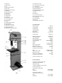
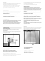
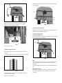
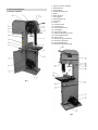
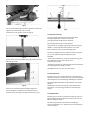
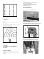
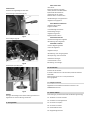
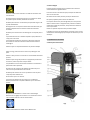
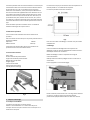
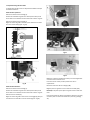
4.1 Machine Description
Fig 1

1…Lifting ring
2…Upper wheel
3…Tire
4…Blade tracking window
5…Door catch
6…Height adjust hand wheel
7…Guide post
8…Upper blade guides
9…Table insert
10…Wheel brush
12…Lower wheel
13…Drive belt
14….Lower wheel cover
15…Fence support rail
16…Fence carrier
17….Fence
18…On/Off magnetic switch
20…Warning label
21…Blade tension window
22…Blade tension indicator
23…Upper wheel cover
24…Blade tension interlock switch
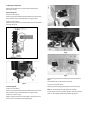
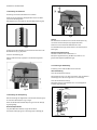
Fig 2
25…Blade tension lever
26…Tension lever position label
27…Tracking knob
28…Tracking knob lock lever
29…Machine ID-label
30…Blade tension hand wheel
31…Motor lift handle
32…Motor
33…Dust port
34…Trunnion lock handle
35…Trunnion fine adjust knob
36…Resaw guide
37…Cast iron table
38…Mitre slot
39…Guide post locking knob
4.2 Technical data
Wheel diameter 381 mm
Cutting width max 368 mm
Cutting height max 355 mm
Sawblade length 3886 mm
Blade width 3 - 25 mm
Blade thickness 0,5 – 0,7 mm
Cutting speed 950 m/min
Machine Table(Lx W) 545x405 mm
Table tilting range -10° to 45°
Working height 1015mm
Dust port diameter (2x) 100mm
Overall (LxWxH) 770x870x2040mm
Weight 179 kg
Mains 1~230V, PE, 50Hz
Motor output power 2.2 kW (3HP) S1
Reference current 12 A
Extension cord (H07RN-F): 3x1,5mm²
Installation fuse protection 16A
Mains 3~400V, PE, 50Hz
Motor output power 2.2 kW (3 HP) S1
Reference current 4.8 A
Extension cord (H07RN-F): 5x1,5mm²
Installation fuse protection 16A
Insulation protection class I
4.3 Noise emission
Determined according to EN 1807
(Inspection tolerance 4 dB)
Workpiece beech:
T=30mm, L=1500mm, moisture 8,5%
Acoustic power level
(according to EN ISO 3746):
Idling LwA 82 dB(A)
Operating LwA 93 dB(A)
Acoustic pressure level
(according to EN ISO 11202):
Idling LpA 74 dB(A)
Operating LpA 87 dB(A)

The specified values are emission levels and are not necessarily to
be seen as safe operating levels. Although there is a correlation
between emission and imission levels, these do not constitute a
basis for determining the necessity of additional safety measures.
Workplace conditions which could influence the noise imission
level include the duration of resonance, spatial particulars, other
noise sources etc. For example, the number of machines and other
work being performed. The permissible workplace levels can vary
from country to country.
This information is intended to allow the user to make a better
estimation of the hazards and risks involved.
4.4 Dust emission
The band saw has been dust emission inspected.
At an air velocity of 20 m/s on the dust port dia 100mm:
Vacuum pressure 1250 Pa
Volume flow 565 m³/h
The machine meets a workplace dust emission of 2 mg/m³.
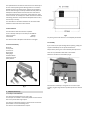
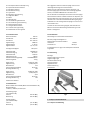
4.5 Content of delivery
Band saw
Fence profile
Fence carrier
Resaw guide
Mitre gauge
Saw blade 10mm
Operating manual
Spare parts list
Fig 3
5. Transport and start up
5.1 Transport and installation
The machine will be delivered on an open crate.
For transport use a forklift or hand trolley. Make sure the machine
does not tip or fall off during transport.
The machine is designed to operate in closed rooms and must be
placed stable on firm and levelled ground.
The machine can be bolted down if required.
Fig 4
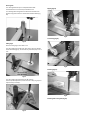
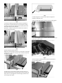
For packing reasons the machine is not completely assembled.
5.2 Assembly
If you notice any transport damage while unpacking, notify your
supplier immediately. Do not operate the machine!
Dispose of the packing in an environmentally friendly manner.
Clean all rust protected surfaces with a mild solvent.
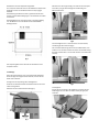
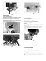
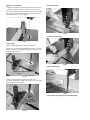
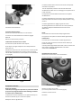
Attach the handle to the hand wheel ( Fig 5)
Fig 5
Place the fence assembly on the guide rail and use the nylon
screws (C, Fig 6) to align the fence profile square to the machine
table.

Fig 6
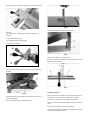
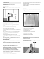
The fence profile can be installed in two positions, vertically (Fig 6)
or horizontally (Fig 7).
Horizontal position is useful for smaller workpieces, for narrow
shallow cuts.
(Note: The scale cannot be used with horizontal fence).
Fig 7
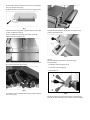
Fence scale:
Move the fence assembly flush to the sawblade and set the
pointer to zero. If cursor is not at zero, loosen two screws (D, Fig 8)
to adjust.
Fig 8
Check the clearance between the table and the fence. The fence
should not rub on the table surface but be slightly above (Fig 9).
Use the nylon screws (C, Fig 6) to adjust.
Fig 9
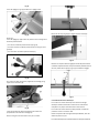
The table has been aligned at the factory, so that the mitre slot is
parallel to the saw blade.
Use a long ruler against the saw blade body to inspect (Fig 10).
If mitre slot is not parallel, loosen the four screws (E, Fig 11) to
adjust the table
Fig 11
Make sure the fence is parallel to the miter slot (Fig12)
Fig 12

The back adjustment screws (F, Fig 13) allow a precise adjustment.
Fig 13
Info Note:
The back adjustment screws (F) also adjust the fence locking
positions.
- to take fence off (A, Fig 14)
- to slide fence along the guide rail (B)
- to lock fence in place (C)
Fig 14
To tilt the table, loosen the lock handle (A, Fig 14) and rotate the
knob (B).
Fig 14
The 90° table stop must be adjusted, so that the table is square to
the sawblade (Fig 15).
Place a square against the saw blade to inspect.
Fig 15
Loosen nut (D, Fig 16) to adjust the stop bolt (C).
Fig 16
Make a final inspection on the fence setup.
If the fence is not exactly parallel to the saw blade, use the nylon
screws (C, Fig 17) to adjust.
Fig 17
5.3 Mains connection
Mains connection and any extension cords and plugs used must
comply with the information on the machine licence plate.
The mains connection must have a 16A surge-proof fuse.
Only use extension cords marked H07RN-F, with wires 1,5mm
2
or
more.
Power cords and plugs must be free from defects.
Connections and repairs to the electrical equipment may only be
carried out by qualified electricians.

ATTENTION:
-Check first if the saw blade is tensioned and runs freely and if all
safety devices are fitted before starting the machine.
- If the direction of rotation is not correct, the phase converter
inside the CEE Euro plug must be pushed in and turned 180°.
(The saw blade must run down to the table)
5.4 Dust connection
Before initial operation, the machine must be connected to a dust
extractor. The suction should switch on automatically when the
bandsaw is switched on.
The flow rate on the suction port must be 20m/sec.
Flexible hoses must be of non-flammable quality, and must be
connected to the machine ground system.
5.5 Starting operation
You can start the machine with the green ON-button. The red OFF-
button on the main switch (18, Fig 1) stops the machine.
In case of machine overload the motor overload cut-off will react.
After appr.10 min of cooling the machine can be started again.
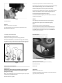
6. Machine operation
Correct working position:
In front of the machine standing in the direction of cutting.
Cut preparation:
Bring the upper blade guide to a distance of approximately 3mm
to the workpiece (Fig 18).
Fig 18
For your own safety, always set the saw guide as close to the
workpiece as possible.
Work only with a sharp and flawless sawblade.
Make sure blade is tracked and tensioned correctly.
Make sure blade guides are adjusted correctly.
If using the fence, move it into position and lock it to the guide rail.
Work only with rip fence securely locked in place.
For narrow shallow cuts on the rip fence, place the fence profile
into the horizontal position (Fig 7).
Turn on band saw and allow it to reach full speed.
Workpiece handling:
Hands placed flat on the workpiece outside the cutting area.
Feed the workpiece towards the saw blade in the direction of the
saw line, and cut as required by turning to follow the line drawn.
Push the workpiece steadily forward; complete the cut as a single
movement.
If possible, do not draw the workpiece back, as this could cause
the sawblade to run off its wheels.
Support long and wide workpieces with helping roller stands.
Near the cutting area use a push stick to feed, to prevent your
hands to come close to the saw blade.
Make relief cuts whenever necessary. A relieve cut is an extra cut
made through the waste portion of the wood.
Use a feeding template to safely guide small and narrow
workpieces.
Use a suitable wedge to prevent round timber from turning under
the pressure of the cut.
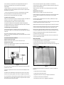
Blade Drift:
Blade drift is a frequent problem on rip cuts and during resawing.
Blade drift may occur when the fence is being used, the blade
begins to wander off the cutting line (Fig 19).
.
Fig 19
Blade drift can be caused by a number of factors.
- The saw blade follows the grain
- The saw blade is dull.
- Blade guides not adjusted correctly.
- Blade tension insufficient.
- Blade-teeth have asymmetric“set”

Resaw guide:
The resaw guide allows you to compensate blade drift.
The feed direction can be lined up to follow the cut.
For resawing attach the guide to the fence with the lock knob.
Position the guide so that it is centred with the blade teeth. (Fig
20).
Fig 20
Mitre gauge:
Place the mitre gauge in the table T-slot.
The mitre gauge bar has two slots, each with a set screw. Rotate
these set screws (Fig 21), to eliminate any unwanted play in the T-
slot.
Fig 21
The mitre gauge has positive stops for 90° and 45°:
If the stops need adjustment, loosen the lock nuts (D, Fig 22) and
adjust the stop screws (E).
Fig 22
Ripping (Fig 23)
Fig 23
Crosscutting (Fig 24)
Fig 24
Resawing (Fig 25)
Fig 25
Resawing with resaw guide (Fig 26)

Fig 26
For the authorized use of the machine observe the appendix A
“safe operation“
(on the last pages of this operating manual)
A.1: Performing high cuts
A.2.: Performing diagonal cuts
A.3.: Tenon cutting
A.4.: Cutting of wedges
A.5.: Curved cuts
A.6.: Arc cuts
A.7.: Cutting with template
A.8.: Circular cutting
A8.1 Set up without workpiece
A8.2 Placing the workpiece
A8.3 Machining
7. Setup and adjustments
General note:
Setup and adjustment work may only be carried out after the
machine is protected against accidental starting by pulling the
mains plug.
7.1 Saw blade selection
The sawblade has to meet the technical specification.
Choose a suitable sawblade, according to the cutting operation
and according to the material to be cut.
For a high rip cut:
- use a wide sawblade, coarse teethed
(e.g. 20mm, 3 T/”)
For a narrow curved cut:
- use a narrow sawblade
(e.g. 3mm, 14 T/”).
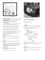
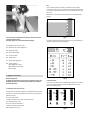
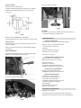
Pitch:
The pitch should not be smaller than necessary, as the feed speed
is reduced if there are too many teeth working on the workpiece
simultaneously, which causes the saw blade to wear more quickly.
Ideally, 3 to 12 teeth should be in action at the same time (Fig 27).
Fig 27
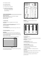
The following table shows recommended saw blade pitch in
relation to workpiece thickness (Fig 28).
Fig 28
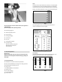
Tooth Shape:
The tooth shape effects the chip capacity and the feed rate. The
following table shows common tooth shapes (Fig 29):
Fig 29

A- Regular tooth:
The most common used tooth shape. 0° rake angle.
Suited for cut-off and contour sawing of most materials. For
cutting materials where a fine cut is required.
B- Skip tooth:
Widely spaced teeth, to prevent clogging. 0°rake angle.
For resawing and ripping thick stock, especially soft woods.
C- Hooked tooth:
Large teeth and a positive rake angle, for aggressive, faster cutting.
For resawing and ripping thick stock, especially hard woods.
D- Variable tooth:
Variable tooth shape and spacing produces smooth cuts and
dampens vibrations.
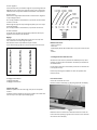
Set:
Saw teeth are bent out of the plane of the saw body, resulting in a
wide cut in the workpiece.
This helps reduce friction and allows curve cuts).
The alternate set (Y, Fig 30) is the most used for woodworking
blades.
Fig 30
X- Raker set
Y- Alternate set
Z- Wavy set
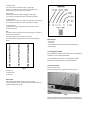
Blade width:
Use a possibly wide blade, except for contour cutting.
The following table shows relation between saw blade width and
smallest cutting radius (Fig 31).
Fig 31
Blade material:
- carbon steel
- alloy steel
- bimetal (HSS teeth welded onto alloy steel blade body)
-carbide tipped.
7.2 Changing the sawblade
Check sawblade for flaws (cracks, broken teeth, bending) before
installation. Do not use faulty sawblades.
The sawblade teeth must point in cutting direction (down)
Always wear suitable gloves when handling sawblades.
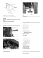
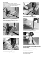
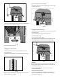
To remove the blade:
Open the wheel covers.
Remove the table insert (F, Fig 32) and the table pin (G).
Fig 32
Release the blade tension by operating the quick blade tension
lever (Q, Fig 33) and by turning the blade tension handwheel (A).

Fig 33
After the new saw blade is installed, tighten the sawblade
sufficiently. Follow the scale (B, Fig 34).
Fig 34
Close the wheel covers.
7.3 Blade tracking adjustment
Blade tracking shall never be performed when the machine is
running.
The sawblade must run on the centre of the rubber tyres (Fig 35).
Fig 35
Lower the guide post until you can see the blade through the
tracking window (C, Fig 36).
Loosen the lock handle (D)
With the knob (E) on the back of the machine the blade tracking
can be adjusted.
Fig 36
7.4 Blade tension adjustment
Blade tension is set with the blade tension handwheel (A, Fig 37).
Tighten the placed sawblade sufficiently.
Follow the scale (B, Fig 34).
Quick blade tension lever :
To operate the machine, place the quick blade tension lever (Q, Fig
37) in the Full-Tension position (X).
Fig 37
Note:
When the band saw is not in use, place the quick blade tension
lever to the Partial-Tension position (Y), this will prolong the
blade’s life.
For blade changing, place the lever to the Fully-Released position
(Z).
Blade tension sensor:
The machine is equipped with an interlock switch. The machine
can only be operated when the saw blade is tensioned (lever
position X).

7.5 Blade guide adjustment
Blade guide adjustment shall never be performed when the
machine is running.
Upper blade guide:
Loosen the lock knob (F).
Position the guide assembly forward/ backward so that the teeth
keep a distance of approximately 2mm to the guide rollers.
Loosen the lock knob (I).
Adjust the back guide roller so that the distance to the saw blade is
1mm (Fig 38~Fig 39).
Fig 38
Fig 39
Lower blade guide:
Loosen the lock knob (L).
Position the guide assembly forward/ backward so that the teeth
keep a distance of approximately 2mm to the guide rollers.
Loosen the knurled nut (O).
Adjust the back guide roller with the adjust screw (P) so that the
distance to the saw blade is 1mm (Fig 40~Fig 42).
Fig 40
Fig 41
Fig 42
Set the lateral guide rollers so that they contact the sawblade
lightly.
The sawblade may not be pushed out of place.
Loosen the lock knobs (G, M).
Adjust the guide bearing by rotating the knurled knob (H, N).
Note: do not fore guide bearings against side of blade.
A quick way to achieve the spacing needed (~0.1mm) is placing a
paper or note between blade and guide bearing (Fig 43).

Fig 43
Lock all fasteners.
Test run:
Make sure all fasteners are locked.
Turn the wheels by hand and inspect the adjustments made.
Start the machine with care.
7.6 Folding the bandsaw blade
A folded saw blade needs less space.
Always wear suitable gloves when handling sawblades.
Hold the bandsaw blade in one hand. Let it hang down vertically
and hold it to the floor with a foot. Turn your hand through 360°, a
complete circle, as you move it down towards the floor (Fig 44).
Fig 44
8. Maintenance and inspection
General notes:
Maintenance, cleaning and repair work may only be carried out
after the machine is protected against accidental starting by
pulling the mains plug.
Repair and maintenance work on the electrical system may only be
carried out by a qualified electrician.
Clean the machine regularly.
Inspect the proper function of the dust extraction daily.
All protective and safety devices must be re-attached immediately
after completed cleaning, repair and maintenance work.
Defective safety devices must be replaced immediately.
Inspect the correct blade tension regularly. Take away the blade
tension if the machine is not in use for a longer time period.
Inspect the blade guide adjustment regularly.
Check bandsaw blades regularly for faults. Replace a defective
sawblades immediately.
Wheels:
The rubber tyre of the wheels must be cleaned regularly.
The upper wheel support must be lubricated regularly.
Drive:
The belt tension must be inspected regularly.
The motor brake works electro-mechanically (brake motor).
If braking time should exceed 10 seconds, the motor brake
assembly needs to be replaced. Contact your POWERMATIC
service station immediately.
Belt replacement:
Disconnect machine from power source.
Remove the bolt and washer (F, Fig 45).
Fig 45
Remove the bandsaw wheel.
(you may need to use a pulley puller to remove it).
Install the new belt.
Reassemble.
Table insert:
Replace a worn table insert.
The table insert (Fig 46) must be made out of cut-able material
(e.g. wood, plastic, aluminium)

Fig 46
POWERMATIC part number: PM1500-045
The table insert may not project above table surface.
Saw blades:
The servicing of sawblades should only be performed by a trained
person.
Only use sharp and properly set sawblades.
Lubrication points:
Periodically apply a light all-purpose grease to rack and pinion (Fig
47)
Fig 47
To the table trunnions (Fig 48).
Fig 48
To the blade tension screw.
Fig 49
Note:
Bearings on the band saw are pre lubricated and sealed and do not
require attention.
9. Trouble shooting
Motor doesn’t start
*No electricity-
check mains and fuse.
*Defective switch, motor or cord-
consult an electrician.
*Overload has reacted-
Wait and start again.
*Wheel covers not closed-
*Saw blade not tensioned-
Machine vibrates excessively
*Stand on uneven floor-
adjust stand for even support.
*dust on wheel-
clean tires.
*sawblade has cracks-
replace sawblade immediately
Cut is not square
*Table stop setting wrong.
*Blade guide setting is bad
Cutting surfaces is bad
*Wrong sawblade used
*resin collection on sawblade
*sawblade is dull
*Blade guide setting is bad
*Blade tension too low
*workpiece inhomogeneous
*Feed pressure too high-
Do not force the workpiece.
10. Environmental protection
Protect the environment.

Your appliance contains valuable materials which can be recovered
or recycled. Please leave it at a specialized institution.
11. Available accessories
Refer to the POWERMATIC Pricelist
for various saw blades.
12. Safe operation
See appendix A (on the last pages of this operating manual)
A.1: Performing high cuts
A.2.: Performing diagonal cuts
A.3.: Tenon cutting
A.4.: Cutting of wedges
A.5.: Curved cuts
A.6.: Arc cuts
A.7.: Cutting with template
A.8.: Circular cutting
A8.1 Set up without workpiece
A8.2 Placing the workpiece
A8.3 Machining

DE - DEUTSCH
Gebrauchsanleitung
Sehr geehrter Kunde,
vielen Dank für das Vertrauen, welches Sie uns beim Kauf Ihrer neuen POWERMATIC-Maschine entgegengebracht haben. Diese Anleitung ist
für den Inhaber und die Bediener zum Zweck einer sicheren Inbetriebnahme, Bedienung und Wartung der
Bandsäge POWERMATIC PM1500 erstellt worden. Beachten Sie bitte die Informationen dieser Gebrauchsanleitung und der beiliegenden
Dokumente. Lesen Sie diese Anleitung vollständig, insbesondere die Sicherheitshinweise, bevor Sie die Maschine zusammenbauen, in Betrieb
nehmen oder warten. Um eine maximale Lebensdauer und Leistungsfähigkeit Ihrer Maschinen zu erreichen befolgen Sie bitte sorgfältig die
Anweisungen.
…Inhaltsangabe
1. Konformitätserklärung
2. POWERMATIC Garantieleistungen
3. Sicherheit
Bestimmungsgemäße Verwendung
Allgemeine Sicherheitshinweise
Restrisiken
4. Maschinenspezifikation
Maschinen Überblick
Technische Daten
Schallemission
Staubemmission
Lieferumfang
5. Transport und Inbetriebnahme
Transport und Aufstellung
Montage
Elektrischer Anschluss
Absaug Anschluss
Inbetriebnahme
6. Betrieb der Maschine
7. Rüst- und Einstellarbeiten
Sägebandwahl
Montage des Sägebandes
Einstellung des Bandlaufes
Einstellung der Bandspannung
Einstellung der Bandführung
Zusammenlegen des Bandes
8. Wartung und Inspektion
9. Störungsabhilfe
10. Umweltschutz
11. Lieferbares Zubehör
12. „sicheres Arbeiten“ .............. Anhang A
1. Konformitätserklärung
Wir erklären in alleiniger Verantwortlichkeit, dass dieses Produkt
mit den auf Seite 2 angegebenen Richtlinien* übereinstimmt. Bei
der Konstruktion wurden folgende Normen** berücksichtigt und
eine EG-Baumusterprüfung *** von **** durchgeführt.
2. POWERMATIC Garantieleistungen
Die POWERMATIC -Gruppe ist bemüht dass seine Produkte die
hohen Kundenerwartungen an Qualität und Haltbarkeit erfüllen.
POWERMATIC garantiert an den Erstbesitzer dass jedes Produkt
frei von
Material- und Verarbeitungsdefekten ist wie folgt:
2 JÄHRIGE POWERMATIC-GARANTIE AUF ALLE PRODUKTE SOWEIT
NICHT ANDERS ANGEGEBEN.
Diese Garantie trifft nicht auf jene Defekte zu, welche auf direkten
oder indirekten Missbrauch, Unachtsamkeit, Unfallschaden,
unsachgemäße Reparatur, mangelhafte Wartung sowie normalen
Verschleiß zurückzuführen sind.
Die POWERMATIC-Garantie beginnt mit dem Verkaufsdatum an
den Erstkunden.
Um die verlängerte POWERMATIC-Garantie in Anspruch zu
nehmen, muss das fehlerhafte Produkt oder Teil zu einem
autorisierten POWERMATIC-Händler zur Überprüfung
zurückgebracht werden.
Ein Beweismittel des Erwerbsdatums und eine Erklärung der
Beanstandung muss der Waren beigefügt werden.
Falls unsere Kontrolle einen Defekt feststellt reparieren wir diesen
oder ersetzen das Produkt. Sollten wir nicht in angemessener Zeit
eine Reparatur oder einen Ersatz zur Verfügung stellen können,
erstatten wir den Kaufpreis zurück.
POWERMATIC retourniert das reparierte Produkt oder dessen
Ersatz kostenlos. Sollte jedoch festgestellt werden, dass es sich um
keinen Defekt handelt oder dass dessen Ursachen nicht innerhalb
der POWERMATIC-Garantie liegen, muss der Kunde die Kosten der
Lagerung und des Retourversands selbst tragen.
POWERMATIC reserviert sich das Recht
Änderungen an Teilen und Zubehören vorzunehmen falls dies für
nötig erachtet wird.
3. Sicherheit
3.1 Bestimmungsgemäße Verwendung
Die Maschine ist geeignet zum Sägen von Holz und
Holzersatzstoffen, sowie diesen ähnlich zu bearbeitende harte
Kunststoffe.
Die Bearbeitung anderer Werkstoffe ist nicht zulässig bzw. darf in
Sonderfällen nur nach Rücksprache mit dem Maschinenhersteller
erfolgen.
Es dürfen keine metallischen Werkstoffe bearbeitet werden.

Es dürfen nur Werkstücke bearbeitet werden welche sicher
aufgelegt und geführt werden können.
Die bestimmungsgemäße Verwendung beinhaltet auch die
Einhaltung der vom Hersteller angegebenen Betriebs- und
Wartungsanweisungen.
Die Maschine darf ausschließlich von Personen bedient werden,
die mit Betrieb und Wartung vertraut und über die Gefahren
unterrichtet sind.
Das gesetzliche Mindestalter ist einzuhalten.
Die Maschine nur in technisch einwandfreiem Zustand benutzen.
Beim Arbeiten an der Maschine müssen sämtliche
Schutzeinrichtungen und Abdeckungen montiert sein.
Neben den in der Gebrauchsanleitung enthaltenen
Sicherheitshinweisen und den besonderen Vorschriften Ihres
Landes sind die für den Betrieb von Holzbearbeitungsmaschinen
allgemein anerkannten fachtechnischen Regeln zu beachten.
Jeder darüber hinaus gehende Gebrauch gilt als nicht
bestimmungsgemäß und für daraus resultierende Schäden haftet
der Hersteller nicht. Das Risiko trägt allein der Benutzer.
3.2 Allgemeine Sicherheitshinweise
Holzbearbeitungsmaschinen können bei unsachgemäßem
Gebrauch gefährlich sein. Deshalb ist zum sicheren Betreiben die
Beachtung der zutreffenden Unfallverhütungs- vorschritten und
der nachfolgenden Hinweise erforderlich.
Lesen und verstehen Sie die komplette Gebrauchsanleitung bevor
Sie mit Montage oder Betrieb der Maschine beginnen.
Bewahren Sie die Bedienungsanleitung, geschützt vor Schmutz und
Feuchtigkeit, bei der Maschine auf, und geben Sie sie an einen
neuen Eigentümer weiter.
An der Maschine dürfen keine Veränderungen, An- und Umbauten
vorgenommen werden.
Überprüfen Sie täglich vor dem Einschalten der Maschine die
einwandfreie Funktion und das Vorhandensein der erforderlichen
Schutzeinrichtungen.
Festgestellte Mängel an der Maschine oder den
Sicherheitseinrichtungen sind zu melden und von den
beauftragten Personen zu beheben.
Nehmen Sie die Maschine in solchen Fällen nicht in Betrieb,
sichern Sie die Maschine gegen Einschalten durch Ziehen des
Netzsteckers.
Zum Schutz von langem Kopfhaar Mütze oder Haarnetz aufsetzen.
Enganliegende Kleidung tragen, Schmuck, Ringe und
Armbanduhren ablegen.
Tragen Sie Schutzschuhe, keinesfalls Freizeitschuhe oder
Sandalen.
Verwenden Sie die durch Vorschriften geforderte persönliche
Schutzausrüstung.
- Augenschutz
- Ohrenschutz
- Staubschutz
Beim Arbeiten an der Maschine keine Handschuhe tragen.
Zum Handhaben des Sägebandes geeignete Arbeitshandschuhe
tragen.
Beachten Sie das in dieser Betriebsanleitung enthaltene Kapitel zu
den Sicheren Arbeitsweisen.
Achten Sie auf die Auslaufzeit der Maschine, sie darf in keinem Fall
10 s übersteigen.
Nur mit scharfem und ausreichend geschränktem Sägeband
arbeiten!
Nur mit sicher festgeklemmtem Anschlag arbeiten.
Verwenden Sie bei den Arbeiten mit längeren Werkstücken
geeignete Tischverlängerungen, Rollbahnen, etc.
Beim Sägen von Rundholz das Werkstück gegen Verdrehen
sichern. Beim Sägen von unhandlichen Werkstücken geeignete
Hilfsmittel zum Abstützen verwenden.
Die obere Bandführung möglichst nahe an das Werkstück
absenken.
Bei schräggestelltem Tisch den Längsanschlag an der unteren
Tischhälfte ansetzen.
Es ist darauf zu achten dass alle Werkstücke beim Bearbeiten
sicher gehalten und sicher geführt werden.
Abgesägte, eingeklemmte Werkstücke nur bei ausgeschaltetem
Motor und Stillstand des Sägebandes entfernen.
Die Maschine so aufstellen, dass genügend Platz zum Bedienen
und zum Führen der Werkstücke gegeben ist.
Sorgen Sie für gute Beleuchtung.
Achten Sie darauf, dass die Maschine standsicher auf festem und
ebenem Grund steht.
Beachten Sie dass die elektrische Zuleitung nicht den Arbeitsablauf
behindert und nicht zur Stolperstelle wird
Den Arbeitsplatz frei von behindernden Werkstücken, etc. halten.
Seite wird geladen ...
Seite wird geladen ...
Seite wird geladen ...
Seite wird geladen ...
Seite wird geladen ...
Seite wird geladen ...
Seite wird geladen ...
Seite wird geladen ...
Seite wird geladen ...
Seite wird geladen ...
Seite wird geladen ...
Seite wird geladen ...
Seite wird geladen ...
Seite wird geladen ...
Seite wird geladen ...
Seite wird geladen ...
Seite wird geladen ...
Seite wird geladen ...
Seite wird geladen ...
Seite wird geladen ...
Seite wird geladen ...
Seite wird geladen ...
Seite wird geladen ...
Seite wird geladen ...
Seite wird geladen ...
Seite wird geladen ...
Seite wird geladen ...
Seite wird geladen ...
Seite wird geladen ...
Seite wird geladen ...
Seite wird geladen ...
-
 1
1
-
 2
2
-
 3
3
-
 4
4
-
 5
5
-
 6
6
-
 7
7
-
 8
8
-
 9
9
-
 10
10
-
 11
11
-
 12
12
-
 13
13
-
 14
14
-
 15
15
-
 16
16
-
 17
17
-
 18
18
-
 19
19
-
 20
20
-
 21
21
-
 22
22
-
 23
23
-
 24
24
-
 25
25
-
 26
26
-
 27
27
-
 28
28
-
 29
29
-
 30
30
-
 31
31
-
 32
32
-
 33
33
-
 34
34
-
 35
35
-
 36
36
-
 37
37
-
 38
38
-
 39
39
-
 40
40
-
 41
41
-
 42
42
-
 43
43
-
 44
44
-
 45
45
-
 46
46
-
 47
47
-
 48
48
-
 49
49
-
 50
50
-
 51
51


Powermatic PM1500 Operating Instructions Manual
- Typ
- Operating Instructions Manual
in anderen Sprachen
- English: Powermatic PM1500
- français: Powermatic PM1500
Andere Dokumente
-
Makita LB 1200F Bedienungsanleitung
-
-
Parkside PBS 350 A1 Operating And Safety Instructions Manual
-
Scheppach basato 3 Benutzerhandbuch
-
Hitachi C 12YA Bedienungsanleitung
-
-
-
-
-
Scheppach TS 310 Benutzerhandbuch