
ISTRUZIONI D’USO E DI INSTALLAZIONE
INSTALLATION AND USER’S MANUAL
INSTRUCTIONS D’UTILISATION ET D’INSTALLATION
INSTALLATIONS-UND GEBRAUCHSANLEITUNG
INSTRUCCIONES DE USO Y DE INSTALACION
GEBRUIKS- EN INSTALLATIEAANWIJZINGEN
MOOVI 30-50 - ALPHA BOM
MOOVI 30-50 - ALPHA BOM
D811471 00100_01 22-05-09
AUTOMATISMO ELETTROMECCANICO PER BARRIERA VEICOLARE
ELECTROMECHANICAL CONTROL DEVICE FOR VEHICULAR BARRIERS
AUTOMATISME ELECTROMECANIQUE POUR BARRIERE POUR VÉHICULES
ELEKTROMECHANISCHER ANTRIEB FÜR FAHRZEUGSCHRANKEN
AUTOMATISMOS ELECTROMECANICOS PARA BARRÉRAS VEHICULAR
ELEKTROMECHANISCH AUTOMATISERINGSSYSTEEM VOOR SLAGBOOM
Attenzione! Leggere attentamente le “Avvertenze” all’interno! Caution! Read “Warnings” inside carefully! Attention! Veuillez lire attentivement les Avertissements qui se trouvent à l’intérieur!
Achtung! Bitte lesen Sie aufmerksam die „Hinweise“ im Inneren! ¡Atención¡ Leer atentamente las “Advertencias” en el interior! Let op! Lees de “Waarschuwingen” aan de binnenkant zorgvuldig!

2 - MOOVI 30-50 - ALPHA BOM
D811471 00100_01

ITALIANO ENGLISH
FRANÇAIS ESPAÑOL
DEUTSCH
NEDERLANDS
Con scavo di fondazione:
With foundation plate embedded in ground:
Avec tranchée de fondation:
Mit Fundamentgraben:
Con excavación de cimentación:
Met uitgraving:
Non in dotazione /
Not supplied /
Ne sont pas fournis /
Nicht im lieferumfang
/
No asignadas en el
equipamiento base
/
Niet meegeleverd
*
Con tiranti:
With anchor bolts:
Avec tirants:
Mit Ankerbolzen:
Con tirantes:
Met spankabels:
B1
B2
A
V
V
12
35
*
1
2
INSTALLAZIONE VELOCE-QUICK INSTALLATION-INSTALLATION RAPIDE
SCHNELLINSTALLATION-INSTALACIÓN RÁPIDA - SNELLE INSTALLATIE
80 cm
100 cm
38mm
70mm
32 cm
22 cm
5m Moovi-50
3m Moovi-30
33
1
2
3
5
4
MOOVI 30-50 - ALPHA BOM - 3
D811471 00100_01

D
C
Per montaggio aste fare riferimento ai manuali ATT e ELL,
See manuals ATT and ELL for boom assembly,
Pour monter la barre consultez les manuels ATT et ELL,
Für die Montage der Stange auf die Handbücher ATT und ELL
Bezug nehmen,
Para montaje de los mástiles consultar los manuales ATT y ELL,
Voor montage stangen de ATT- en ELL-handboeken raadplegen.
ACC MCL ELL
MOOVI
KIT MCL BAT
RMM
RFL
E
Accessori opzionali, Optional extras, Accessoires facultatifs, Sonderzubehör, Accesorios Opcionales, Optionele Accessoires.
7
10
4
8
9
11
6
Montaggio Asta, Assembly of boom, Montage de la barre,
Montage der Stange, Montaje mástil, Montage stang.
Assicurarsi che la molla non sia in tensione. Make sure the spring is not under
tension. Vérifiez si le ressort n'est pas en tension. Sicherstellen, dass die Feder
nicht gespannt. Asegurarse de que el muelle no esté tensado. Controleren of de
veer niet onder spanning staat.
1
2 3 4
5
6
7
CLICK
CBO
CBO
MOOVI GA MOOVI GAMA
MOOVI130
MOOVI PCA
MOOVI LIGHT
PRM
MOOVI130
MOOVI PCA
MOOVI LIGHT
R1
R1
D1
D1
V1
V1
V3
V2
V2
V3
V2
6
8
6
2,9
5
20
9,5
10
ELL 3/5 BIR
4 - MOOVI 30-50 - ALPHA BOM
D811471 00100_01

G
L
F
Collegamenti morsettiera, Terminal board wiring, Branchements sur le bornier, Anschlüsse Klemmleiste,
Conexiones tablero de bornes, Aansluitingen aansluitkast.
18171615141312111098
7
L
N
M
54321
SW.C
NC
SW.O
NC
PHOT
NC
STOP
START/OPEN
NC
NA
0V
2CH
SCA
24V
~
ANTENNE
ANTENNE
ANTENA
ANTENNA
ANTENNE
ANTENNA
2019
PED/CLOSE
JP1 JP2 JP3
Destra / Right / Droite / Rechts / Derecha / Direita
Sinistra / Left / Gauche / Links / Izquierda / Esquerda
REGOLAZIONE FINECORSA, ADJUSTING THE LIMIT SWITCHES,
RÉGLAGE DE LA FIN DE COURSE,
EINSTELLUNG DER ENDSCHALTER,
REGULACIÓN DE LOS FINALES DE CARRERA,REGELING EINDAANSLAGEN
1 2 3 4
5 6 7 8
CLICK
CLICK
1 2 3 4
5 6 7 8
MOOVI 30-50 - ALPHA BOM - 5
D811471 00100_01

J
I
Cablaggio generale, General Wiring,
Câblage général, Allgemeine Verkabelung,
Cableado General, Algemene Bekabeling.
H
MEMORIZZAZIONE RADIOCOMANDO (START),
MEMORIZING REMOTE CONTROLS (START),
MÉMORISATION DE LA RADIOCOMMANDE (START),
ABSPEICHERUNG DER FERNBEDIENUNG (START),
MEMORIZACIÓN DEL RADIOMANDO (START),
MEMORISEREN AFSTANDSBEDIENING (START).
DL 1
DL 1
DL 1
10 sec.
10 sec.
SW1
SW1
SW2
Tasto Nascosto, Hidden Button,
Tasto Nascosto, Hidden Button,
Tasto Nascosto, Hidden Button.
Tasto Desiderato, Tasto
Desiderato, Tasto Desiderato,
Tasto Desiderato.
STOP
PHOT
SWO
SWC
Bruin
Bruin
Blauw
Zwart
Zwart
Rood
N
L
Trimmer regolazioni, Adjustment trimmer, Trimmer réglages,
Einstelltrimmer, Trimmers para las regulaciones, Instellingen Trimmer.
Dip Switch
Connettore programmatore palmare,
Palmtop programmer connector,
Connecteur programmateur de poche,
Steckverbinder Palmtop-Programmierer
Conector del programador de bolsillo,
Connector programmeerbare palmtop.
Connettore ricevente radio opzionale,
Optional radio-receiver connector,
Connecteur facultatif pour récepteur radio,
Steckverbindung zusätzlicher Funkempfänger,
Conector receptor radio opcional,
Optionele connector radio-ontvanger.
Led stato ingressi,
Input state LEDs,
Del signalant l’état des entrées,
LED Status Eingänge,
Led de estado entradas,
Led status ingangen.
Pulsanti e Led
programmazione radio,
Remote programming LED and
buttons,
Touches et Del de
programmation de la radio,
Tasten und LED
Funkprogrammierung,
Pulsadores y Led
programación radio,
Knoppen en led’s programme-
ring radio.
1
3
2
RADIO
RADIO
RADIO
RADIO
PROGRAMMAZIONE TRASMETTITORI MANUALE, MANUAL TRANSMITTER PROGRAMMING, PROGRAMMATION ÉMETTEURS MANUELLE,
MANUELLE SENDERPROGRAMMIERUNG, PROGRAMACION DE TRANSMISORES MANUAL,
SW1
230V
110V
6 - MOOVI 30-50 - ALPHA BOM
D811471 00100_01

AA
Assicurarsi che la molla non sia in tensione, e l’asta non sia montata.
Make sure the spring is not under tension and the boom is not fitted.
Vérifiez si le ressort n'est pas en tension et si la tige n'est pas montée.
Sicherstellen, dass die Feder nicht gespannt und die Stange nicht montiertist.
Asegurarse de que el muelle no esté tensado y de que el mástil no esté montado.
Controleren of de veer niet onder spanning staat, en de stang niet gemonteerd is.
Smontare il gruppo molla, Remove the spring assembly, Démonter le groupe ressort, Die Feder-Baugruppe ausbauen, Desmontar el grupo muelle, De groep veer demonteren.
MONTAGGIO ASTA DESTRA, ASSEMBLY OF RIGHT BOOM, MONTAGE DE LA BARRE DROITE,
RECHTE MONTAGE DER STANGE, MONTAJE MÁSTIL DERECHO, MONTAGE RECHTERSTANG.
Smontare il gruppo molla.
Remove the spring assembly.
Démonter le groupe ressort.
Die Feder-Baugruppe ausbauen.
Desmontar el grupo muelle.
De groep veer demonteren.
Desmontar o grupo mola.
Αφαιρέστε τη μονάδα ελατηρίου.
Zdemontować zespół sprężyny.
Демонтировать блок пружин.
Demontujte jednotku pružiny.
Yay grubunu sökün.
2
3
19
4
17
5
6
1
7
8
≥ 80Nm
Rimontare il gruppo molla a destra, Ret the right-hand spring assembly, Remontez le groupe ressort à droite, Die Baugruppe neu montieren, Feder rechts,
Volver a montar el grupo muelle a la derecha, De veergroep opnieuw rechts monteren.
180°
SX DX
R1
D1
V1
6
8
6
20
R1
D1
V1
90°
SX DX
90°
MOOVI 30-50 - ALPHA BOM - 7
D811471 00100_01

2
3
4
Bilanciamento Asta, Boom balancing, Equilibrage de la barre, Auswuchtung der Stange, Balance del mástil,
Balancering stang.
Montaggio kit anticesoiamento MOOVI PRM, Assembling the shearing hazard protection kit MOOVI PRM, Montage du
kit anti-cisaillement MOOVI PRM, Montage Trennschutz-Kit MOOVI PRM, Montaje dispositivo anticizallamiento MOOVI
PRM, Montage beschermingsset tegen afhakken handen MOOVI PRM.
+ 45 °
- 45 °
90 °
0 °
+ 45 °
+ 45 °
1
1 2
3
4 5
6
45° OK
AB
AC
- 45 °
5
1
2
3
P
L
P
6
7
8
4
SX*
2
D
C
D
C
5
DX*
1
Left / Gauche / Links /
Izquierda / Esquerda / Links
*
1
Right / Droite
Rechts / Derecha
Direita
Right / Droite / Rechts /
Derecha / Direita / Rechts
0°
45°
V1
V1
6
20
V2
6
10
V3
2,9
32
V2
V2
V3
V3
Moovi 30
8 - MOOVI 30-50 - ALPHA BOM
D811471 00100_01

Montaggio lampeggiante, Assembling the ashing light, Montage du clignotant, Montage Blinkleuchte, Montaje luz
intermitente, Montage knipperlicht.
Montaggio Fotocellula Cellula 130 / MOOVI 130, Assembling Photocell 130, Montage Photocellule Cellula 130 /
MOOVI 130, Montage Fotozelle Cellula 130 / MOOVI 130, Montaje Fotocélula Cellula 130 / MOOVI 130, Montage
Fotocel Cellula 130 / MOOVI 130.
1
AD
AE
AF
V1
V1
V2
V2
V2
V3
C
"A"
CELLULA130
"B"
MOOVI130
4
2
3
1
4
5
2
1
3
3,9
25
4,8
32
3,9
13,5
V1
V3
Fare riferimento al manuale Cellula 130,
Refer to PHOTOCELL 130 manual,
Consultez le Manuel CELLULA 130,
Auf das Handbuch CELLULA 130 Bezug
nehmen,
Consultar el manual CELLULA 130,
Het handboek CELLULA 130
raadplegen.
1
2
3
RADIO RADIO RADIO
1
1 2 3
2 3 4
Radiocomando già memorizzato
Radio transmitter already memorised
Radiocommande déjà mémorisée
Bereits gespeicherte Funksteuerung
Radiomando ya memorizado
Reeds gememoriseerde afstandsbediening
Radiocomando già memorizzato
Radio transmitter already memorised
Radiocommande déjà mémorisée
Bereits gespeicherte Funksteuerung
Radiomando ya memorizado
Reeds gememoriseerde afstandsbediening
RADIO RADIO RADIO
Cancellazione in corso
Cancellation in progress
Annulation en cours
Löschvorgang läuft
Cancelación en curso
Cancelamento em curso
Cancellazione effettuata
Cancellation completed
Annulation effectuée
Löschung ist erfolgt
Cancelación efectuada
Cancelamento efectuado
Radiocomando da memorizzare
Radio transmitter to memorise
Radiocommande à mémoriser
Zu speichernde Funksteuerung
Radiomando que memorizar
Te memoriseren afstandsbediening
Radiocomando da memorizzare
Radio transmitter to memorise
Radiocommande à mémoriser
Zu speichernde Funksteuerung
Radiomando que memorizar
Te memoriseren afstandsbediening
10 sec.
Programmazione trasmettitori manuale su
2° canale radio, Manual transmitter
programming on 2nd radio channel,
Programmation manuelle des émetteurs
sur le 2ème canal radio, Manuelle
programmierung Sender auf 2 Funkkanal,
Programación manual transmisores en 2°
canal radio, Handmatige programmering
zenders op 2e radiokanaal.
Programmazione trasmettitori remota,
Remote transmitter
programming, Programmation émetteurs a distance,
Fernprogrammierung der sender, Programacion de
transmisores remota, Programmering op afstand.
Cancellazione trasmettitori, Transmitter
cancellation, Tion émetteurs, Löschen von
sendern, Cancelacion de transmisores,
Annulering zenders.
PROGRAMMAZIONE TRASMETTITORI REMOTA, REMOTE TRANSMITTER PROGRAMMING, PROGRAMMATION ÉMETTEURS A DISTANCE,
FERNPROGRAMMIERUNG DER SENDER, PROGRAMACION DE TRANSMISORES REMOTA, PROGRAMAÇÃO REMOTA DOS TRANSMISSORES.
CANCELLAZIONE TRASMETTITORI, TRANSMITTER CANCELLATION, TION ÉMETTEURS, LÖSCHEN VON SENDERN, CANCELACION DE TRANSMISORES.
"A"
CELLULA130
"B"
MOOVI130
1
3
2
RADIO
RADIO
RADIO
2
1
RADIO
4
3
RADIO
RADIO
SW2
1
3
2
RADIO
RADIO
RADIO
SW2
SW1
SW1 SW2
RADIO
SW1 SW2
RADIO
SW1 SW2
RADIO
Per montaggio colonnine
fare riferimento al
manuale MOOVI 130,
Refer to MOOVI 130
manual for assembly of
stations,
Pour monter les colonnes
consultez le manuel
MOOVI130,
Für die Montage der Säulen
auf das Handbuch MOOVI 130
Bezug nehmen,
Para montar las columnas
consultar el manual
MOOVI 130,
Voor montage kolommen
het handboek MOOVI 130
raadplegen.
Radiocomando già memorizzato
Radio transmitter already memorised
Radiocommande déjà mémorisée
Bereits gespeicherte Funksteuerung
Radiomando ya memorizado
Reeds gememoriseerde afstandsbediening
RADIO
Radiocomando già memorizzato
Radio transmitter already memorised
Radiocommande déjà mémorisée
Bereits gespeicherte Funksteuerung
Radiomando ya memorizado
Reeds gememoriseerde afstandsbediening
Radiocomando da memorizzare
Radio transmitter to memorise
Radiocommande à mémoriser
Zu speichernde Funksteuerung
Radiomando que memorizar
Te memoriseren afstandsbediening
Radiocomando da memorizzare
Radio transmitter to memorise
Radiocommande à mémoriser
Zu speichernde Funksteuerung
Radiomando que memorizar
Te memoriseren afstandsbediening
10 sec.
Cancellazione in corso
Cancellation in progress
Annulation en cours
Löschvorgang läuft
Cancelación en curso
Bezig met annuleren
Cancellazione eettuata
Cancellation completed
Annulation eectuée
Löschung ist erfolgt
Cancelación efectuada
Bezig met annuleren
MOOVI 30-50 - ALPHA BOM - 9
D811471 00100_01

Accessori MOOVI: lunghezza utile asta e bilanciamento. / MOOVI Accessories: working length of boom and balancing. / Accessoires MOOVI: longueur utile de la barre et équilibrage.
/ MOOVI Zubehör: Nutzlänge Schranke und Auswuchtung. / Accesorios MOOVI: longitud útil mástil y balance. / Accessoires MOOVI: nuttige lengte slagboom en balancering.
SB + SB + SB + SB + SB + SB + SB
MOOVI PCA
(solo sopra l’asta)*
1
+
PCA
+
PCA
+
PCA
+
PCA
+
PCA
+
PCA
+
PCA
+
PCA
+
PCA
+
PCA
+
PCA
+
PCA
+
PCA
+
PCA
MOOVI PCA
(solo sotto l’asta)*
2
+
PCA
+
PCA
+
PCA
+
PCA
KIT MOOVI LIGHT + LIGHT + LIGHT + LIGHT + LIGHT + LIGHT + LIGHT
GAM + GAM + GAM + GAM + GAM + GAM + GAM + GAM + GAM + GAM + GAM
BIR + BIR + BIR + BIR + BIR + BIR + BIR
MOOVI
50
A
MIN L 3,2 m 3,2 m 3,3 m 3,7 m 3,8 m 4 m 4,2 m 4,3 m 4,5 m 4,8 m 3,4 m 3,4 m 3,6 m 4,1 m 4,2 m 4,4 m 4,6 m 4,7 m 5 m
MAX L 3,5 m 3,6 m 3,7 m 4,2 m 4,3 m 4,5 m 4,7 m 4,8 m 5 m 5 m 3,8 m 3,8 m 4 m 4,5 m 4,6 m 4,9 m 5 m 5 m 5 m
B
MIN L 4,4 m 2,4 m 2,5 m 2,6 m 2,9 m 2,9 m 3,1 m 3,2 m 3,3 m 3,5 m 3,7 m 2,7 m 2,7 m 2,8 m 3,2 m 3,3 m 3,4 m 3,6 m 3,7 m 3,9 m
MAX L 5 m 3,3 m 3,3 m 3,5 m 3,9 m 4 m 4,2 m 4,3 m 4,4 m 4,7 m 5 m 3,5 m 3,6 m 3,7 m 4,2 m 4,3 m 4,5 m 4,7 m 4,9 m 5 m
MOOVI
30
B
MIN L 2,5 m 2,6 m 2,6 m 2,9 m 2,7 m 2,8 m 2,9 m 2,7 m 2,8 m 2,9 m 2,9 m
MAX L 3 m 3 m 3 m 3 m 3 m 3 m 3 m 3 m 3 m 3 m 3 m
C
MIN L 2,9 m 1,7 m 1,7 m 1,8 m 2,1 m 2,1 m 2,2 m 2,3 m 2,4 m 2,5 m 2,7 m 1,9 m 2 m 2,1 m 2,4 m 2,4 m 2,6 m 2,7 m 2,8 m 2,9 m
MAX L 3 m 3 m 3 m 3 m 3 m 3 m 3 m 3 m 3 m 3 m 3 m 3 m 3 m 3 m 3 m 3 m 3 m 3 m 3 m 3 m
AG
L
L: Lunghezza utile asta.
L: Working boom length.
L: Longueur utile de la barre.
L: Nutzlänge der Schranke.
L: Longitud útil mástil.
L: Nuttige lengte slagboom.
*
1
(above boom only)
(uniquement sur la barre)
(nur über der Schranke)
(sólo sobre el mástil)
(alleen boven de slagboom)
*
2
(below boom only)
(uniquement sous la barre)
(nur unter der Schranke)
(sólo debajo el mástil)
(alleen onder de slagboom)
23 cm
10 - MOOVI 30-50 - ALPHA BOM
D811471 00100_01

MANUALE PER L’INSTALLAZIONE
ATTENZIONE Importanti istruzioni di sicurezza. Leggere e seguire attentamente
l’opuscolo Avvertenze ed il Libretto istruzioni che accompagnano il prodotto
poiché una installazione errata può causare danni a persone, animali o cose. Esse
forniscono importanti indicazioni riguardanti la sicurezza, l’installazione, l’uso e
la manutenzione. Conservare le istruzioni per allegarle al fascicolo tecnico e per
consultazioni future.
1) SICUREZZA GENERALE
ATTENZIONE! Una installazione errata o un uso improprio del prodotto,
può creare danni a persone, animali o cose.
•
Leggete attentamente l’opuscolo ”Avvertenze” ed il ”Libretto istruzioni”
che accompagnano questo prodotto, in quanto forniscono Importanti
indicazioni riguardanti la sicurezza, l’installazione, l’uso e la manutenzio-
ne.
• Smaltire i materiali di imballo (plastica, cartone, polistirolo, ecc.) secondo
quanto previsto dalle norme vigenti. Non lasciare buste di nylon e poli-
stirolo a portata dei bambini.
• Conservare le istruzioni per allegarle al fascicolo tecnico e per consultazioni
future.
• Questo prodotto è stato progettato e costruito esclusivamente per l’utilizzo
indicato in questa documentazione.
Usi non indicati in questa documentazione potrebbero essere fonte di
danni al prodotto e fonte di pericolo.
• La Ditta declina qualsiasi responsabilità derivante dall’uso improprio o
diverso da quello per cui è destinato ed indicato nella presente docu-
mentazione.
• Non installare il prodotto in atmosfera esplosiva.
• Vericare che l’intervallo di temperatura dichiarato sia compatibile con
il luogo destinato all’installazione dell’automazione.
• Gli elementi costruttivi della macchina e l’installazione devono essere in
accordo con le seguenti Direttive Europee: 2004/108/CEE, 2006/95/CEE,
98/37/CEE, 99/05/CEE (e loro modiche successive). Per tutti i Paesi extra
CEE, oltre alle norme nazionali vigenti, per un buon livello di sicurezza è
opportuno rispettare anche le norme sopracitate.
• La Ditta declina qualsiasi responsabilità dall’inosservanza della Buona
Tecnica nella costruzione delle chiusure (porte, cancelli, ecc.), nonché
dalle deformazioni che potrebbero vericarsi durante l’uso.
• Togliere l’alimentazione elettrica, prima di qualsiasi intervento sull’im-
pianto. Scollegare anche eventuali batterie tampone se presenti.
• Prevedere sulla rete di alimentazione dell’automazione, un interruttore
o un magnetotermico onnipolare con distanza di apertura dei contatti
uguale o superiore a 3,5 mm, che deve essere collegato a monte dei
morsetti di alimentazione.
• Vericare che a monte della rete di alimentazione, vi sia un interruttore
dierenziale con soglia da 0.03A.
• Vericare se l’impianto di terra è realizzato correttamente: collegare tutte
le parti metalliche della chiusura (porte, cancelli, ecc.) e tutti i componenti
dell’impianto provvisti di morsetto di terra.
• Tenere nettamente separati i collegamenti di rete dai collegamenti in bassa
tensione. Tenere nettamente separati(almeno 2.5mm in aria) i collegamenti
di rete dai collegamenti in bassissima tensione di sicurezza.
• I conduttori, in fase d’installazione devono essere vincolati da un ssaggio
supplementare in prossimità dei morsetti o delle connessioni elettriche,
per esempio mediante fascette.
• Utilizzare cablaggi con cavi in doppio isolamento (cavi con guaina) sino
alle immediate vicinanze dei morsetti se si dovesse rendere necessario
far passare cavi in bassissima tensione di sicurezza assieme al cavo di
alimentazione in bassa tensione. Il cavo di alimentazione dovrà inoltre
essere sguainato esclusivamente nelle immediate vicinanze della
morsettiera.
• Specicare che il sollevamento dell'attuatore deve essere eseguito da
almeno due operatori o con appropriati strumenti.
• Applicare tutti i dispositivi di sicurezza (fotocellule, coste sensibili, ecc.)
necessari a proteggere l’area da pericoli di schiacciamento, convoglia-
mento, cesoiamento, secondo ed in conformità alle direttive e norme
tecniche applicabili.
• Applicare almeno un dispositivo di segnalazione luminosa (lampeggiante)
in posizione visibile, ssare alla struttura un cartello di Attenzione.
• Installare qualsiasi comando sso in vista della porta ma lontano da parti
mobili. A meno che il comando non sia a chiave, deve essere installato a
una altezza di almeno 1,5 m e non accessibile al pubblico
• Assicurarsi che durante la manovra sia evitato lo schiacciamento tra parte
guidata e parti sse circostanti
• Dopo aver eseguito l’installazione, assicurarsi che il settaggio del motore
sia correttamente impostato e che i sistemi di protezione e di sblocco
funzionino correttamente.
• La Ditta declina ogni responsabilità ai ni della sicurezza e del buon
funzionamento dell’automazione se vengono impiegati componenti di
altri produttori.
• Usare esclusivamente parti originali per qualsiasi manutenzione o ripa-
razione.
• Non eseguire alcuna modica ai componenti dell’automazione se non
espressamente autorizzata dalla Ditta.
• Istruire l’utilizzatore dell’impianto per quanto riguarda i sistemi di comando
applicati e l’esecuzione dell’apertura manuale in caso di emergenza.
• Non permettere a persone e bambini di sostare nell’area d’azione dell’au-
tomazione.
• Non lasciare radiocomandi o altri dispositivi di comando alla portata dei
bambini onde evitare azionamenti involontari dell’automazione.
• L’utilizzatore deve evitare qualsiasi tentativo di intervento o riparazione
dell’automazione e rivolgersi solo a personale qualicato.
• Tutto quello che non è espressamente previsto in queste istruzioni, non
è permesso.
• L’installazione deve essere fatta utilizzando dispositivi di sicurezza e
comandi conformi alla EN 12978.
ATTENZIONE! Per il collegamento alla rete, utilizzare cavo multipolare
di sezione minima 3x1.5mm
2
e del tipo previsto dalle normative pre-
cedentemente citate (a titolo di esempio se il cavo non è protetto deve
essere almeno pari a H07 RN-F mentre se protetto deve essere almeno
pari a H05 VV-F con sezione 3x1.5 mm
2
).
Utilizzare esclusivamente canalette in plastica sia per i cavi in bassissima
tensione di sicurezza (SELV) sia per i cavi in bassa tensione (230V).
USO DELL’AUTOMAZIONE
Poiché l’automazione può essere comandata a distanza e quindi non a vista,
è indispensabile controllare frequentemente la perfetta ecienza di tutti i
dispositivi di sicurezza.
Non utilizzare l’automazione o metterla in funzione se prima non è stato
eseguito il bilanciamento dell’asta.
ATTENZIONE! Per qualsiasi anomalia di funzionamento dei dispositivi di sicu-
rezza, intervenire rapidamente avvalendosi anche di personale qualicato.
Si raccomanda di tenere i bambini a debita distanza dal campo d’azione
dell’automazione.
COMANDO
L’utilizzo dell’automazione consente il controllo dell’accesso in modo
motorizzato. Il comando può essere di diverso tipo (manuale - telecoman-
do - controllo accessi con badge magnetico - rilevatore di presenza, ecc.)
secondo le necessità e le caratteristiche dell’installazione. Per i vari sistemi
di comando, vedere le istruzioni relative.
MANUTENZIONE
ATTENZIONE: prima di aprire la portina la molla deve essere scarica
(asta verticale). ATTENZIONE! Per qualsiasi manutenzione all’installazio-
ne, togliere l’alimentazione di rete. I punti che necessitano di controlli e
manutenzione sono:
- Le ottiche delle fotocellule se presenti. Eseguire saltuariamente la pulizia.
- Ogni due anni, smontare il motoriduttore e sostituire il grasso lubricante.
- Per qualsiasi anomalia di funzionamento riscontrata, e non risolta, togliere
l’alimentazione di rete e richiedere l’intervento di personale qualicato
(installatore). Per il periodo di fuori servizio dell’automazione, se necessario,
attivare lo sblocco di emergenza (vedi Fig. Y) in modo da rendere libera
l’apertura e la chiusura manuale dell’asta.
DEMOLIZIONE
L’eliminazione dei materiali va fatta rispettando le norme vigenti. Nel caso
di demolizione dell’automazione non esistono particolari pericoli o rischi
derivanti dall’automazione stessa. È opportuno, in caso di recupero dei
materiali, che vengano separati per tipologia (parti elettriche - rame - allu-
minio - plastica - ecc.).
SMANTELLAMENTO
ATTENZIONE: prima di aprire la portina la molla deve essere scarica
(asta verticale). Nel caso l’automazione venga smontata per essere poi
rimontata in altro sito bisogna:
- Togliere l’alimentazione e scollegare tutto l’impianto elettrico.
- Togliere l’attuatore dalla base di ssaggio.
- Smontare tutti i componenti dell’installazione.
- Nel caso alcuni componenti non possano essere rimossi o risultino dan-
neggiati, provvedere alla loro sostituzione.
ITALIANO
Il buon funzionamento dell’automazione è garantito solo se vengono
rispettate i dati riportati in questo manuale. La Ditta non risponde dei
danni causati dall’inosservanza delle norme di installazione e delle
indicazioni riportate in questo manuale.
Le descrizioni e le illustrazioni del presente manuale non sono
impegnative. Lasciando inalterate le caratteristiche essenziali del
prodotto, la Ditta si riserva di apportare in qualunque momento le
modiche che essa ritiene convenienti per migliorare tecnicamente,
costruttivamente e commercialmente il prodotto, senza impegnarsi
ad aggiornare la presente pubblicazione.
MOOVI 30-50 - ALPHA BOM - 11
D811471 00100_01

MANUALE PER L’INSTALLAZIONE
2) GENERALITÀ
Barriera elettromeccanica compatta adatta a limitare aree private, parcheggi,
accessi per uso esclusivamente veicolare. Disponibili per passaggi da 3 a 5
metri. Finecorsa elettromeccanici regolabili, garantiscono la corretta posi-
zione d’arresto dell’asta.
Lo sblocco di emergenza per la manovra manuale è comandato da una
serratura con chiave personalizzata.
L’attuatore viene sempre fornito predisposto per il montaggio a sinistra.
In caso di necessità è comunque possibile invertire il senso di apertura con
semplici operazioni. La base di fondazione mod. CBO (a richiesta) agevola
l’installazione della barriera.
Apposite predisposizioni facilitano l’installazione degli accessori senza la
necessità di eettuare forature.
3) DATI TECNICI
MOTORE
Alimentazione:
230V±10% 50Hz(*)
Potenza assorbita max:
300W
Condensatore: 8µF 450V (230V): 32µF 250V (110V)
Assorbimento (con accessori): 1,4 A: 2.8 A
Classe isolamento:
F
Lubricazione interna: grasso permanente
Coppia max: 85 Nm (MOOVI 30)
250 Nm (MOOVI 50)
Tempo di apertura: 4s (MOOVI 30)
8s (MOOVI 50)
Lunghezza asta: 3m max (MOOVI 30)
5m max (MOOVI 50)
Reazione all’urto (Costa Sensibile): arresto o arresto ed inversione
Sblocco manuale meccanico: chiave personalizzata
Tipo di asta: rettangolare
Finecorsa: elettrici incorporati e regolabili
N° massimo manovre in 24h: 1200 (MOOVI 30)
600 (MOOVI 50)
Temperatura di esercizio: da -10°C a +55°C
Grado di protezione: IP 24
Peso attuatore (senza asta): 35,6 Kg
Lampeggiante: 230V~ 25W max
Dimensioni: vedere g.A
CENTRALE
Alimentazione accessori: 24V~(180 mA assorbimento max)
Fusibili: vedi gure I, J
Potenza max motore: 500 W
Tempo di Lavoro: 10s max
(*)= tensioni speciali di alimentazione a richiesta
4,1) PIASTRA DI FONDAZIONE (Fig.B1)
4,2) TIRANTI DI FISSAGGIO (Fig.B2)
5) MONTAGGIO ATTUATORE
ATTENZIONE! La barriera deve essere utilizzata esclusivamente per
il passaggio dei veicoli. I pedoni non devono transitare nell’area
di manovra dell’automazione. Prevedere un apposito passaggio pe-
donale.
Il passaggio deve essere opportunamente evidenziato con i segnali
d’obbligo in Fig.A.
ATTENZIONE: prima di aprire la portina la molla deve essere scarica
(asta verticale). La portina del cassone deve essere rivolta dal lato interno
della proprietà. Ponendosi in mezzo al passaggio, rivolti verso l’esterno, se
il cassone è a sinistra, la barriera è sinistra: se il cassone è a destra la barriera
è destra.
L’attuatore viene sempre fornito predisposto per il montaggio a sinistra.
6) Montaggio sinistro (Fig. A, B, C, D).
- L’installazione del Kit anticesoiamento MOOVI PRM (opzionale) risulta più
agevole se eettuata prima del montaggio dell’asta sull’automazione.
- Eseguire il bilanciamento dell’asta come indicato in Fig. AB.
7) Montaggio destro (Fig. AA).
- Eseguire il bilanciamento dell’asta come indicato in Fig. AB.
8) MONTAGGIO ASTA (Fig. D).
9) BILANCIAMENTO ASTA (Fig. AB).
Per Moovi 30:
ATTENZIONE! Durante la manovra di chiusura, la molla di bilancia-
mento non deve mai andare a pacco (completamente compressa).
In g.AB rif.3 è indicata la posizione di rilevamento della misura mini-
ma che può raggiungere la molla compressa con l’asta in posizione di
apertura (verticale).
10) ACCESSORI OPZIONALI (Fig.E)
- Base di fondazione CBO
- Kit protezione cesoiamento KIT MOOVI PRM
- Kit colonnina ssaggio Cellula 130 KIT MOOVI 130
- Forcella ssa per appoggio asta FAF
- Gamba mobile per appoggio asta MOOVI GA (Solo MOOVI 50)
- Gamba mobile ammortizzata per appoggio asta MOOVI GAMA
- Siepe già assemblata all’asta SB
- Costa sensibile BIR
- Kit luci per aste da 3m a 4,5m KIT MOOVI LIGHT
- Kit luci per aste da 5m o 6m KIT MOOVI LIGHT 1
- Prolo di copertura inferiore o superiore asta MOOVI PCA
- SS (g. J) Scheda opzionale spia cancello aperto. Funziona solamente con
necorsa elettrici.
Accessori MOOVI (limiti lunghezza asta e bilanciamento (Fig. AG)
Per ulteriori informazioni circa l’installazione e l’utilizzo degli accessori fate
riferimento al rispettivo manuale istruzione.
11) Montaggio kit anticesoiamento MOOVI PRM (Fig.AC)
12) Montaggio lampeggiante RAY X/RAY X SA (FIG.AD)
- Completare il montaggio ed il cablaggio come indicato nelle istruzioni
RAY X/RAY X SA.
13) Montaggio Fotocellula Cellula 130 / MOOVI 130 (FIG. AE).
14) REGOLAZIONE FINECORSA (Fig. G)
----------------------------------------------------------
15) PREDISPOSIZIONE DELL’IMPIANTO ELETTRICO
ATTENZIONE: prima di aprire la portina la molla deve essere scarica (asta
verticale). Predisporre l’impianto elettrico (g. A) facendo riferimento alle
norme vigenti. Tenere nettamente separati i collegamenti di alimentazione
di rete dai collegamenti di servizio (fotocellule, coste sensibili, dispositivi
di comando ecc.).
ATTENZIONE! Per il collegamento alla rete, utilizzare cavo multipolare
di sezione minima 3x1.5mm
2
e del tipo previsto dalle normative pre-
cedentemente citate (a titolo di esempio se il cavo non è protetto deve
essere almeno pari a H07 RN-F mentre se protetto deve essere almeno
pari a H05 VV-F con sezione 3x1.5 mm
2
).
16) COLLEGAMENTI (FIG.F, I, J)
ATTENZIONE: I collegamenti elettrici devono essere eseguiti da personale
qualicato ed esperto, a regola d’arte, nel rispetto di tutte le normative
vigenti, utilizzando materiali appropriati.
MORSETTO
DESCRIZIONE
1-2 Alimentazione 230V +/- 10% 50Hz (Neutro al morsetto 1).
3-4-5
Collegamento motore M (morsetto 4 comune, morsetti 3-5
marcia motore e condensatore).
1-4 Collegamento lampeggiante 230V.
7-8
Ingresso START o selettore a chiave (N.O.) con trimmer TW=max.
Ingresso OPEN (N.O.) con trimmer TW=min.
7-9 Pulsante STOP (N.C.). Se non si utilizza lasciare ponticellato.
7-10
Ingresso fotocellula o costa pneumatica (N.C.). Se non si utilizza
lasciare ponticellato.
7-11
Fine corsa di apertura (N.C.). Se non si utilizza lasciare pontice-
llato.
7-12
Fine corsa di chiusura (N.C.). Se non si utilizza lasciare pontice-
llato.
13-14 Uscita 24 V~per alimentazione fotocellula ed altri dispositivi.
15-16 Uscita per spia cancello aperto / 2° canale radio.
17-18 Ingresso antenna ricevente (17 segnale, 18 calza).
19-20
Ingresso PEDONALE (N.O.) con trimmer TW=max.
Ingresso CLOSE (N.O.) con trimmer TW=min.
JP4 Connettore scheda radioricevente 1-2 canali.
12 - MOOVI 30-50 - ALPHA BOM
D811471 00100_01

MANUALE PER L’INSTALLAZIONE
17) REGOLAZIONI
SEQUENZA DI REGOLAZIONI CONSIGLIATA:
Regolazione dei necorsa (Fig. G)
Programmazione radiocomando (Fig. H)
Eventuali regolazioni dei parametri / logiche
17.1) LED (Fig. J)
Le centraline ALPHA-ALPHA BOM sono provviste di una serie di Leds di
autodiagnosi che consentono il controllo di tutte le funzioni. Le funzioni
dei led sono le seguenti:
LED
DESCRIZIONE
DL1 Led radio ricevitore incorporato
DL2 START (trimmer TW=max) - si accende al comando di START
OPEN (trimmer TW=min) - si accende al comando di OPEN
DL3 STOP - si spegne al comando di Stop.
DL4 PHOT - si spegne con fotocellule non allineate o in presen-
za di ostacoli.
DL5 SWO - si spegne al comando necorsa apertura.
DL6 SWC - si spegne al comando necorsa chiusura.
17.2) DIP-SWITCH (TABELLA “A” DIP SWITCH) (Fig. J)
17.3) TRIMMER (Fig. J)
TRIMMER
REGOLAZIONI
DESCRIZIONE
TCA
0
sec.
(Dip1 - TCA in ON).
Regola il tempo di chiusura automatica, trascor-
so il quale, la barriera si chiude automaticamente
(regolabile da 0 a 90sec).
90
sec.
TW
min.
Gli ingressi 7-8 e 19-20 sono considerati ris-
pettivamente come OPEN e CLOSE.
max.
Gli ingressi 7-8 e 19-20 sono considerati rispet-
tivamente come START e PEDONALE.
18 RICEVITORE INTEGRATO
Canali di uscita della ricevente:
- Canale uscita 1, se reso attivo comanda uno START.
- Canale uscita 2, se reso attivo comanda l’eccitazione del relè II° canale
radio per 1s.
Versioni trasmettitori utilizzabili:
Tutti i trasmettitori ROLLING CODE compatibili con
.
18.1) INSTALLAZIONE ANTENNA
Usare una antenna accordata sui 433MHz.
Per il collegamento Antenna-Ricevitore usare cavo coassiale RG58.
La presenza di masse metalliche a ridosso dell’antenna, può disturbare la
ricezione radio. In caso di scarsa portata del trasmettitore, spostare l’antenna
in un punto più idoneo.
18.2) PROGRAMMAZIONE
La memorizzazione dei trasmettitori può avvenire in modalità manuale, in
modalità remota (DIP 6 = ON) o a mezzo del programmatore palmare uni-
versale, che consente la realizzazione di installazioni nella modalità “comunità
di ricevitori” e la gestione tramite il software EEdbase del database completo
dell’installazione.
18.3) PROGRAMMAZIONE MANUALE (Fig. H, AF)
Nel caso di installazioni standard nelle quali non siano richieste le funzio-
nalità avanzate è possibile procedere alla memorizzazione manuale dei
trasmettitori.
1) Se si desidera che il tasto T della trasmittente sia memorizzato come start
premere il pulsante SW1 nella centralina oppure se si desidera che il tasto
T della trasmittente sia memorizzato come secondo canale radio, premere
il pulsante SW2 nella centralina.
2) Al lampeggio del Led DL1 premere il tasto nascosto P1 del trasmettitore,
il Led DL1 resterà acceso sso.
3) Premere il tasto da memorizzare del trasmettitore, il led DL1 ricomincerà
a lampeggiare.
4) Per memorizzare un ulteriore trasmettitore ripetere i passi 2) e 3).
5) Per uscire dal modo di memorizzazione attendere no al completo spe-
gnimento del led.
NOTA IMPORTANTE: CONTRASSEGNARE IL PRIMO TRASMETTITORE
MEMORIZZATO CON IL BOLLINO CHIAVE (MASTER).
Il primo trasmettitore, nel caso di programmazione manuale, assegna il codice
chiave al ricevitore; questo codice risulta necessario per poter eettuare la
successiva clonazione dei radiotrasmettitori.
18.4) PROGRAMMAZIONE REMOTA (DIP 6= ON) (Fig. AF)
1) Premere il tasto nascosto di un trasmettitore già memorizzato in modalità
standard attraverso la programmazione manuale.
2) Premere il tasto normale (T1-T2-T3-T4) di un trasmettitore già memori-
zzato in modalità standard attraverso la programmazione manuale.
3) Il LED DL1 lampeggia. Premere entro 10s il tasto nascosto di un trasmet-
titore da memorizzare.
4) Il LED DL1 rimane acceso sso. Premere il tasto normale (T1-T2-T3-T4) di
un trasmettitore da memorizzare.
La ricevente esce dalla modalità programmazione dopo 10s, entro questo
tempo è possibile inserire ulteriori nuovi trasmettitori.
Questa modalità non richiede l’accesso al quadro di comando.
18.5) CANCELLAZIONE MEMORIA CENTRALINA (Fig. AF)
Per cancellare totalmente la memoria della centralina premere contempo-
raneamente per 10 secondi i pulsanti SW1 e SW2 nella centralina (il led DL1
lampeggia). La corretta cancellazione della memoria sarà segnalata dal Led
DL1 acceso sso. Per uscire dal modo di memorizzazione attendere no al
completo spegnimento del led.
19) SBLOCCO DI EMERGENZA (Fig. Y)
ATTENZIONE: Nel caso si necessiti attivare lo sblocco in un attuatore senza
asta, assicurarsi che la molla di bilanciamento non sia compressa (asta in
posizione di apertura).
20) MALFUNZIONAMENTO: CAUSE e RIMEDI.
20.1) L’asta non apre. Il motore non gira.
ATTENZIONE: prima di aprire lo sportello la molla deve essere scarica
(asta verticale).
1) Vericare che fotocellule non siano sporche, o impegnate, o non allineate.
2) Vericare il corretto collegamento del motore.
3) Vericare che l’apparecchiatura elettronica sia regolarmente alimentata.
Vericare l’integrità dei fusibili. In caso di malfunzionamento del fusibile
estrarlo (per sostituirlo) come indicato in Fig. I, J.
4) Se il quadro non funziona, sostituirlo.
5) Ingrassare i tiranti guida molla in caso di rumori o vibrazioni.
20.2) L’asta non apre. Il motore gira ma non avviene il movimento.
1) Lo sblocco manuale è rimasto inserito. Ripristinare il funzionamento
motorizzato.
2) Se lo sblocco è in posizione di funzionamento motorizzato, vericare
l’integrità del riduttore.
MOOVI 30-50 - ALPHA BOM - 13
D811471 00100_01

MANUALE PER L’INSTALLAZIONE
17.2) TABELLA A: DIP SWITCH
DIP Default Denizione
Barrare il
settaggio
eseguito
Descrizione
DIP 1
ON
TCA - Tempo di chiusu-
ra automatica.
ON
Chiusura automatica inserita.
OFF
Chiusura automatica esclusa.
DIP 2
ON
FCH - Fotocellule.
ON
Fotocellule attive solo in chiusura.
OFF
Fotocellule attive in chiusura ed apertura.
DIP 3
OFF
BLI - Blocca impulsi.
ON
Durante la fase di apertura non accetta i comandi di START.
OFF
Durante la fase di apertura accetta i comandi di START.
DIP 4
OFF
3P/4P - 3 passi o 4
passi.
ON
Abilita la logica 3 passi.
OFF
Abilita la logica 4 passi.
DIP 5
OFF
CODE FIX - Codice
sso.
ON
Attiva la ricevente incorporata in modalità codice sso.
OFF
Attiva la ricevente incorporata in modalità rolling-code.
DIP 6
OFF
RADIO LEARN -
Programmazione
radiocomandi.
ON
Abilita la memorizzazione via radio dei trasmettitori (Par. “Programmazione Remota”).
OFF
Disabilita la memorizzazione via radio dei trasmettitori.
I trasmettitori vengono memorizzati solo tramite programmazione manuale.
DIP 7
OFF
SCA - Spia cancello
aperto o 2° canale
radio.
ON
Attiva l’uscita relé come 2° canale radio.
OFF
Attiva l’uscita relé in modalità Spia cancello aperto.
DIP 8
OFF
FAST CLOSE
ON
Chiude il cancello dopo il disimpegno delle fotocellule prima di attendere il termine del TCA
impostato.
OFF
Comando non inserito.
14 - MOOVI 30-50 - ALPHA BOM
D811471 00100_01

INSTALLATION MANUAL
WARNING! Important safety instructions. Carefully read and comply with
the Warnings booklet and Instruction booklet that come with the product as
incorrect installation can cause injury to people and animals and damage to
property. They contain important information regarding safety, installation,
use and maintenance. Keep hold of instructions so that you can attach them
to the technical le and keep them handy for future reference.
1) GENERAL SAFETY
WARNING! An incorrect installation or improper use of the product can
cause damage to persons, animals or things.
• The “Warnings” leaet and “Instruction booklet” supplied with this
product should be read carefully as they provide important information
about safety, installation, use and maintenance.
• Scrap packing materials (plastic, cardboard, polystyrene etc) according
to the provisions set out by current standards. Keep nylon or polystyrene
bags out of children’s reach.
• Keep the instructions together with the technical brochure for future
reference.
• This product was exclusively designed and manufactured for the use
specied in the present documentation. Any other use not specied in
this documentation could damage the product and be dangerous.
• The Company declines all responsibility for any consequences resulting from
improper use of the product, or use which is dierent from that expected
and specied in the present documentation.
• Do not install the product in explosive atmosphere.
• Make sure the stated temperature range is compatible with the site in
which the automated system is due to be installed.
• The units making up the machine and its installation must meet the require-
ments of the following European Directives: 2004/108/EEC, 2006/95/EEC,
98/37/EEC, 99/05/EEC (and later amendments). For all countries outside
the EEC, it is advisable to comply with the above-mentioned standards,
in addition to any national standards in force, to achieve a good level of
safety.
• The Company declines all responsibility for any consequences resulting
from failure to observe Good Technical Practice when constructing clos-
ing structures (door, gates etc.), as well as from any deformation which
might occur during use.
• The installation must comply with the provisions set out by the following
European Directives: 2004/108/EEC, 2006/95/EEC, 98/37/EEC, 99/05/EEC
and subsequent amendments.
• Disconnect the electrical power supply before carrying out any work on
the installation. Also disconnect any buer batteries, if tted.
• Have the automated system’s mains power supply tted with a switch
or omnipolar thermal-magnetic circuit breaker with a contact separation
of at least 3.5mm: the device must be connected upline from the power
supply terminals.
• Check that a dierential switch with a 0.03A threshold is tted just before
the power supply mains.
• Check that earthing is carried out correctly: connect all metal parts for
closure (doors, gates etc.) and all system components provided with an
earth terminal.
• Keep mains connections well separated from low voltage connections.
Keep mains connections well separated (at least a 2.5mm air gap) from
safety extra low voltage connections.
• During installation, wires must be secured with additional fastening
near the terminals or electrical connections, using devices such as cable
clamps.
• Use wiring with double-insulated cables (sheathed cables) right up to the
immediate vicinity of terminals if safety extra low voltage cables need to
be run together with the low voltage supply cable. Similarly, the power
cable’s sheathing must only be stripped back in the immediate vicinity
of the terminal board.
• Specify that the actuator must be lifted by at least two operators or using
appropriate equipment.
• Fit all the safety devices (photocells, electric edges etc.) which are needed
to protect the area from any danger caused by squashing, conveying and
shearing, according to and in compliance with the applicable directives
and technical standards.
• Position at least one luminous signal indication device (blinker) where it
can be easily seen, and x a Warning sign to the structure.
• Any xed controls must be installed within sight of the door but away
from moving parts. Unless the control is key operated, it must be installed
at a height of at least 1.5 m and in a place where it cannot be reached by
the public
• Make sure that nothing can be crushed between the guided part and
surrounding xed parts during operation
• Once installation is complete, make sure the motor has the right settings
and that the safety and release systems are working properly.
• The Company declines all responsibility with respect to the automation safety
and correct operation when other manufacturer’s components are used.
• Only use original parts for any maintenance or repair operation.
• Do not modify the automation components, unless explicitly authorised
by the Company.
• Instruct the product user about the control systems provided and the
manual opening operation in case of emergency.
• Do not allow persons or children to remain in the automation operation
area.
• Keep radio control or other control devices out of children’s reach, in
order to avoid unintentional automation activation.
• The user must avoid any attempt to carry out work or repair on the automa-
tion system, and always request the assistance of qualied personnel.
• Anything which is not expressly provided for in the present instructions,
is not allowed.
• Installation must be carried out using the safety devices and controls
prescribed by the EN 12978 Standard.
WARNING! For connection to the mains power supply, use a multicore
cable with a cross-section of at least 3x1.5mm
2
of the kind provided for
by the regulations mentioned above (by way of example, if the cable is
not protected, it must be rated H07 RN-F or higher, while if it is protected
it must be rated at least H05 VV-F with a cross-section of 3x1.5mm
2
).
Only use plastic raceways for both safety extra low voltage (SELV) cables
and low voltage (230 V) cables.
USE OF AUTOMATION
As automation can be remotely controlled and therefore not within sight, it is
essential to frequently check that all safety devices are perfectly ecient.
WARNING! In case of any malfunction in the safety devices, take imme-diate
action and require the assistance of a specialised technician.
It is recommended to keep children at a safe distance from the automation
eld of action.
CONTROL
The automation system is used to obtain motorised access control. There are
dierent types of control (manual, remote, magnetic badge, mass detector
etc.) depending on the installation requirements and characteristics. For the
various control systems, see the relevant instructions. Do not use the auto-
mated device or put it into operation until the boom has been balanced.
MAINTENANCE
WARNING: before opening the door, the spring must be unloaded
(vertical boom). WARNING: Before carrying out any maintenance to the
installation, disconnect the mains power supply. The following points need
checking and maintenance:
- Photocell optics. Clean occasionally.
- Electric edge. Carry out a periodical manual check to ensure that the edge
stops the bar in case of obstacles.
- Dismantle the gearmotor and replace the lubricating grease every two
years.
- When any operational malfunction is found, and not resolved, discon-
nect the mains power supply and request the assistance of a specialised
technician (installer). When the operator is out of order, activate the
emergency release (see Fig. Y), if necessary, so as to release the manual
boom opening and closing operations.
SCRAPPING
Materials must be disposed of in conformity with the current regulations.
In case of scrapping, the automation devices do not entail any particular
risks or danger. In case of recovered materials, these should be sorted out
by type (electrical components, copper, aluminium, plastic etc.).
DISMANTLING
WARNING: before opening the door, the spring must be unloaded (verti-
cal boom). When the automation system is disassembled to be reassembled
on another site, proceed as follows:
- Disconnect the power supply and the entire electrical installation.
- Remove the actuator from its xing base.
- Disassemble all the installation components.
- In the case where some of the components cannot be removed or are
damaged, they must be replaced.
ENGLISH
Correct controller operation is only ensured when the data contained in
the present manual are observed. The Company is not to be held respon-
sible for any damage resulting from failure to observe the installation
standards and the instructions contained in the present manual.
The descriptions and illustrations contained in the present manual are
not binding. The Company reserves the right to make any alterations
deemed appropriate for the technical, manufacturing and commercial
improvement of the product, while leaving the essential product fea-
tures unchanged, at any time and without undertaking to update the
present publication.
MOOVI 30-50 - ALPHA BOM - 15
D811471 00100_01

INSTALLATION MANUAL
2) GENERAL INFORMATION
Compact electromechanical barrier suitable for enclosing private areas
and car parks and for use across entrances used by vehicle trac only.
Available for entrance/exit points between 3 and 5 metres across. Ad-
justable electromechanical limit switches ensure the boom stops in the
correct position.
The emergency release for manual operation is operated by a lock with a
personalized key.
The actuator is always supplied ready for assembly on the left.
Where necessary, the opening direction can always be reversed with a
few simple operations. The foundation base mod. CBO (on request) can
be supplied to make the barrier easier to install.
Provision for accessories makes installing them straightforward, with no
need to drill additional holes.
3) TECHNICAL SPECIFICATIONS
MOTOR
Power supply:
230V±10% 50Hz(*)
Max. power input:
300W
Capacitor: 8µF 450V (230V): 32µF 250V (110V)
Current demand (with accessories): 1,4 A: 2.8 A
Insulation class:
F
Internal lubrication: lifetime greased
Max. torque: 85 Nm (MOOVI 30)
250 Nm (MOOVI 50)
Opening time: 4s (MOOVI 30)
8s (MOOVI 50)
Boom length: max. 3m (MOOVI 30)
max. 5m (MOOVI 50)
Impact reaction (Safety Edge): stop or stop and reverse
Mechanical manual release: personalized key
Type of boom: rectangular
Limit switches: electric, built-in and adjustable
Maximum n° of operations in
24hrs:
1200 (MOOVI 30)
600 (MOOVI 50)
Operating temperature range: da -10°C a +55°C
Protection rating: IP 24
Actuator weight (without boom): 35,6 Kg
Flashing light: 230V~ 25W max
Dimensions: see g.A
CONTROL UNIT
Accessories power supply: 24V~(demand max. 180mA)
Fuses: see gures I, J
Max. motor output: 500 W
Work time: max. 10 sec.
(*)= special supply voltages to order
4.1) FOUNDATION PLATE (Fig.B1)
4.2) ANCHOR BOLTS (Fig.B2)
5) ACTUATOR ASSEMBLY
WARNING! The barrier must be used only for entrance/exit points
intended for vehicle trac. Pedestrians must not be allowed to pass
within range of the automated system. Make sure there is a separate
entrance/exit just for pedestrians.
The entrance/exit must be suitably signposted with the compulsory
signs illustrated in Fig.A.
WARNING: before opening the door, the spring must be decompressed
(vertical boom). The door in the cabinet must face towards the inside of the
property. Standing in the middle of the entrance, facing out, if the cabinet
is on your left, the barrier is on your left: if the cabinet is on your right, the
barrier is on your right.
The actuator is always supplied ready for assembly on the left.
6) Assembly on left (Fig. A, B, C, D).
- It is easier to install the Shearing hazard protection kit MOOVI PRM (op-
tional extra) before the boom is assembled on the automated system.
- Balance the boom as illustrated in Fig. AB.
7) Assembly on right (Fig. AA).
- Balance the boom as illustrated in Fig. AB.
8) Boom assembly (Fig. D).
9) BOOM BALANCING (Fig. AB).
For Moovi 30:
WARNING! During the closing operation, the balancing spring
must never be fully compressed. Fig.AB rif.3 shows the position
for determining the minimum size that the compressed spring can be
allowed to reach with the boom in the open position (vertical).
10) OPTIONAL ACCESSORIES (Fig.E)
- Foundation base CBO
- Shearing hazard protection kit KIT MOOVI PRM
- Photocell 130 fastening post kit KIT MOOVI 130
- Fixed end rest for boom FAF
- Folding leg to support boom MOOVI GA (MOOVI 50 only)
- Cushioned folding leg to support boom MOOVI GAMA
- Skirt ready assembled on boom SB
- Safety edge BIR
- Lights kit for booms between 3m and 4.5m long KIT MOOVI LIGHT
- Lights kit for booms 5m or 6m long KIT MOOVI LIGHT 1
- Top or bottom boom covering prole MOOVI PCA
- SS (g. J) Barrier open light optional board. Works with electric limit
switches only.
MOOVI accessories (boom length limits and balancing) (Fig. AF)
For further information on installing and using the accessories, refer to the
relevant instruction manual.
11) Assembling the shearing hazard protection kit MOOVI PRM (Fig.AC)
12) Assembling the ashing light RAY X/RAY X SA (FIG.AD)
- Complete assembly and wiring as directed in instructions provided for
RAY X/RAY X SA.
13) Assembling Photocell 130 / Moovi 130 (FIG. AE).
14) ADJUSTING THE LIMIT SWITCHES (Fig. G)
----------------------------------------------------------
15) PREPARING THE ELECTRICAL SYSTEM
WARNING: before opening the door, the spring must be decompressed
(vertical boom). Prepare the electrical system (g. A), referring to the stan-
dards in force. Keep mains power connections well separated from service
connections (photocells, safety edges, control devices, etc.).
WARNING! For connection to the mains power supply, use a multicore
cable with a cross-section of at least 3x1.5mm
2
of the kind provided for
by the regulations mentioned above (by way of example, if the cable is
not protected, it must be rated H07 RN-F or higher, while if it is protected
it must be rated at least H05 VV-F with a cross-section of 3x1.5mm
2
).
16) WIRING (FIG. F, I, J)
WARNING: Wiring must be carried out by qualied, expert personnel in a
professional manner and in accordance with all regulations in force, using
appropriate materials.
BORNE
DESCRIPTION
1-2
Power supply 230V +/- 10% 50Hz (Neutral to terminal 1).
3-4-5
Motor M connection (terminal 4 common, terminals 3-5
motor start and capacitor).
1-4 230V ashing light connection
7-8
START input or key selector (N.O.) with trimmer TW=max.
OPEN input (N.O.) with trimmer TW=min.
7-9 STOP button (N.C.). If not used, leave jumpered.
7-10
Photocell or pneumatic safety edge input (N.C.). If not used,
leave jumpered.
7-11 Opening limit switch (N.C.). If not used, leave jumpered.
7-12 Closing limit switch (N.C.). If not used, leave jumpered.
13-14 24 V~output to supply photocell and other devices.
15-16 Output for barrier open light / 2nd radio channel.
17-18 Antenna receiver input (17 signal 18 braiding).
19-20
PEDESTRIAN input (N.O.) with trimmer TW=max.
CLOSE input (N.O.) with trimmer TW=min.
JP4 1-2 channel radio-receiver board connector.
16 - MOOVI 30-50 - ALPHA BOM
D811471 00100_01

INSTALLATION MANUAL
17) ADJUSTMENTS
RECOMMENDED ADJUSTMENT SEQUENCE:
Adjusting the limit switches (Fig. G)
Programming transmitters (Fig. H)
Setting of parameters/logic, where necessary
17.1) LEDs (Fig. J)
ALPHA-ALPHA BOM control panels feature a series of self-diagnosis LEDs via
which all functions can be monitored. LED functions are as follows:
LED
DESCRIPTION
DL1 Built-in radio receiver LED.
DL2 START (trimmer TW=max) - lights when START command given
OPEN (trimmer TW=min) - lights when OPEN command given
DL3 STOP - goes o when Stop command given.
DL4 PHOT - goes o when photocells are not aligned or when there
is an obstacle.
DL5 SWO - goes o when opening limit switch command given.
DL6 SWC - goes o when closing limit switch command given.
17.2) DIP SWITCHES (DIP SWITCH TABLE “A” ) (Fig. J)
17.3) TRIMMERS (Fig. J)
TRIMMER
ADJUSTMENTS
DESCRIPTION
TCA
0
sec.
(Dip1 - TCA set to ON).
Adjusts automatic closing time, following which
the barrier closes automatically (adjustable in
range 0 to 90 sec.).
90
sec.
TW
min.
Inputs 7-8 and 19-20 are taken respectively to
mean OPEN and CLOSE.
max.
Inputs 7-8 and 19-20 are taken respectively to
mean Start and Pedestrian.
18 BUILTIN RECEIVER
Receiver’s output channels:
- Output channel 1, if activated, gives the START command.
- Output channel 2, if activated, commands the 2nd radio channel relay to
energize for 1 sec..
Usable transmitter versions:
All ROLLING CODE transmitters compatible with
.
18.1) INSTALLING THE ANTENNA
Use an antenna tuned to 433MHz.
Use RG58 coax cable to connect the Antenna and Receiver.
Metal bodies close to the antenna can interfere with radio reception. If
the transmitter’s range is limited, move the antenna to a more suitable
position.
18.2) PROGRAMMING
Transmitters can be memorized in manual mode, in remote mode (DIP 6 =
ON) or by means of the universal handheld programmer, which means instal-
lations can be created in “receiver community” mode and the installation’s
complete database can be managed via the EEdbase software.
18.3) MANUAL PROGRAMMING (Fig. H, AF)
In the case of standard installations in which advanced features are not
required, transmitters can be memorized manually.
1) If you want the transmitter's T key to be memorized as the start key,
press the SW1 button on the control panel. Alternatively, if you want the
transmitter's T key to be memorized as the second radio channel, press
the SW2 button on the control panel
2) When LED DL1 ashes, press the transmitter's hidden key P1. LED DL1
will stay steadily lit.
3) Press the key of the transmitter to be memorized, LED DL1 will start
ashing again.
4) To memorize another transmitter, repeat steps 2) and 3).
5) To exit memorizing mode, wait for the LED to go o completely.
IMPORTANT NOTE: THE FIRST TRANSMITTER MEMORIZED MUST BE
IDENTIFIED BY ATTACHING THE KEY LABEL (master).
In the event of manual programming, the rst transmitter assigns the key
code to the receiver: this code is required to subsequently clone the radio
transmitters.
18.4) REMOTE PROGRAMMING (DIP SW 6= ON).
1) Press the hidden key of a transmitter that has already been memorized
in standard mode via manual programming.
2) Press the normal key (T1-T2-T3-T4) of a transmitter that has already been
memorized in standard mode via manual programming.
3) LED DL1 ashes. Press within 10 sec. the hidden key of a transmitter to
be memorized.
4) LED DL1 is steadily lit. Press the normal key (T1-T2-T3-T4) of a transmitter
to be memorized.
The receiver exits programming mode after 10 sec.: you can use this time
to enter other new transmitters.
This mode does not require access to the control panel.
18.5) ERASING THE CONTROL PANEL’S MEMORY (Fig. AF)
To erase the control panel’s memory completely, hold down the SW1 and SW2
buttons on the control panel at the same time for 10 seconds (LED DL1 ashes).
When LED DL1 is steadily lit it means the memory has been erased correctly.
To exit memorizing mode, wait for the LED to go o completely.
19) EMERGENCY RELEASE (Fig. Y)
WARNING: When needing to activate the release in an actuator without
a boom, make sure the balancing spring is not compressed (boom in
opening position).
20) TROUBLESHOOTING.
20.1) Boom fails to open. Motor not running.
WARNING: before opening the door, the spring must be decompressed
(vertical boom).
1) Make sure the photocells are not dirty, misaligned or have had their beam
broken.
2) Check that the motor is connected properly.
3) Make sure power is being supplied correctly to electronic equipment.
Check for blown fuses. If a fuse is malfunctioning, remove and replace
as illustrated in Fig. I, J.
4) If the panel is not working, replace it.
5) Grease the spring guide tie rods if you encounter noise or vibrations.
20.2) Boom fails to open. Motor running but there is no movement.
1) Manual release is still engaged. Reset to motorized operation.
2) If the release is in the motorized operation position, check the gearbox
for damage.
MOOVI 30-50 - ALPHA BOM - 17
D811471 00100_01

INSTALLATION MANUAL
17.2) TABLE A: DIP SWITCH
DIP Default Denition
Cross out
setting
used
Description
DIP 1
ON
TCA- Automatic
closing time.
ON
Automatic closing ON.
OFF
Automatic closing OFF.
DIP 2
ON
FCH- Photocells.
ON
Photocells active during closing only.
OFF
Photocells active during closing and opening.
DIP 3
OFF
BLI - Block Pulses.
ON
START commands not accepted during opening.
OFF
START commands accepted during opening.
DIP 4
OFF
3P/4P - 3 steps or 4
steps.
ON
Switches to 3-step logic.
OFF
Switches to 4-step logic.
DIP 5
OFF
CODE FIX - Fixed code.
ON
Activates built-in receiver in xed-code mode.
OFF
Activates built-in receiver in rolling-code mode.
DIP 6
OFF
RADIO LEARN -
Transmitter program-
ming.
ON
Enables wireless memorizing of transmitters (Sect. “Remote Programming”).
OFF
Disables wireless memorizing of transmitters. Transmitters are memorized only by means of
manual programming.
DIP 7
OFF
SCA- Gate open light
or 2nd radio channel.
ON
Activates relay output as 2nd radio channel.
OFF
Activates relay output in Gate open light mode.
DIP 8
OFF
FAST CLOSE
ON
Closes barrier after the photocells are cleared before waiting for the set TCA to elapse.
OFF
Command not enabled.
18 - MOOVI 30-50 - ALPHA BOM
D811471 00100_01

MANUEL D’INSTALLATION
ATTENTION! Consignes de sécurité importantes. Lire et suivre attentivement la
brochure Avertissement et le livret d’instructions fournis avec le produit sachant
qu’une installation incorrecte peut provoquer des dommages aux personnes, aux
animaux ou aux choses. Elles fournissent des indications importantes concernant
la sécurité, l’installation, l’utilisation et l’entretien. Ranger les instructions avec le
manuel technique an de pouvoir les consulter par la suite.
1) SECURITE GENERALE
ATTENTION! Une installation erronée ou une utilisation impropre du pro-
duit peuvent provoquer des lésions aux personnes et aux animaux ou des
dommages aux choses.
• Lisez attentivement la brochure “Avertissements” et le “Manuel d’instruc-
tions” qui accompagnent ce produit, puisqu’ils fournissent d’importantes
indications concernant la sécurité, l’installation, l’utilisation et l’entretien.
• Eliminer les matériaux d’emballage (plastique, carton, polystyrène etc.) selon
les prescriptions des normes en vigueur. Ne pas laisser des enveloppes en
nylon et polystyrène à la portée des enfants.
• Conserver les instructions et les annexer à la che technique pour les consulter
à tout moment.
• Ce produit a été conçu et réalisé exclusivement pour l’utilisation indiquée
dans cette documentation. Des utilisations non indiquées dans cette docu-
mentation pourraient provoquer des dommages au produit et repré-senter
une source de danger pour l’utilisateur.
• La Société décline toute responsabilité dérivée d’une utilisation impropre ou
diérente de celle à laquelle le produit a été destiné et qui est indiquée dans
cette documentation.
• Ne pas installer le produit dans une atmosphère explosive.
• Vérier si l’intervalle de température déclaré est compatible avec le lieu destiné
à l’installation de l’automatisation.
• Les éléments qui composent l’appareil doivent être conformes aux Directives
Européennes suivantes : 2004/108/CE, 2006/95/CE, 98/37/CE, 99/05/CE (et leurs
modications successives). Dans tous les pays n’appartenant pas à la CEE nous
vous conseillons de respecter aussi les normes ci-dessus, outre les règlements
nationaux en vigueur, an de garantir un bon niveau de sécurité.
• La Société décline toute responsabilité en cas de non respect des règles de
bonne technique dans la construction des fermetures (portes, portails etc.),
ainsi qu’en cas de déformations pouvant se produire pendant l’utilisation.
• L’installation doit être conforme aux prescriptions des Directives Européennes:
2004/108/CEE, 2006/95/CEE, 98/37 CEE, 99/05/CEE et modications succes-
sives.
• Couper l’alimentation électrique avant d’eectuer n’importe quelle interven-
tion sur l’installation. Débrancher aussi les éventuelles batteries de secours.
• Prévoir sur le réseau d’alimentation de l’automatisation un interrupteur ou un
magnétothermique unipolaire ayant une distance d’ouverture des contacts
égale ou supérieure à 3,5 mm, qui sera branché en amont des bornes d’ali-
mentation.
• Vérier qu’en amont de la ligne d’alimentation il y a un interrupteur diérentiel
avec seuil de 0,03A.
• Vérier si l’installation de terre est eectuée correctement: connecter toutes
les parties métalliques de la fermeture (portes, portails etc.) et tous les com-
posants de l’installation dotés de borne de terre.
• Les branchements du secteur doivent être nettement séparés de ceux de basse
tension; tenir nettement séparés (au moins 2,5 mm dans l'air) les branchements
du secteur de ceux de très basse tension de sécurité.
• Au moment de l'installation les conducteurs doivent être solidement xés
par un système supplémentaire à proximité des bornes ou des connexions
électriques, par exemple à l’aide de bandes.
• Utiliser des câblages avec des câbles à double isolation (câbles munis de gaine)
jusqu'au voisinage immédiat des bornes, s'il faut faire passer les câbles de très
basse tension de sécurité avec les câbles d'alimentation en basse tension.
Le câble d'alimentation ne doit en outre être dénudé que dans le voisinage
immédiat du bornier.
• Préciser si l'actionneur doit être soulevé par au moins deux opérateurs ou par
des instruments appropriés.
• Appliquer tous les dispositifs de sécurité (cellules photoélectriques, barres
palpeuses etc.) nécessaires à protéger la zone des dangers d’écrasement,
d’entraînement, de cisaillement, selon et conformément aux directives et
aux normes techniques applicables.
• Appliquer au moins un dispositif de signalisation lumineuse (feu clignotant)
en position visible, xer à la structure un panneau de Attention.
• Installer toutes les commandes xes à proximité de la porte mais loin des
parties mobiles. A moins d’être à clé, la commande doit être installée à une
hauteur minimum de 1,5 m et ne doit pas être accessible au public.
• Eviter pendant la manœuvre tout écrasement entre la partie guidée et les
parties xes voisines.
• Une fois l’installation accomplie, s’assurer que le réglage du moteur est cor-
rect et que les systèmes de protection et de déverrouillage fonctionnement
correctement.
• La Société décline toute responsabilité en matière de sécurité et de bon
fonctionnement de la motorisation si des composants d’autres producteurs
sont utilisés.
• Utiliser exclusivement des pièces originales pour n’importe quel entretien ou
réparation.
• Ne pas eectuer des modications aux composants de la motorisation si non
expressément autorisées par la Société.
• Informer l’utilisateur de l’installation sur les systèmes de commande appliqués
et sur l’exécution de l’ouverture manuelle en cas d’urgence.
• Ne pas permettre à des personnes et à des enfants de stationner dans la zone
d’action de la motorisation.
• Ne pas laisser des radio commandes ou d’autres dispositifs de commande
à portée des enfants an d’éviter des actionnements involontaires de la
motorisation.
• L’utilisateur doit éviter toute tentative d’intervention ou de réparation de la
motorisation et ne doit s’adresser qu’à du personnel qualié.
• Tout ce qui n’est pas expressément prévu dans ces instructions, est interdit.
• L’installation doit être faite en utilisant des dispositifs de sécurité et des
commandes conformes à la norme EN 12978.
AVERTISSEMENTS
Pour le branchement sur le secteur, utilisez un câble multipolaire de 3x1,5
mm
2
de section minimum et du type prévu par les normes citées plus haut
(à titre d’exemple, si le câble n’est pas protégé il doit être au moins égal à
H07 FN-F alors que s’il est protégé il doit être au moins égal à H05 VV-F avec
une section de 3.1,5mm
2
).
N’utiliser que des gaines en plastique tant pour les câbles de très basse
tension de sécurité (SELV) que pour ceux de basse tension (230V).
UTILISATION DE LA MOTORISATION
L’automation pouvant être commandée àdistance, il est indispensable de contrôler
souvent le bon fonctionnement de tous les dispositifs de sécurité.
ATTENTION: Pour toute anomalie de fonctionnement des dispositifs de sécurité,
intervenir rapidement en s’adressant àdu personnel qualié. Il est recommandé
de tenir les enfants loin du rayon d’action de la motorisation.
COMMANDE
L’automatisme permet le contrôle des accès de façon motorisée. La com-mande
peut être de plusieurs sortes (manuelle - télécommande - contrôle des accès
par carte magnétique - détecteur de présence etc.) selon les besoins et les ca-
ractéristiques de l’installation. Pour les diérents systèmes de commande, voir
les instructions correspondantes. N’utiliser l’automatisation et ne la mettre en
marche qu’après avoir accompli l’équilibrage de la barre.
ENTRETIEN
ATTENTION: avant d’ouvrir la porte, le ressort doit être déchargé (lisse ver-
ticale). ATTENTION: Avant d’eectuer n’importe quelle opération d’entretien
sur l’installation, couper l’alimentation électrique. Les points qui nécessitent des
contrôles et des entretiens sont:
- Les optiques des cellules photoélectriques.
Les nettoyer de temps en temps.
- Barre palpeuse. Contrôler périodiquement que la barre palpeuse arrête la
lisse en cas d’obstacle.
- Tous les deux ans, démonter le motoréducteur et vidanger la graisse lubri-
ante.
- Pour toute anomalie de fonctionnement non résolue, couper l’alimentation de
ligne et demander l’intervention de personnel qualié (installateur). Pendant
la période de hors service de l’automatisme, activer, si nécessaire, le déver-
rouillage d’urgence (voir Fig. Y) an de permettre l’ouverture et la fermeture
manuelle de la lisse.
DEMOLITION
L’élimination des matériaux doit être faite en respectant les normes en vigueur.
En cas de démolition de l’automatisme, il n’existe aucun danger ou risque par-
ticulier dérivant de l’automatisme. En cas de récupération de matériaux, il est
opportun de les séparer selon le genre (parties électriques - cuivre - aluminium
- plastique - etc.).
DEMANTELEMENT
ATTENTION: avant d’ouvrir la porte, le ressort doit être déchargé (lisse
verticale). Si l’automatisme est démonté pour être ensuite remonté ailleurs,
il faudra:
- Couper l’alimentation et débrancher toute l’installation électrique. Enlever le
vérin de la base de xation.
- Démonter tous les composants de l’installation.
- Si des composants ne peuvent pas être démontés ou sont endommagés, il
faudra les remplacer.
FRANÇAIS
Le bon fonctionnement de l’actionneur n’est assuré que si les données
fournies dans ce manuel sont respectées. Le constructeur ne répond pas
pour les dommages provoqués par le non respect des normes d’instal-
lation et des indications fournies dans ce manuel.
Les descriptions et les gures de ce manuel n’engagent pas le construc-
teur. En laissant inaltérées les caractéristiques essentielles du produit,
la Société se réserve le droit d’apporter à n’importe quel moment les
modications qu’elle juge opportunes pour améliorer le produit du
point de vue technique, commercial et de construction, sans s’engager
à mettre à jour cette publication.
MOOVI 30-50 - ALPHA BOM - 19
D811471 00100_01

MANUEL D’INSTALLATION
2) GÉNÉRALITÉS
Barrière électronique compacte servant à limiter les accès aux aires privées,
aux les parkings, à l’usage exclusif des véhicules. Existe pour les passages
compris entre 3 et 5 mètres. Des ns de course électromécaniques réglables
garantissent la position correcte de l’arrêt de la barre.
Le déverrouillage d’urgence pour la manœuvre manuelle est commandé
par une serrure munie de clé personnalisée.
L’actionneur est toujours fourni prédisposé pour le montage à gauche
En cas de besoin, quelques simples opérations susent pour invertir le
sens de l’ouverture. La base de fondation (modèle CBO (à la demande)
facilite l’installation de la barrière.
Des prédispositions spéciales facilitent l’installation des accessoires sans
qu’il soit nécessaire de pratiquer des trous.
3) DONNÉES TECHNIQUES
MOTEUR
Alimentation :
230V±10% 50Hz(*)
Puissance max. absorbée :
300W
Condensateur: 8µF 450V (230V): 32µF 250V (110V)
Absorption (avec accessoires): 1,4 A: 2.8 A
Classe d’isolation:
F
Lubrication interne: graisse permanente
Couple max. : 85 Nm (MOOVI 30)
250 Nm (MOOVI 50)
Temps d’ouverture : 4s (MOOVI 30)
8s (MOOVI 50)
Longueur de la barre: 3m max (MOOVI 30)
5m max (MOOVI 50)
Réaction au choc (linteau sensible): arrêt ou arrêt et inversion
Déverrouillage manuel mécanique: clé personnalisée
Type de barre: rectangulaire
Fin de course : électriques intégrés et réglables
Nombre maxi de manœuvres en
24 h
1200 (MOOVI 30)
600 (MOOVI 50)
Température de service da -10°C a +55°C
Degré de protection : IP 24
Poids de l’actionneur (sans la barre): 35,6 Kg
Clignotant: 230V~ 25W max
Dimensions : Cf g.A
CONTROL UNIT
Alimentation des accessoires : 24V~ (180 mA absorption maxi)
Fusibles Cf. gures I, J
Puissance maxi du moteur: 500 W
Temps de travail: 10s maxi
(*) = tensions d’alimentation spéciales à la demande.
4.1) PLAQUE DE FONDATION (Fig.B1)
4,2) TIRANTS DE FIXATION (Fig.B2)
5) MONTAGE DE L’ACTIONNEUR
ATTENTION ! La barrière ne doit servir que pour le passage des
véhicules. Les piétons ne doivent pas circuler dans la zone de
manœuvre de l’automatisation. Prévoir un passage spécial piéton.
Le passage doit être correctement indiqué par les signaux d’obligation
illustrés par la Fig. A.
ATTENTION : Avant d’ouvrir le portillon le ressort doit être déchargé
(barre verticale). Le portillon du caisson doit être orienté vers l’intérieur de
la propriété. Si l’on se place au milieu du passage, tourné vers l’extérieur, si
le caisson se trouve à gauche, la barrière est gauche; si le caisson se trouve
à droite, la barrière est droite.
L’actionneur est toujours fourni prédisposé pour le montage à gauche
6) Montage gauche (Fig. A, B, C, D).
- L’installation du Kit anti-cisaillement MOOVI PRM (en option) est plus
facile si elle a lieu avant le montage de la barre sur l’automatisation.
- Equilibrer la barre de la façon indiquée sur la Fig. AB.
7) Montage droit (Fig. AA).
- Equilibrer la barre de la façon indiquée sur la Fig. AB.
8) Montage des barres télescopiques (Fig. D).
9) ÈQUILIBRAGE DE LA BARRE (Fig. AB).
Pour Moovi 30:
ATTENTION ! Pendant la manœuvre de fermeture, le ressort
d’équilibrage ne doit jamais se retrouver en paquet (complètement
pressé). La Fig. AB rif. 3 illustre la position de détection de la mesure
minimum que doit avoir le ressort comprimé avec la barre en position
d’ouverture (verticale).
10) ACCESSOIRES EN OPTION (Fig.E)
- Base de fondation CBO
- Kit de protection contre le cisaillement KIT MOOVI PRM
- Kit colonne de xation pour Cellula 130 KIT MOOVI 130
- Fourche xe d’appui de la barre FAF
- Pied mobile d’appui de la barre MOOVI GA (Uniquement MOOVI 50)
- Pied mobile amorti d’appui de la barre MOOVI GAMA
- Haie déjà montée sur la barre SB
- Linteau sensible BIR
- Kit lumières pour barre de 3m à 4,5m KIT MOOVI LIGHT
- Kit lumières pour barre de 5m à 6m KIT MOOVI LIGHT 1
- Prolé de couverture inférieure ou supérieure barre MOOVI PCA
- SS (g. J) Carte en option pour voyant barrière ouverte. Ne fonctionne
qu’avec les ns de course électriques.
Accessoires MOOVI (limites longueur barre et équilibrage Fig. AF)
Pour en savoir davantage sur l’installation et l’’utilisation des accessoires,
consultez le manuel d’instruction de chaque accessoire.
11) Montage du kit anti-cisaillement MOOVI PRM (Fig. AC).
12) Montage du clignotant RAY X/RAY X SA (FIG. AD)
- Achevez le montage et le câblage de la façon indiquée dans les instruc-
tions RAY X/RAY X SA.
13) Montage Photocellule Cellula 130 / MOOVI 130 (FIG. AE).
14) RÉGLAGE DES FINS DE COURSE (FIG. G).
----------------------------------------------------------
15) PRÉDISPOSITION DE L’INSTALLATON ÉLECTRIQUE
ATTENTION : Avant d’ouvrir le portillon le ressort doit être déchargé
(barre verticale). Préparez l’installation électrique (g. A) en vous confor-
mant aux normes en vigueur. Séparez les branchements d’alimentation de
réseau et les branchements de service (photocellules, linteaux sensibles,
dispositifs de commande, etc.).
ATTENTION ! Pour le branchement sur le secteur, utilisez un câble mul-
tipolaire de 3x1,5 mm
2
de section minimum et du type prévu par les
normes citées plus haut (à titre d’exemple, si le câble n’est pas protégé
il doit être au moins égal à H07 FN-F alors que s’il est protégé il doit être
au moins égal à H05 VV-F avec une section de 3.1,5mm
2
).
16) CONNEXIONS (FIG. F, I, J)
ATTENTION : Les connexions électriques doit être accomplies par du per-
sonnel qualié et expérimenté, suivant les règles de l’art, conformément à
toutes les normes en vigueur, à l’aide des matériaux appropriés.
BORNE
DESCRIPTION
1-2
Alimentation 230V +/- 10% 50Hz (Neutre à la borne 1).
3-4-5
Connexion moteur M (borne 4 commune, bornes 3-5 marche
moteur et condensateur).
1-4 Connexion clignotant 230V
7-8
Entrée START ou sélecteur à clé (N.O.) avec déclencheur TW
=Maxi Entrée OPEN (N.O.) avec déclencheur TW=Mini
7-9 Touche STOP (N.F.) Si vous ne l’utilisez pas, laissez la barrette.
7-10
Entrée photocellule ou linteau pneumatique (N.F.) Si vous
ne l’utilisez pas, laissez la barrette.
7-11
Fin de course d’ouverture (N.F.) Si vous ne l’utilisez pas, laissez
la barrette.
7-12
Fin de course de fermeture (N.F.) Si vous ne l’utilisez pas, laissez
la barrette.
13-14
Sortie 24 V~ pour alimentation photocellule et autres dispo-
sitifs
15-16 Sortie pour voyant barrière ouverte/2ème canal radio
17-18 Entrée antenne récepteur (17 signal, 18 chaussette)
19-20
Entrée PIÉTON (N.O) avec déclencheur TW =Maxi Entrée
CLOSE (N.O.) avec déclencheur TW=Mini
JP4 Connecteur carte radiorécepteur 1-2 canaux
20 - MOOVI 30-50 - ALPHA BOM
D811471 00100_01
Seite wird geladen ...
Seite wird geladen ...
Seite wird geladen ...
Seite wird geladen ...
Seite wird geladen ...
Seite wird geladen ...
Seite wird geladen ...
Seite wird geladen ...
Seite wird geladen ...
Seite wird geladen ...
Seite wird geladen ...
Seite wird geladen ...
Seite wird geladen ...
Seite wird geladen ...
Seite wird geladen ...
Seite wird geladen ...
-
 1
1
-
 2
2
-
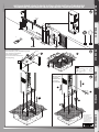 3
3
-
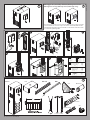 4
4
-
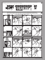 5
5
-
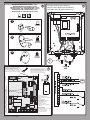 6
6
-
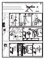 7
7
-
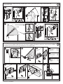 8
8
-
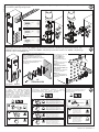 9
9
-
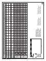 10
10
-
 11
11
-
 12
12
-
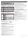 13
13
-
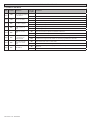 14
14
-
 15
15
-
 16
16
-
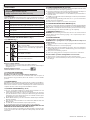 17
17
-
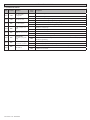 18
18
-
 19
19
-
 20
20
-
 21
21
-
 22
22
-
 23
23
-
 24
24
-
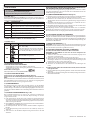 25
25
-
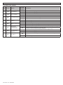 26
26
-
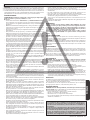 27
27
-
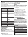 28
28
-
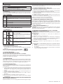 29
29
-
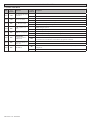 30
30
-
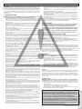 31
31
-
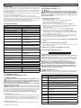 32
32
-
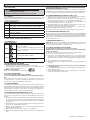 33
33
-
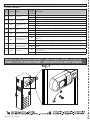 34
34
-
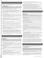 35
35
-
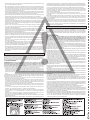 36
36


BFT MOOVI 30 Bedienungsanleitung
- Typ
- Bedienungsanleitung
- Dieses Handbuch eignet sich auch für
in anderen Sprachen
- English: BFT MOOVI 30 Owner's manual
- français: BFT MOOVI 30 Le manuel du propriétaire
- español: BFT MOOVI 30 El manual del propietario
- italiano: BFT MOOVI 30 Manuale del proprietario
- Nederlands: BFT MOOVI 30 de handleiding
Verwandte Artikel
-
BFT Sub BT Bedienungsanleitung
-
-
BFT Virgo Smart BT A Benutzerhandbuch
-
-
-
-
-
-
Andere Dokumente
-
Telcoma BR-6 Bedienungsanleitung
-
DEA TRAFIK_N Bedienungsanleitung
-
-
 Beninca DA.24V Operating Instructions Manual
-
-
V2 Elettronica V2 Wally2 Bedienungsanleitung
-
CAME ZL38 Bedienungsanleitung
-
Vimar EBR2 Installationsanleitung
-
Bauer ARGO G Installationsanleitung
-
Genius SPIN 3 4 6 424 Bedienungsanleitung
