
FRAGMA 6A
Manuale per il collegamento e l’uso - Installation and operation manual
Manuel pour le raccordement et l’emploi - Manual para el conexionado y el uso
Installations und Benutzerhandbuch - Εγχειρίδιο σύνδεσης και χρήσης
EBR2
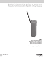
Barriera 230 V per aste da 5/6 m
Barrier 230 V for bars up to 5/6 m long
Barrière 230 V pour barres de 5/6 m
Barrera 230 V para barras de 5/6 m
Schranke 230 V für Stangen 5/6 m
Σύστημα μπάρας 230 V για μπάρες 5/6 m

2
FRAGMA
CONSERVARE CON CURA QUESTE ISTRUZIONI
1° - Se non é previsto nella centralina elettrica, installare a
monte della medesima un’interruttore di tipo magnetotermico
(onnipolare con apertura minima dei contatti pari a 3mm) che
riporti un marchio di conformità alle normative internazionali.
Tale dispositivo deve essere protetto contro la richiusura
accidentale (ad esempio installandolo dentro quadro chiuso
a chiave).
2° - Per la sezione ed il tipo dei cavi la ELVOX consiglia di
utilizzare un cavo di tipo H05RN-F con sezione minima di
1,5mm2 e comunque di attenersi alla norma IEC 364 e alle
norme di installazione vigenti nel proprio Paese.
3° - Posizionamento di un’eventuale coppia di fotocellule: Il
raggio delle fotocellule deve essere ad un’altezza non
superiore a 70 cm dal suolo e ad una distanza dal piano di
movimento dell’anta non superiore a 20 cm. Il loro corretto
funzionamento deve essere verificato a fine installazione in
accordo al punto 7.2.1 della EN 12445.
N.B.: È obbligatoria la messa a terra dell’impianto
I dati descritti nel presente manuale sono puramente indicativi.
ELVOX si riserva di modificarli in qualsiasi momento.
Realizzare l’impianto in ottemperanza alle norme ed alle leggi
vigenti.
ISTRUZIONI DI SICUREZZA IMPORTANTI
PER L’INSTALLAZIONE
- ATTENZIONE -
PER LA SICUREZZA DELLE PERSONE É IMPORTANTE
CHE VENGANO SEGUITE TUTTE LE ISTRUZIONI
SEGUIRE TUTTE LE ISTRUZIONI DI INSTALLAZIONE
1° - Questo libretto d’istruzioni è rivolto esclusivamente a
del personale specializzato che sia a conoscenza dei criteri
costruttivi e dei dispositivi di protezione contro gli infortuni per
i cancelli, le porte e i portoni motorizzati (attenersi alle norme
e alle leggi vigenti).
2° - L’installatore dovrà rilasciare all’utente finale un libretto di
istruzioni in accordo alla EN 12635.
3° - L’installatore prima di procedere con l’installazione deve
prevedere l’analisi dei rischi della chiusura automatizzata
finale e la messa in sicurezza dei punti pericolosi identificati
(seguendo le norme EN 12453/EN 12445).
4° - Il cablaggio dei vari componenti elettrici esterni all’operatore
(ad esempio fotocellule, lampeggianti, ecc.) deve essere
effettuato secondo la EN 60204-1 e le modifiche a questa
apportate dal punto 5.2.2 della EN 12453.
5° - L’eventuale montaggio di una pulsantiera per il comando
manuale del movimento deve essere fatto posizionando la
pulsantiera in modo che chi la aziona non si trovi in posizione
pericolosa; inoltre si dovrà fare in modo che sia ridotto il
rischio di azionamento accidentale dei pulsanti.
6° - Tenete i comandi dell’automatismo (pulsantiera, telecomando
etc.) fuori dalla portata dei bambini. I comandi devono essere
posti ad un’altezza minima di 1,5 m dal suolo e fuori dal
raggio d’azione delle parti mobili.
7° - Prima di eseguire qualsiasi operazione di installazione,
regolazione, manutenzione dell’impianto, togliere la tensione
agendo sull’apposito interruttore magnetotermico collegato a
monte dello stesso.
LA DITTA ELVOX NON ACCETTA NESSUNA RESPONSABILITÀ
per eventuali danni provocati dalla mancata osservanza
nell’installazione delle norme di sicurezza e delle leggi attualmente
in vigore.
Direttiva 2002/96/CE (WEEE, RAEE).
Il simbolo del cestino barrato riportato sull’apparecchio indica che il prodotto, alla fine della propria vita utile, dovendo essere trattato separatamente dai rifiuti domestici, deve
essere conferito in un centro di raccolta differenziata per apparecchiature elettriche ed elettroniche oppure riconsegnato al rivenditore al momento dell’acquisto di una nuova
apparecchiatura equivalente.
L’utente è responsabile del conferimento dell’apparecchio a fine vita alle appropriate strutture di raccolta. L’adeguata raccolta differenziata per l’avvio successivo dell’apparecchio
dismesso al riciclaggio, al trattamento e allo smaltimento ambientalmente compatibile contribuisce ad evitare possibili effetti negativi sull’ambiente e sulla salute e favorisce
il riciclo dei materiali di cui è composto il prodotto. Per informazioni più dettagliate inerenti i sistemi di raccolta disponibili, rivolgersi al servizio locale di smaltimento rifiuti, o al
negozio in cui è stato effettuato l’acquisto.
Rischi legati alle sostanze considerate pericolose (WEEE).
Secondo la nuova Direttiva WEEE sostanze che da tempo sono utilizzate comunemente su apparecchi elettrici ed elettronici sono considerate sostanze pericolose per le
persone e l’ambiente. L’adeguata raccolta differenziata per l’avvio successivo dell’apparecchio dismesso al riciclaggio, al trattamento e allo smaltimento ambientalmente
compatibile contribuisce ad evitare possibili effetti negativi sull’ambiente e sulla salute e favorisce il riciclo dei materiali di cui è composto il prodotto.
I

1
FRAGMA
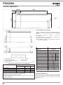
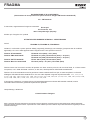
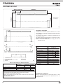
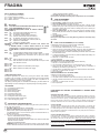
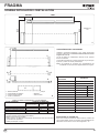
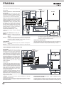
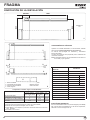
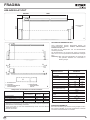
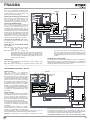
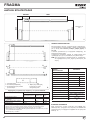
LAYOUT IMPIANTO
1
280x300
6000
1065
1000
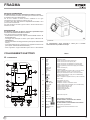
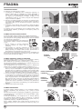
CARATTERISTICHE TECNICHE
Attuatore irreversibile ambidestro, con centrale incorporata,
utilizzato per movimentare in modo intensivo aste lunghe da
3 a 6 m.
La colonna è protetta con cataforesi e verniciatura
termoindurente.
L’asta della barriera con profilo ELVOX è predisposta per
l’inserimento di una costa pneumatica.
N.B. È obbligatorio uniformare le caratteristiche dell’impianto
alle norme e leggi vigenti.
FISSAGGIO FRAGMA 6A
Dopo aver cementato il basamento di fissaggio (cod. EBRB)
nella posizione ritenuta ideale, procedere nel fissaggio della
FRAGMA 6A utilizzando i dadi in dotazione e una chiave
esagonale n° 19.
TIPO DI COMANDO USO DELLA CHIUSURA
Persone esperte Persone esperte
Uso illimitato
(fuori da area pubblica*) (area pubblica)
a uomo presente A B
a impulsi in vista (es. sensore) C C C e D
a impulsi non in vista (es. telecomando) C C e D C e D
automatico C e D C e D C e D
* esempio tipico sono le chiusure che non accedono a pubblica via
A: Pulsante di comando a uomo presente (cioè ad azione mantenuta).
B: Selettore a chiave a uomo presente, come cod. EDS1.
C: Gomme come cod. EBRG e/o altri dispositivi di limitazione delle forze entro i limiti della norma
EN12453 - Appendice A.
D: Fotocellule, come cod. EFA1.
Componenti da installare secondo la norma EN12453
Misure in
mm
1 - Barriera FRAGMA 6A
2 - Fotocellule di sicurezza
3 - Colonnina porta fotocellula zincata
4 - Profilo in gomma
5 - Sensore magnetico
- Selettore a chiave
- Antenna radio
2
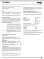
CARATTERISTICHE
TECNICHE
Lunghezza max. asta
Tempo di apertura
Alimentazione e frequenza
Potenza motore
Assorbimento
Condensatore
Coppia max sull’albero porta asta
Cicli consigliati al giorno
Servizio
Cicli consecutivi garantiti
Tipo di olio
Peso max
Temperatura di lavoro
Grado di protezione
m 6
s 6
230 V~ 50 Hz 60 Hz
W 242 285
A 1,07 1,31
μF 10 10
Nm 155 141
n° 1500
100 %
n° 1500
SHELL OMALA S2 G100
kg 62
°C -10 ÷ +55
IP 54
FRAGMA 6A
5
1
4
2
2
2
2
2
2
3
3 3
3
3
3
I

2
FRAGMA
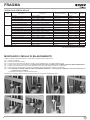
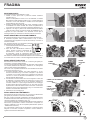
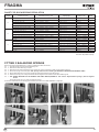
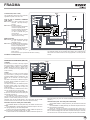
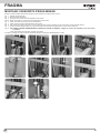
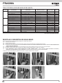
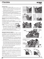
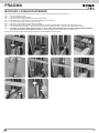
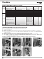
Togliere il contenitore del quadro elettronico in modo da creare spazio all’interno della colonna.
Fig. 1 - Svitare le due ghiere.
Fig. 2 - Rimuovere il bilanciere inferiore.
Fig. 3 - Togliere i due inserti plastici tondi dal tubo centrale in quanto utilizzati solo per il montaggio della terza molla.
Fig. 4 - Inserire le due molle sui tubi laterali. N.B. La scelta delle molle deve essere eseguita secondo la TABELLA SCELTA E REGOLAZIONE MOLLE.
Fig. 5 - Calzare il bilanciere inferiore in modo che la superficie dei due inserti plastici vada a contatto con le molle laterali.
Fig. 6 - Avvitare la prima ghiera in modo che il lato con la superficie liscia più grande vada a contatto con il bilanciere.
Fig. 7 - N.B.: AVVITARE LA GHIERA COME DA TABELLA SUPERIORE (TIRAGGIO H - vedere paragrafo “Regolazione molle di bilanciamento)) con
l’apposita chiave in dotazione.
Avvitare la seconda ghiera in modo da bloccare la prima.
Procedere con il montaggio dell’asta secondo le indicazioni descritte nel paragrafo “MONTAGGIO ASTA”.
MONTAGGIO 2 MOLLE DI BILANCIAMENTO
1
5
2
6
3
7
4
I
Vedi paragrafo “Regolazione molle di bilanciamento”
GUIDA ALLA SCELTA MOLLE
Lunghezza
asta
Configurazione asta
e accessori
Codici asta
e accessori
Molle da installare Codici molle Tiraggio
3 m
Asta e mozzo EBRA.380 + EBRM.80 3 molle Ø 4 mm 3xEBRM.4 20
Asta, mozzo e appoggio mobile EBRA.380 + EBRM.80 + EBRP.M 2 molle Ø 4,5 mm 2xEBRM.4.5 20
Asta, mozzo e prolo gomma EBRA.380 + EBRM.80 + EBRG.3 2 molle Ø 4,5 mm 2xEBRM.4.5 20
Asta, mozzo e siepe EBRA.380 + EBRM.80 + EBRS.3 2 molle Ø 4,5 mm 2xEBRM.4.5 20
Asta, mozzo, prolo gomma e appoggio mobile EBRA.380 + EBRM.80 + EBRG.3 + EBRP.M 2 molle Ø 4,5 mm 2xEBRM.4.5 25
Asta, mozzo, siepe e appoggio mobile EBRA.380 + EBRM.80 + EBRS.3 + EBRP.M 2 molle Ø 4,5 mm 2xEBRM.4.5 25
4 m
Asta e mozzo EBRA.480 + EBRM.80 1 molla Ø 4 mm, 2 molle Ø 4,5 mm 1xEBRM.4 + 2xEBRM.4.5 20
Asta, mozzo e appoggio mobile EBRA.480 + EBRM.80 + EBRP.M 3 molle Ø 4,5 mm 3xEBRM.4.5 20
Asta, mozzo e prolo gomma EBRA.480 + EBRM.80 + EBRG.4 3 molle Ø 4,5 mm 3xEBRM.4.5 20
Asta, mozzo e siepe EBRA.480 + EBRM.80 + 2xEBRS.2 3 molle Ø 4,5 mm 3xEBRM.4.5 20
Asta, mozzo, prolo gomma e appoggio mobile EBRA.480 + EBRM.80 + EBRG.4 + EBRP.M 2 molle Ø 4,5 mm, 1 molla Ø 5 mm 2xEBRM.4.5 + 1xEBRM.5 20
asta, mozzo, siepe e appoggio mobile EBRA.480 + EBRM.80 + 2xEBRS.2 + EBRP.M 1 molla Ø 4,5 mm, 2 molle Ø 5 mm 1xEBRM.4.5 + 2xEBRM.5 20
5 m
Asta e mozzo EBRA.580 + EBRM.80 1 molla Ø 4,5 mm, 2 molle Ø 5 mm 1xEBRM.4.5 + 2xEBRM.5 20
Asta, mozzo e appoggio mobile EBRA.580 + EBRM.80 + EBRP.M 2 molle Ø 5 mm, 1 molla Ø 5,5 mm 2xEBRM.5 + 1xEBRM.5.5 15
Asta, mozzo e prolo gomma EBRA.580 + EBRM.80 + EBRG.5 2 molle Ø 5 mm, 1 molla Ø 5,5 mm 2xEBRM.5 + 1xEBRM.5.5 15
Asta, mozzo e siepe EBRA.580 + EBRM.80+EBRS.2+EBRS.3 1 molla Ø 5 mm, 2 molle Ø 5,5 mm 1xEBRM.5 + 2xEBRM.5.5 15
Asta, mozzo, prolo gomma e appoggio mobile EBRA.580 + EBRM.80 + EBRG.5 + EBRP.M 3 molle Ø 5,5 3xEBRM.5.5 20
Asta, mozzo, siepe e appoggio mobile EBRA.580 + EBRM.80+EBRS.2+EBRS.3 + EBRP.M 3 molle Ø 5,5 3xEBRM.5.5 20
6 m Asta e mozzo EBRA.680 + EBRM.80 3 molle Ø 5,5 3xEBRM.5.5 15

3
FRAGMA
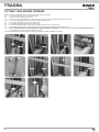
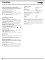
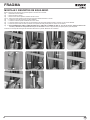
Togliere il contenitore del quadro elettronico in modo da creare spazio all’interno della colonna.
Fig. 1 - Svitare le due ghiere.
Fig. 2 - Rimuovere il bilanciere inferiore.
Fig. 3 - Togliere i due inserti plastici tondi dal tubo centrale.
Fig. 4-5 - Montare gli inserti sulla molla che verrà inserita nel tubo centrale.
Fig. 6 - Inserire le altre due molle sui tubi laterali.
Fig. 7 - Inserire la molla appena assemblata nel tubo centrale.
Fig. 8 - Calzare il bilanciere inferiore in modo che la superficie dei due inserti plastici vada a contatto con le molle laterali.
Fig. 9 - Avvitare la prima ghiera in modo che il lato con la superficie liscia più grande vada a contatto con il bilanciere.
Fig. 10 - N.B. AVVITARE LA GHIERA COME DA TABELLA A PAGINA 4 (TIRAGGIO H -
vedere paragrafo “Regolazione molle di bilanciamento
)
con l’apposita chiave in dotazione
.
Avvitare la seconda ghiera in modo da bloccare la prima.
Procedere con il montaggio dell’asta secondo le indicazioni descritte nel paragrafo “MONTAGGIO ASTA”.
MONTAGGIO 3 MOLLE DI BILANCIAMENTO
1
5
2
9
10
8
3
7
4
6
I

4
FRAGMA
I
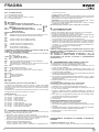
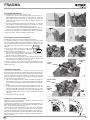
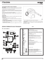
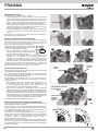
MONTAGGIO ASTA
Il montaggio dell’asta viene effettuato in 3 fasi:
1 - Inserire il mozzo porta asta in posizione verticale sull’albero
scanalato (Fig. 3).
Fissare la contropiastra al mozzo con 2 viti DTB10X50, 2 rondelle
DRL10X20Z e 2 dadi autobloccanti M10 (Fig. 4), facendo attenzione
a serrare le viti in modo alternato in maniera che la contropiastra
risulti parallela al piano del mozzo.
2 - Fissare il cavallotto alla base del porta mozzo, mediante le quattro
viti DTB8X20I e le relative rondelle. Non serrare completamente le
viti in modo da consentire il successivo inserimento dell’asta (Fig. 5).
3 - Applicare i due tappi in plastica alle estremità dell’asta ed infilare
l’asta nel mozzo. Serrare con forza le quattro viti DTB8X20I (Fig. 6).
L’operatore è di tipo irreversibile e non necessita di alcun tipo di
bloccaggio esterno per mantenere un’efficace posizione di chiusura.
REGOLAZIONE MOLLE DI BILANCIAMENTO
Normalmente la barriera viene fornita priva di molle di bilanciamento.
È necessario acquistare molle di bilanciamento di tipo e numero
corrispondente alla lunghezza e al tipo di asta ed al tipo e numero di
accessori installati.
Con operatore sbloccato, se l’asta tende a precipitare, agire sulle molle
di bilanciamento nel seguente modo:
1 - A motoriduttore bloccato sollevare elettricamente
l’asta fino alla verticale.
2 - Dopo aver tolto l’alimentazione elettrica al
motore, avvitare la ghiera di regolazione del
bilanciamento in senso orario in modo tale
da aumentare il grado di compressione delle molle durante il
movimento. Utilizzare la seconda ghiera per bloccare la prima.
Per verificare il corretto bilanciamento dell’asta sbloccare il motoriduttore
e muovere l’asta con la mano. L’asta deve leggermente tendere a salire.
REGOLAZIONE FINECORSA
Normalmente la barriera viene fornita con i finecorsa già regolati per
permettere il movimento ideale dell’asta.
In caso di errato livellamento della piastra da cementare, l’asta potrebbe
non risultare perfettamente orizzontale o verticale con un conseguente
cattivo risultato estetico dell’installazione.
Per ovviare a ciò è possibile modificare la corsa dell’asta intervenendo
sui finecorsa meccanici (Fig. 7):
1 - A barriera sbloccata, utilizzare una chiave esagonale n° 19 per
sbloccare i dadi di fermo (F) e una chiave a brugola n° 8 per svitare
o riavvitare le viti a testa svasata (G) di regolazione dei finecorsa
meccanici in modo da delimitare immediatamente il nuovo arco
descritto dall’asta della barriera.
2 - Così facendo i finecorsa elettrici sono ora da regolare in modo tale
da delimitare il movimento elettrico del motore per la nuova corsa
che l’asta deve descrivere. Per far ciò è necessario utilizzare un
cacciavite a stella con il quale vengono allentate le viti di fissaggio
(E) delle camme del finecorsa elettrico (Fig. 8). Una volta che l’asta
è posizionata in base alla battuta di fermo meccanico è sufficiente
spostare le camme come rappresentato in Fig. 9 in modo tale da far
scattare il microinterruttore di finecorsa.
3 - Ribloccare la vite di fissaggio (E).
REGOLAZIONE RALLENTAMENTO
Normalmente la barriera viene fornita con i finecorsa di rallentamento
già regolati per permettere il movimento ideale dell’asta.
Nel caso vi fosse la necessità di modificare i parametri di rallentamento
è sufficiente intervenire sulle relative camme (Fig. 10) allentando con un
cacciavite a stella le viti di fissaggio K (Fig. 10).
Le camme di rallentamento sono indipendenti dalle camme di regolazione
del finecorsa (muovendole le camme di Chiusura e di Apertura non
vengono modificate) e sono tra loro separate (Rallentamento Apertura
- Rallentamento Chiusura).
Una volta regolate, ribloccare la vite di fissaggio e verificare facendo
eseguire un movimento completo di apertura e chiusura dell’asta il
regolare funzionamento della barriera.
11
4
3
5 6
H mm
8
E
7
G
F
10
K
CAMME RALLENTAMENTO
CHIUSURA
CAMME
RALLENTAMENTO
APERTURA
9
CAMME
CHIUSURA
CAMME
APERTURA

5
FRAGMA
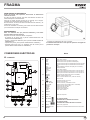
SBLOCCO DI EMERGENZA
Da effettuare dopo aver tolto l’alimentazione elettrica al motore.
In caso di mancanza di corrente, per poter aprire manualmente la sbarra
è necessario sbloccare l’elettroriduttore.
Per far ciò si utilizza la chiave ELVOX in dotazione e la si gira
manualmente in senso orario fino al fermo (Fig. 12).
In questo modo l’asta della barriera è indipendente dal riduttore e la si
può muovere manualmente.
Una volta tornata la corrente si gira la chiave in senso antiorario fino a
bloccare con forza.
MANUTENZIONE
Da effettuare solamente da parte di personale specializzato dopo
aver tolto l’alimentazione elettrica al motore.
Ogni 100.000 manovre complete verificare:
- il bilanciamento dell’asta (vedi capitolo “REGOLAZIONE MOLLE DI
BILANCIAMENTO”);
- il serraggio della manopola di sblocco (vedi capitolo “SBLOCCO DI
EMERGENZA”);
- il serraggio del mozzo e il fissaggio dell’asta (vedi capitolo “MONTAGGIO
ASTA”);
- l’usura delle battute di fermo meccanico e la regolazione dei finecorsa
(vedi capitolo “REGOLAZIONE FINECORSA”);
- inoltre, ingrassare i supporti dell’albero porta asta e la barra filettata
guidamolla.
La manutenzione sopra descritta è vitale per il corretto
funzionamento del prodotto nel tempo.
12
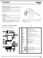
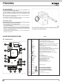
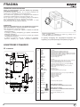
TR2
J10
J3
J5
J9
J1
J8
J7
J6
J4
S3
J2
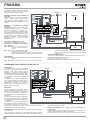
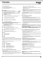
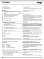
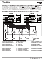
Alimentazione 230 Vac 50/60 Hz
Comune dei contatti
Contatto finecorsa che ferma la chiusura (NC)
Contatto finecorsa che ferma l’apertura (NC)
Contatto finecorsa per inizio rallentamento in chiusura (NO)
Contatto finecorsa per inizio rallentamento in apertura (NO)
Contatto segnalazione presenza veicolo (NO) (solo in modalità
PARK)
Contatto fotocellule (NC)
-
Comune dei contatti
Positivo per alimentazione autotest costa a 12 Vdc max 500 mA
Positivo Alimentazione accessori a 12 Vdc max 500 mA
Negativo per alimentazione accessori a 12 Vdc max 500 mA
Contatto pulsante di apertura 2 (NA) (solo in modalità PARK)
Spia barriera aperta 12 Vdc
Buzzer - Collegamento segnalatore sonoro (12 Vdc max 200 mA)
Antenna radio
Lampeggiatore (max 40 W )
Collegamento comune motore
Collegamento invertitori e condensatore motore
Contatto comando chiusura immediata (solo in modalità PARK)
Contatto pulsante di apertura 1 (NA)
Contatto pulsante di chiusura (NA)
Contatto pulsante stop (NC)
Contatto impulso singolo (NA)
Comune dei contatti
-
Modulo radio incorporato
-
NON TOCCARE IL PONTICELLO !
SE VIENE RIMOSSO L’OPERATORE NON FUNZIONA!
NON TOCCARE IL PONTICELLO !
SE VIENE RIMOSSO IL RADIOCOMANDO NON FUNZIONA!
Pulsante per la programmazione.
Regolazione della velocità di rallentamento solo in
chiusura
J1
J2
J3
J4
J5
J6
J7
J8
J9
J10
S3
TR2
L-N
COM
LSC
LSO
LSSC
LSSO
TLC
PHOT. NC
EDGE NC
COM
D+ TEST
D+
D-
OPEN 2
SIGNAL
AERIAL
U - MOTOR
V-W - MOTOR
OK CLOSE
OPEN 1
CLOSE
STOP
K BUTT.
COM
PROBE
RADIO
AUX. ATT.
SW PARK
SW RADIO
PROG.
TRIMMER LOW
SPEED
COLLEGAMENTI ELETTRICI
RS15
A - CONNESSIONI
I

6
FRAGMA
RELE’ E COMANDO MOTORE
K1 => Comando direzione apertura
K2 => Comando direzione chiusura
Q4 => TRIAC - Comando motore in apertura e chiusura
Q5 => Comando lampeggiatore
B - SETTAGGI
SW1 SW2 - MICROINTERRUTTORI PER PROCEDURE
DIP 1 - CONTROLLO SENSO DI ROTAZIONE DEL MOTORE (ON)
(PUNTO C)
DIP 2 - PROGRAMMAZIONE TEMPI (ON) (PUNTO D)
DIP 1-2 MEMORIZZAZIONE/CANCELLAZIONE CODICI
RADIO (PUNTO E)
MICROINTERRUTTORI DI GESTIONE
DIP 3
ON - Abilitazione tempo di attesa prima della chiusura automatica (max 5 min.)
OFF - Disabilitazione tempo di attesa prima della chiusura automatica
DIP 4
ON - Comando ricevitore radio in modalità Automatica
OFF - Comando ricevitore radio in modalità Passo Passo
DIP 5
ON - Comando pulsante K in modalità Automatica
OFF - Comando pulsante K in modalità Passo Passo
DIP 6
ON - Funzionamento in modalità PARK
OFF - Funzionamento in modalità NORMALE
ATTENZIONE: LA SCHEDA PARK TRAMITE IL DIP 6 ABILITA O MENO ALCUNI
COMANDI PERTANTO PRESTARE ATTENZIONE:
SE DIP 6 OFF - FUNZIONALITA’ NORMALE
I COMANDI APERTURA 2, OK CLOSE E TLC (TRAFFIC LIGHT CONTROL)
NON SONO ATTIVI.
SE DIP 6 ON - FUNZIONALITA’ PARK
TUTTI I COMANDI SONO ABILITATI
DIP 7 OFF
DIP 8 - Controllo in modalità Park della funzione del tasto APERTURA 2
ON - il tasto APERTURA 2 è sempre abilitato
OFF - il tasto APERTURA 2 è abilitato solo se non c’è presenza mezzo su sensore
magnetico collegato a TLC (Traffic Light Control)
DIP 9 OFF
DIP 10 - Funzionamento dopo black-out
ON - La sbarra chiude se non totalmente chiusa
OFF - La sbarra rimane ferma nel punto in cui è avvenuto il black-out
DIP 11 OFF
DIP 12 OFF
DIP 13 - Gestione lampeggiatore
ON - Alimentazione intermittente
OFF - Alimentazione fissa
DIP 14 ON
DIP 15 OFF
DIP 16 OFF
REGOLATORE DELLA VELOCITA’ DI RALLENTAMENTO
La regolazione del rallentamento viene fatta ruotando il Trimmer LOW SPEED
che serve a variare la velocità del motore in fase di accostamento di fine chiusura
(ruotandolo in senso orario si da più velocità al motore). In apertura la regolazione
non è disponibile.
Il rallentamento viene determinato automaticamente dai finecorsa a circa 30° prima
del raggiungimento del finecorsa di apertura o di chiusura.
SEGNALAZIONI LED
DL1 - (Rosso) - Programmazione attivata
DL2 - (Rosso) - Contatto di stop (NC)
DL3 - (Verde) - Sbarra in apertura
DL4 - (Rosso) - Sbarra in chiusura
DL5 - (Rosso) - Contatto fotocellule (NC)
DL6 - (Rosso) - Contatto costa (NC)
DL7 - (Rosso) - Contatto finecorsa di chiusura (NC)
DL8 - (Rosso) - Contatto finecorsa di apertura (NC)
DL9 - (Verde) - Programmazione radio attivata
C - TARATURA RALLENTAMENTO DEL MOTORE
Questo controllo ha il compito di agevolare l’installatore durante la messa in opera
dell’impianto, o durante eventuali controlli successivi.
1 - Mettere DIP1 su ON, il led rosso DL1 inizia a lampeggiare.
2 - Premere e mantenere premuto il pulsante PROG (il movimento è eseguito ad
uomo presente, apre-stop-chiude-stop-apre-ecc.). Con il led verde DL3 acceso, la
sbarra si apre. Con il led rosso DL4 acceso, la sbarra si chiude.
3 - Eseguire la taratura della velocità di rallentamento:
- Posizionare il trimmer LOW SPEED al minimo
- Premere e mantenere premuto il pulsante PROG
- Verificare l’attivazione della velocità di rallentamento al raggiungimento dei
finecorsa LSSC ed LSSO
- Regolare il trimmer LOW SPEED.
ATTENZIONE: Verificare che il motore abbia abbastanza forza per movimentare
l’asta in chiusura. In caso contrario aumentare il valore settato sul trimmer fino al
raggiungimento della condizione ottimale di funzionamento.
ATTENZIONE: In zone soggette a temperature particolarmente rigide, ruotare il
trimmer, in senso orario, di 5° in più rispetto al valore normale
4 - Al termine del controllo rimettere DIP1 in posizione OFF => Il led DL1 si spegne
segnalando l’uscita dal controllo.
N.B.: Durante questo controllo la costa e le fotocellule non sono attivi.
D - PROGRAMMAZIONE TEMPI
1 - Chiudere completamente la barriera.
2 - Mettete il microinterruttore DIP 2 su ON, il led rosso DL1 inizia a lampeggiare.
3 - Premete e poi rilasciare il pulsante PROG. La sbarra apre.
4 - Raggiunto la completa apertura, la sbarra si ferma e si attiva il conteggio del tempo
d’attesa prima della chiusura automatica (max 5 minuti).
5 - Quando il tempo di pausa prima della chiusura automatica è sufficiente, o nel caso
non sia necessario, premere e poi rilasciare il pulsante PROG.
6 - La barriera chiude e, nello stesso istante, il led rosso DL1 smette di lampeggiare
segnalando l’uscita dalla procedura di apprendimento. Da questo momento le
sicurezze o altri comandi della barriera funzioneranno normalmente (inversioni,
stop, allarmi, ecc...). La chiusura della sbarra verrà eseguita in modalità veloce e
in prossimità della totale chiusura in modalità rallentata.
7 - Riposizionare DIP 2 su OFF.
8 - Fine procedura.
DURANTE LA PROGRAMMAZIONE LE SICUREZZE SONO ATTIVE ED IL LORO
INTERVENTO FERMA LA PROGRAMMAZIONE (IL LED DL1 DA LAMPEGGIANTE
RIMANE ACCESO FISSO).
PER RIPETERE LA PROGRAMMAZIONE POSIZIONARE IL DIP 2 SU
OFF, CHIUDERE LA SBARRA TRAMITE LA PROCEDURA “TARATURA
RALLENTAMENTO DEL MOTORE” E RIPETERE LA PROGRAMMAZIONE
SOPRA DESCRITTA.
E - PROGRAMMAZIONE CODICI RADIO (40 CODICI MAX)
La programmazione può essere eseguita solo a barriera ferma.
1 - Posizionare DIP 1 su ON e successivamente il DIP 2 su ON.
2 - Il led rosso DL1 di programmazione lampeggia con frequenza di 1 sec. ON
e 1 sec. OFF per 10 secondi.
3 - Premere il tasto del telecomando (normalmente il canale A) entro i 10
secondi impostati. Se il telecomando viene correttamente memorizzato il led
DL9 (verde) emette un lampeggio.
4 - Il tempo di programmazione dei codici si rinnova automaticamente per poter
memorizzare il telecomando successivo.
5 - Per terminare la programmazione lasciare trascorrere 10 sec., oppure
premere per un attimo il pulsante PROG. Il led rosso DL1 di programmazione
smette di lampeggiare.
6 - Riposizionare DIP 1 su OFF e DIP 2 su OFF.
7 - Fine procedura.
PROCEDURA CANCELLAZIONE DI TUTTI I CODICI RADIO
La cancellazione può essere eseguita solo a barriera ferma.
1 - Posizionare il DIP 1 su ON e successivamente il DIP 2 su ON.
2 - Il led rosso DL1 di programmazione lampeggia con frequenza di 1 sec. ON
e 1 sec. OFF per 10 secondi.
3 - Premere e mantenere premuto il pulsante PROG per 5 secondi. La
cancellazione della memoria viene segnalata da due lampeggi del led verde
DL9.
4 - Il led rosso DL1 di programmazione rimane attivo ed è possibile inserire
nuovi codici come da procedure sopra descritte.
5 - Riposizionare DIP 1 su OFF e DIP 2 su OFF.
6 - Fine procedura.
SEGNALAZIONE MEMORIA SATURA CODICI RADIO
La segnalazione si può ottenere solo a barriera ferma.
1 - Posizionare il DIP 1 su ON e successivamente il DIP 2 su ON.
2 - Il led verde DL9 lampeggia per 6 volte segnalando memoria satura (40 codici
presenti).
3 - Successivamente il led DL1 di programmazione rimane attivo per 10 secondi,
consentendo un eventuale cancellazione totale dei codici.
4 - Riposizionare DIP 1 su OFF e DIP 2 su OFF.
5 - Fine procedura.
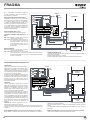
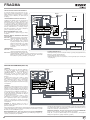
FUNZIONAMENTO ACCESSORI DI COMANDO IN MODALITA’
NORMALE
PULSANTE DI APERTURA 1 (Com - Open 1)
A sbarra ferma il pulsante comanda il moto di apertura. Se viene azionato durante
I

7
FRAGMA
la chiusura fa riaprire la sbarra. In modalità di
funzionamento Park (DIP 6 ON) abilita l’apertura
della sbarra per entrare nel parcheggio.
FUNZIONE OROLOGIO DEL PULSANTE DI
APERTURA
La Funzione Orologio è utile nelle ore di punta,
quando il traffico veicolare risulta rallentato
(es. entrata/uscita operai, emergenze in zone
residenziali o parcheggi e, temporaneamente, per
traslochi).
MODALITÁ DI APPLICAZIONE FUNZIONE
OROLOGIO
Collegando un interruttore e/o un orologio di tipo
giornaliero/settimanale (al posto o in parallelo
al pulsante di apertura N.A. “morsetti Com -
Open 1”), è possibile aprire e mantenere aperta
l’automazione finché l’interruttore viene premuto
o l’orologio rimane attivo. Ad automazione aperta
vengono inibite tutte le funzioni di comando.
Rilasciando l’interruttore, o allo scadere dell’ora
impostata, si avrà la chiusura immediata
dell’automazione.
PULSANTE DI CHIUSURA (Com - Close)
A sbarra aperta comanda il moto di chiusura.
PULSANTE DI COMANDO PASSO-PASSO
(Com - K Button)
DIP5 - OFF => Esegue un comando ciclico dei
comandi apre-stop-chiude-stop-
apre-ecc.
DIP5 - ON => Esegue l’apertura a sbarra chiusa.
Se azionato durante il movimento
di apertura non ha effetto. Se azionato con sbarra aperta, la
chiude. Se azionato durante il movimento di chiusura la fa riaprire.
TELECOMANDO
DIP4 - OFF => Esegue un comando ciclico dei comandi apre-stop-chiude-stop-
apre-ecc.
DIP4 - ON => Esegue l’apertura a sbarra chiusa. Se azionato durante il
movimento di apertura non ha effetto. Se azionato con sbarra
aperta, la chiude. Se azionato durante il movimento di chiusura
la fa riaprire.
CHIUSURA AUTOMATICA (DIP 3)
I tempi di pausa prima di avere la chiusura automatica della sbarra vengono
registrati durante la programmazione dei tempi.
Il tempo di pausa massimo è di 5 minuti.
Il tempo di pausa è attivabile o disattivabile tramite DIP3 (ON - attivo).
_
+
+
_
_
+
+
NC
D-
+
D
+D
NO
COM
SS
D-
-
+
PASSO PASSO
STOP
CHIUDE
APRE 1
ANTENNA
LED
BUZZER
CALZA
ANTENNA
ENTRATA
SENSORE MAGNETICO
USCITA
R=2K2
TIMER
LSC
LSO
LSSC
LSSO
12 Vdc max 0,5A per ACCESSORI
12 Vdc max 0,5A per AUTOTEST PER COSTA
PER ENTRARE:
A condizione che un’autovettura sia presente
sul sensore magnetico, può essere comandata
l’apertura della sbarra tramite pulsante
APERTURA 1, K BUTTON o comando RADIO.
La sbarra rimarrà aperta fin quando l’autovettura
non sarà transitata davanti alle fotocellule situate
in corrispondenza della linea di completamento
del passaggio.
La chiusura viene eseguita immediatamente
dopo l’avvenuto transito (fotocellula liberata), e
viene protetta da fotocellule e/o costa. Queste
comanderanno l’inversione della sbarra in
apertura anche se l’autovettura permane nel
raggio di azione delle sicurezze.
PER USCIRE:
L’apertura della sbarra è consentita tramite il
pulsante APERTURA 2 collegato ad un sensore
magnetico o altro dispositivo, a condizione che
non vi siano mezzi sul sensore magnetico di
ingresso (vedi DIP 8 per esclusione del blocco di
precedenza).
La sbarra rimarrà aperta fin quando l’autovettura
non sarà transitata davanti alle fotocellule situate
in corrispondenza della linea di completamento
del passaggio.
La chiusura viene eseguita immediatamente
dopo l’avvenuto transito (fotocellula liberata), e
viene protetta da fotocellule e/o costa. Queste
comanderanno l’inversione della sbarra in apertura anche se l’autovettura
permane nel raggio di azione delle sicurezze.
ATTENZIONE: Il tempo di attesa prima della chiusura automatica sarà conteggiato
solo se “DIP 3 ON”.
Come conseguenza se “DIP 3 ON” e se l’autoveicolo rimane troppo a lungo sul
sensore magnetico senza transitare (senza impegnare la fotocellula), la sbarra
chiuderà dopo il tempo preimpostato.
PULSANTE APERTURA 2 (Com - Open 2) solo per funzionamento in
modalità PARK
Comando dedicato all’apertura della sbarra per uscire dal parcheggio con
gestione della segnalazione di precedenza del semaforo.
Questo comando viene escluso se il comando TLC risulta inserito (presenza
FUNZIONAMENTO DELLA MODALITA’ PARK (DIP 6 ON)
NO
NC
D+
D-
+
D-
S
D+
+
S
COM
+
_
+
_
-
+
PASSO PASSO
STOP
CHIUDE
APRE 1
ANTENNA
LED
BUZZER
CALZA
ANTENNA
SENSORE MAGNETICO
USCITA
SENSORE MAGNETICO
ENTRATA
R=2K2
12 Vdc max 0,5A per ACCESSORI
12 Vdc max 0,5A per AUTOTEST PER COSTA
I

8
FRAGMA
mezzo in ingresso). Se non si desidera utilizzare il blocco di precedenza tramite
l’ingresso TLC, posizionare il DIP 8 in ON.
COMANDO OK CLOSE (Com - OK Close) solo per funzionamento in modalità
PARK
Consente la chiusura immediata della sbarra dopo che il veicolo è transitato.
Contatto NO, normalmente questo comando viene dato da una fotocellula o da un
sensore magnetico posizionato sulla linea di chiusura della sbarra.
Se il comando rimane inserito la sbarra non richiude.
COMANDO TLC - Traffic Light Control (Com - TLC) solo per funzionamento
in modalità PARK
L’ingresso “TLC” (NO) deve essere collegato ad un sensore magnetico posizionato
nelle immediate vicinanze della sbarra, in tal modo fornisce la segnalazione di
presenza di un veicolo in ingresso (se non si vuole usufruire di questa funzione
eseguire un ponticello tra i morsetti Com e TLC). Solo la presenza di un veicolo
consente l’apertura della sbarra in modalità di funzionamento PARK tramite il
comando apertura 1.
FUNZIONAMENTO DOPO BLACK OUT
Con DIP 10 - OFF => Con mancanza della tensione di rete la sbarra rimane
ferma o se in movimento si ferma. Al ritorno della
tensione di rete è sufficiente premere il telecomando, i
pulsanti di APERTURA 1 o 2 o il pulsante K Button per
aprire la sbarra. A sbarra aperta date un comando di
chiusura o attendete il tempo di pausa prima della chiusura
automatica => La sbarra parte in chiusura => All’arrivo in
chiusura vengono ristabilite le funzionalità normali. Durante
il riallineamento le sicurezze sono attive.
Con DIP 10 - ON => Al ritorno della tensione di rete la sbarra chiude se aperta,
non chiude solo nel caso in cui sia attiva la funzione
orologio (vedi pulsante di APERTURA 1).
FUNZIONAMENTO ACCESSORI DI SICUREZZA
FOTOCELLULA (Com - Photo)
Con sbarra abbassata, se un ostacolo è interposto al raggio delle fotocellule e
viene comandata l’apertura, la sbarra apre (durante l’apertura le fotocellule non
interverranno).
Le fotocellule interverranno solo in fase di chiusura (con ripristino del moto inverso
dopo un secondo anche se le stesse restano impegnate).
N.B.: Si raccomanda di verificare la funzionalità delle fotocellule almeno
ogni 6 mesi.
ATTENZIONE: Se il led del ricevitore rimane acceso è possibile che siano
presenti dei disturbi sulla rete di alimentazione.
Vi consigliamo di collegare elettricamente a terra le
colonne o le colonnine di supporto alle fotocellule
al morsetto D- per proteggere le fotocellule da fonti
di disturbo.
Fate attenzione a non creare corto circuiti quando le
fasi di alimentazione sono invertite!
PULSANTE DI STOP (Com - Stop)
Durante qualunque operazione il pulsante di STOP esegue il fermo della sbarra.
Se premuto a sbarra aperta totalmente si esclude temporaneamente la chiusura
automatica (se selezionata tramite DIP3 ON).
É quindi necessario dare un nuovo comando per farla richiudere.
Al ciclo successivo la funzione “chiusura automatica” viene riattivata (se
selezionata tramite DIP3 ON).
LAMPEGGIATORE 230 V 40 W
DIP 13 ON
Il lampeggiatore viene alimentato ad intermittenza, con lampeggio di 500 mS on/
off in apertura e 250 mS on/off in chiusura.
In allarme da costa o autotest costa, l’uscita lampeggiatore cambia l’intermittenza
con 2 brevi lampeggi seguiti da 2 secondi di spento.
BUZZER (Opzionale) - (Com - Buzzer)
Durante l’apertura il buzzer darà un segnale sonoro intermittente che diventa più
frequente in chiusura.
In caso di intervento delle sicurezze (allarme) questo segnale sonoro aumenta la
frequenza dell’intermittenza.
Corrente fornita per il funzionamento del buzzer 200 mA a 12 Vdc.
SPIA DI SEGNALAZIONE BARRIERA APERTA (Com-Signal)
Ha il compito di segnalare gli stati della barriera aperta, parzialmente aperta
o comunque non chiusa totalmente. Solo a barriera completamente chiusa si
spegne.
N.B.: Se si eccede con le pulsantiere o con le lampade, la logica della centralina
ne risulterà compromessa con possibile blocco delle operazioni.
CARATTERISTICHE TECNICHE
- Umidità < 95% senza condensazione
- Tensione di alimentazione 230 V~ ±10 %
- Frequenza 50/60 Hz
- Assorbimento massimo scheda 30 mA
- Microinterruzioni di rete 100 ms
- Potenza massima spia barriera aperta 3 W (equivalente a 1
lampadina da 3 W o 5 led con
resistenza in serie da 2,2 kΩ)
- Carico massimo all’uscita lampeggiatore 40 W con carico resistivo
- Corrente disponibile per fotocellule e accessori 500 mA 12 Vdc
- Corrente disponibile su connettore radio 200 mA 12 Vdc
CARATTERISTICHE TECNICHE RADIO
- Frequenza Ricezione 433,92 MHz
- Impedenza 52 Ω
- Sensibilità >2,24 µV
- Tempo eccitazione 300 ms
- Tempo diseccitazione 300 ms
- Tutti gli ingressi devono essere utilizzati come contatti puliti perchè l’alimentazione
è generata internamente (tensione sicura) alla scheda ed è disposta in modo da
garantire il rispetto di isolamento doppio o rinforzato rispetto alle parti a tensione
pericolosa.
- Eventuali circuiti esterni collegati alle uscite della centralina, devono essere
eseguiti per garantire l’isolamento doppio o rinforzato rispetto alle parti a
tensione pericolosa.
- Tutti gli ingressi vengono gestiti da un circuito integrato programmato che
esegue un autocontrollo ad ogni avvio di marcia.
12 Vdc
Mors.
D-
I

9
FRAGMA
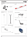
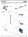
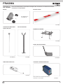
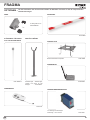
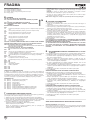
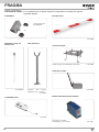
OPTIONAL - Per i collegamenti ed i dati tecnici degli accessori attenersi ai relativi libretti di istruzione.
PALETTO DI SUPPORTO
Paletto di supporto a forcella
compatibile con tutte le aste.
cod. EBRP
PALETTO PENDULO PER
ASTA Ø 80
Cod. EBRP.M
MOZZO
per asta Ø 80 mm
cod. EBRM.80
ADESIVI
cod. ZBNE
SENSORE A SPIRA MAGNETICA
Per apertura con automezzi
monocanale - 12-24 Vac/dc cod. ZR01
PIASTRA DI FISSAGGIO
Piastra di fissaggio da interrare cod. EBRB
GOMMA
cod. EBRG
cod. ETR5
TELECOMANDO
I

10
FRAGMA
DICHIARAZIONE CE DI CONFORMITA’
(Dichiarazione di incorporazione di quasi-macchine allegato IIB Direttiva 2006/42/CE)
No. : ZDT00443.00
Il sottoscritto, rappresentante il seguente costruttore
Elvox SpA
Via Pontarola, 14/a
35011 Campodarsego (PD) Italy
dichiara qui di seguito che i prodotti
ATTUATORI PER BARRIERE STRADALI - SERIE FRAGMA
Articoli
FRAGMA 3D, FRAGMA 4A, FRAGMA 6A
risultano in conformità a quanto previsto dalla(e) seguente(i) direttiva(e) comunitaria(e) (comprese tutte le modifiche
applicabili) e che sono state applicate tutte le seguenti norme e/o specifiche tecniche:
Direttiva BT 2006/95/CE: EN 60335-2-103 (2003) + A11 (2009)
Direttiva EMC 2004/108/CE: EN 61000-6-1 (2007), EN 61000-6-3 (2007) + A1 (2011)
EN 61000-6-2 (2005), EN 61000-6-4 (2007) + A1 (2011)
Direttiva R&TTE 1999/5/CE: EN 301 489-3 (2002), EN 300 220-3 (2000)
Direttiva Macchine 2006/42/CE EN 13241 (2003) + A1 (2011), EN 12453 (2000)
Dichiara inoltre che la messa in servizio del prodotto non deve avvenire prima che la macchina finale, in cui deve essere
incorporato, non è stata dichiarata conforme, se del caso, alle disposizioni della Direttiva 2006/42/CE.
Dichiara che la documentazione tecnica pertinente è stata costituita da Elvox SpA, è stata compilata in conformità
all’allegato VIIB della Direttiva 2006/42/CE e che sono stati rispettati i seguenti requisiti essenziali: 1.1.1, 1.1.2, 1.1.3,
1.1.5, 1.1.6, 1.2.1, 1.2.2, 1.2.6, 1.3.1, 1.3.2, 1.3.3, 1.3.4, 1.3.7, 1.3.8, 1.3.9, 1.4.1, 1.4.2, 1.5.1, 1.5.2, 1.5.4, 1.5.5, 1.5.6,
1.5.7, 1.5.8, 1.5.9, 1.6.1., 1.6.2, 1.7.1, 1.7.2, 1.7.3, 1.7.4, 4.1.2.
Si impegna a presentare, in risposta ad una richiesta adeguatamente motivata delle autorità nazionali, tutta la
necessaria documentazione giustificativa pertinente al prodotto.
Campodarsego, 06/05/2013
L’Amministratore Delegato
Nota: Il contenuto di questa dichiarazione corrisponde a quanto dichiarato nell’ultima revisione della dichiarazione ufficiale disponibile
prima della stampa di questo manuale. Il presente testo è stato adattato per motivi editoriali. Copia della dichiarazione originale può essere
richiesta a Elvox SpA
I

11
FRAGMA
KEEP THESE INSTRUCTIONS WITH CARE
1° - Install a thermal magnetic switch (omnipolar, with a minimum
contact opening of 3 mm) before the control board, in case
this is not provided with it. The switch shall be guaranteed
by a mark of compliance with international standards. Such
a device must be protected against accidental closing (e.g.
Installing it inside the control panel key locked container).
2° - As far as the cable section and the cable kind are concerned,
ELVOX suggests to use an H05RN-F cable, with a minimum
section of 1,5mm
2
, and to follow, In any case, the IEC 364
standard and Installation regulations In force In your Country.
3° - Positioning of an eventual pair of photocells: The beam of the
photocells must be at an height not above the 70 cm from the
ground, and, should not be more than 20 cm away from the
axis of operation of the gate (Sliding track for sliding gate or
door, and the hinges for the swing gate). In accordance with
the point 7.2.1 of EN 12445 their correct functioning must be
checked once the whole installation has been completed.
N.B.: The system must be grounded
Data described by this manual are only Indicative and ELVOX
reserves to modify them at any time. Install the system complying
with current standards and regulations.
IMPORTANT SAFETY INSTRUCTIONS
FOR THE INSTALLATION
- ATTENTION -
FOR THE SAFETY OF THE PEOPLE IT IS IMPORTANT
TO FOLLOW ALL THE INSTRUCTIONS.
FOLLOW ALL INSTALLATION INSTRUCTIONS
1° - This handbook is exclusively addressed to the specialized
personnel who knows the constructive criteria and the
protection devices against the accidents for motorized gates,
doors and main doors (follow the standards and the laws in
force).
2° - The installer will have to issue to the final user a handbook in
accordance with the EN 12635.
3° - Before proceeding with the installation, the installer must
forecast the risks analysis of the final automatized closing
and the safety of the identified dangerous points (following
the standards EN 12453/EN 12445).
4° - The wiring harness of the different electric components
external to the operator (for example photoelectric cells,
flashlights etc.) must be carried out according to the EN
60204-1 and the modifications to it done in the point 5.2.2 of
the EN 12453.
5° - The possible assembly of a keyboard for the manual control
of the movement must be done by positioning the keyboard
so that the person operating it does not find himself in
a dangerous position; moreover, the risk of accidental
activation of the buttons must be reduced.
6° - Keep the automatism controls (push-button panel, remote
control etc.) out of the children way. The controls must be
placed at a minimum height of 1,5 m from the ground and
outside the range of the mobile parts.
7° - Before carrying out any installation, regulation or maintenance
operation of the system, take off the voltage by operating on
the special magnetothermic switch connected upstream it.
THE ELVOX COMPANY DOES NOT ACCEPT ANY
RESPONSIBILITY for possible damages caused by the non
observance during the installation of the safety standards and of
the laws in force at present.
Directive 2002/96/EC (WEEE)
The crossed-out wheelie bin symbol marked on the product indicates that at the end of its useful life, the product must be handled separately from household refuse and must
therefore be assigned to a differentiated collection centre for electrical and electronic equipment or returned to the dealer upon purchase of a new, equivalent item of equipment.
The user is responsible for assigning the equipment, at the end of its life, to the appropriate collection facilities.
Suitable differentiated collection, for the purpose of subsequent recycling of decommissioned equipment and environmentally compatible treatment and disposal, helps prevent
potential negative effects on health and the environment and promotes the recycling of the materials of which the product is made. For further details regarding the collection
systems available, contact your local waste disposal service or the shop from which the equipment was purchased.
Risks connected to substances considered as dangerous (WEEE).
According to the WEEE Directive, substances since long usually used on electric and electronic appliances are considered dangerous for people and the environment.
The adequate differentiated collection for the subsequent dispatch of the appliance for the recycling, treatment and dismantling (compatible with the environment) help
to avoid possible negative effects on the environment and health and promote the recycling of material with which the product is compound.
EN

12
FRAGMA
SYSTEM LAY-OUT
1
TECHNICAL FEATURES
Ambidextrous irreversibile operator endowed with a control
panel, used for the intesive movement of boom arms from
3 to 6 m long.
The cabinet of the operator is treated with cataphoresis and
thermal spray coating.
The barrier boom with ELVOX profile is constructed for being
fitted with a pneumatic safety strip .
N.B. You must make installation features comply with laws and
standards in force.
TECHNICAL
DATA
Max. boom lenght
Opening time
EEC Power supply
Motor power
Absorbed current
Capacitor
Max. torque
Daily operations suggested
Service
Guaranteed consecutive cycles
Lubrification
Actuator weight
Working Temperature
Protection IP
m/in 6/236”
s 6
230 V~ 50 Hz 60 Hz
W 242 285
A 1,07 1,31
μF 10 10
Nm/lbsm 155/70 141/64
n° 1500
100 %
n° 1500
SHELL OMALA S2 G100
kg 62
°C -10 ÷ +55
IP 54
FRAGMA 6A
ASSEMBLING FRAGMA 6A
After you have cemented in the base plate where you want
it, mount FRAGMA 6A using the nuts provided and a no. 19
hexagonal wrench.
Measurements
in mm/inch
1 - FRAGMA 6A barrier
2 - Photoelectric cells
3 - Galvanized column for P.E. cells
4 - Rubber
5 - Magnetic loop
- Key selector
- Tuned aerial
2
COMMAND TYPE USE OF THE SHUTTER
Skilled persons Skilled persons Unrestricted
(out of a public area*) (public area) use
with manned operation A B
with visible impulses (e.g. sensor) C C C e D
with not visible impulses (e.g. remote control device)
C C e D C e D
automatic C e D C e D C e D
* a typical example are those shutters which do not have access to any public way.
A: Command button with manned operation (that is, operating as long as activated).
B: Key selector with manned operation, like code EDS1.
C: Rubber, like code
EBRG
and/or other safety devices to keep thrust force within the limits of
EN12453 regulation - Appendix A.
D: Photocells, like code EFA1.
Parts to install meeting the EN 12453 standard
280/11,2”x300/12”
6000/236”
1065/42”
1000/39”
EN
5
1
4
2
2
2
2
2
2
3
3 3
3
3
3

13
FRAGMA
Remove the control board plastic box in a way to create space within the column.
Pic. 1 - Unscrew the two ring nuts from the balancing-unit
Pic. 2 - Remove the lower balancing-unit piece.
Pic. 3 - Remove the two plastic washers from the central pipe, they are useless to install just two balancing springs.
Pic. 4 - Fit the two springs on the side pipes. N.B. Springs must be chosen following the SPRINGS CHOICE AND ADJUSTMENT TABLE.
Pic. 5 - Fit the lower balancing-unit in a way that its two plastic elements touch the side springs.
Pic. 6 - Screw the first ring nut in a way that its side with the larger smooth surface touches lower balancing-unit.
Pic. 7 - N.B.: SCREW THE RING NUT AS SHOWN IN THE TABLE ABOVE (TENSION H -
See section “Adjust balance springs”
) with the supplied
wrench.
Screw the second ring nut in away to block the first one.
Go ahead to assemble the arm following the indications provided in the “ARM ASSEMBLY” paragraph.
FITTING 2 BALANCING SPRINGS
1
5
2
6
3
7
4
EN
CHART FOR BOOM SPRING REGULATION
Boom
lenght
Composition boom
and accessories
Boom/accessory code Spring type Spring code Draft
3 m
Boom Ø80 EBRA.380 + EBRM.80 3 springs Ø 4 mm 3xEBRM.4 20
Boom Ø80 and mobile support EBRA.380 + EBRM.80 + EBRP.M 2 springs Ø 4,5 mm 2xEBRM.4.5 20
Boom Ø80 and rubber edge EBRA.380 + EBRM.80 + EBRG.3 2 springs Ø 4,5 mm 2xEBRM.4.5 20
Boom Ø80 and hedge EBRA.380 + EBRM.80 + EBRS.3 2 springs Ø 4,5 mm 2xEBRM.4.5 20
Boom Ø80, rubber edge and mobile support EBRA.380 + EBRM.80 + EBRG.3 + EBRP.M 2 springs Ø 4,5 mm 2xEBRM.4.5 25
Boom Ø80 and hedge and mobile support EBRA.380 + EBRM.80 + EBRS.3 + EBRP.M 2 springs Ø 4,5 mm 2xEBRM.4.5 25
4 m
Boom Ø80 EBRA.480 + EBRM.80 1 spring Ø 4 mm, 2 springs Ø 4,5 mm 1xEBRM.4 + 2xEBRM.4.5 20
Boom Ø80 and mobile support EBRA.480 + EBRM.80 + EBRP.M 3 springs Ø 4,5 mm 3xEBRM.4.5 20
Boom Ø80 and rubber edge EBRA.480 + EBRM.80 + EBRG.4 3 springs Ø 4,5 mm 3xEBRM.4.5 20
Boom Ø80 and hedge EBRA.480 + EBRM.80 + 2xEBRS.2 3 springs Ø 4,5 mm 3xEBRM.4.5 20
Boom Ø80, rubber edge and mobile support EBRA.480 + EBRM.80 + EBRG.4 + EBRP.M 2 springs Ø 4,5 mm, 1 spring Ø 5 mm 2xEBRM.4.5 + 1xEBRM.5 20
Boom Ø80 and hedge and mobile support EBRA.480 + EBRM.80 + 2xEBRS.2 + EBRP.M 1 spring Ø 4,5 mm, 2 springs Ø 5 mm 1xEBRM.4.5 + 2xEBRM.5 20
5 m
Boom Ø80 EBRA.580 + EBRM.80 1 spring Ø 4,5 mm, 2 springs Ø 5 mm 1xEBRM.4.5 + 2xEBRM.5 20
Boom Ø80 and mobile support EBRA.580 + EBRM.80 + EBRP.M 2 springs Ø 5 mm, 1 spring Ø 5,5 mm 2xEBRM.5 + 1xEBRM.5.5 15
Boom Ø80 and rubber edge EBRA.580 + EBRM.80 + EBRG.5 2 springs Ø 5 mm, 1 spring Ø 5,5 mm 2xEBRM.5 + 1xEBRM.5.5 15
Boom Ø80 and hedge EBRA.580 + EBRM.80+EBRS.2+EBRS.3 1 spring Ø 5 mm, 2 springs Ø 5,5 mm 1xEBRM.5 + 2xEBRM.5.5 15
Boom Ø80, rubber edge and mobile support EBRA.580 + EBRM.80 + EBRG.5 + EBRP.M 3 springs Ø 5,5 3xEBRM.5.5 20
Boom Ø80 and hedge and mobile support EBRA.580 + EBRM.80+EBRS.2+EBRS.3 + EBRP.M 3 springs Ø 5,5 3xEBRM.5.5 20
6 m Boom Ø80 EBRA.680 + EBRM.80 3 springs Ø 5,5 3xEBRM.5.5 15
See section “Adjust balance springs”

14
FRAGMA
Remove the control board plastic box in a way to create space within the column.
Pic. 1 - Unscrew the two ring nuts from the balancing-unit
Pic. 2 - Remove the lower balancing-unit piece.
Pic. 3 - Remove the two plastic washers from the central pipe, they are useful to install the central balancing spring
Pic. 4-5 - Fix the two plastic washers at both ends of the central balancing spring
Pic. 6 - Fit the other two balancing springs into the side pipes.
Pic. 7 - Fit the central balancing spring into the central pipe.
Pic. 8 - Fit the lower balancing-unit in a way that its two plastic elements touch the side springs.
Pic. 9 - Screw the first ring nut in a way that its side with the larger smooth surface touches lower balancing-unit.
Pic. 10 - N.B.: SCREW THE RING NUT AS SHOWN IN THE TABLE AT PAGE 14 (TENSION H -
See section “Adjust balance springs”
) with the supplied wrench.
Screw the second ring nut in away to block the first one.
Go ahead to assemble the arm following the indications provided in the “ARM ASSEMBLY” paragraph.
FITTING 3 BALANCING SPRINGS
1
5
2
9
10
8
3
7
4
6
EN

15
FRAGMA
EN
BOOM ARM ASSEMBLING
To assemble the boom arm follow these 3 steps:
1 - Insert the boom hub in a vertical position in the spline shaft (Fig. 3).
Attach the backplate to the hub with 2 screws DTB10X50, 2 washers
DRL10X20Z and 2 nuts M10 (Fig. 4), making sure to tighten the
screws in an alternating manner in which the strike is parallel to the
plane of the hub.
2 - Fix the U shape profile onto the base of the fixing hub, by using the
four DTB8X20I screws and their washers. Do not tighten the screws
to allow the boom arm to slide into the fixing hub (Fig. 5).
3 - Fit the black plastic caps at the both ends of the boom arm. Insert the
boom arm into the fixing hub and fasten the four screws tight (Fig. 6).
The gear unit is irreversible so no external locking device is necessary
to keep the barrier in securely engaged in close position.
ADJUSTING THE BALANCING SPRINGS
No balancing springs are generally provided with the barrier.
It is therefore necessary to order the balancing springs in according
with the SPRINGS CHOICE AND ADJUSTMENT TABLE. In fact, the
kind of springs suitable for the balancing depends on length and kind
of the boom arm, kind and number of accessories
installed.
If the boom arm tends to drop too quickly when
it is disengaged from the gearmotor, adjust the
balancing springs in the following way:
1 - With the boom arm engaged to the gearmotor,
press the open command of the control board to lift the boom arm
until the barrier is completely opened.
2 - Switch off the motor power supply. Screw clockwise the ring nut of
the balancing-unit to increase the spring compression degree. Use
the second ring nut to block the first one (Fig. 6).
To check if the boom arm is balanced perfectly, disengage the boom
arm from the gearmotor and move the boom by hand. The boom should
slightly tend to rise.
LIMIT SWITCH SETTING
The barrier is supplied with the electrical limit switches and the
mechanical stoppers already set to allow optimum boom arm movement.
If the base plate cannot be cemented on a horizontal plane, the boom
might be not perfectly horizontal or vertical. To avoid this, it is possible
to trim the trajectory of the boom by adjusting the mechanical stoppers
and the electrical limit switches (Fig. 7):
1 - Use a No.19 hexagonal wrench to loosen the retaining nuts (F) and
a No.8 allen key to loosen or tighten the countersunk screws (G).
Trim the mechanical stoppers to find the desired boom arm trajectory
angle.
2 - Having done this, the electrical limit switches now have to be set.
To do this you must use a Philip’s head screwdriver to loosen the
fastening screws (E) of the electric limit switch cams (Fig. 8). Once
the rod is positioned at the base of the mechanical stop plate, just
move the cams as shown in Fig. 9 in order to make the micro limit
switch trip.
3 - Fasten tight the fixing screws (E).
SLOWING ACTION ADJUSTMENT
Normally the barrier is supplied with a slowdown limit switch already
adjusted to allow the ideal rod motion.
In cases where it is necessary to change the slowdown parameters, just
adjust the appropriate cams (Fig. 10) by loosening the fastening screws
with a Philip’s head screwdriver K (Fig. 10).
The slowdown cams are independent from the limit switch adjustment
cams (by moving them, the Open and Close cams are not modified)
and they are separate from each other (Slow opening - Slow closing).
After you have adjusted them, tighten the fastening screws and check
that the barrier is working properly by making a complete opening and
closing movement.
11
10
K
SLOW CLOSING
CAMS
SLOW
OPENING
CAMS
9
OPENING
CAMS
H mm
4
3
5 6
8
E
7
G
F
CLOSING
CAMS

16
FRAGMA
EMERGENCY RELEASE
Carry out only after power supply to the motor has been interrupted!
In the event of a power supply failure, release the gearmotor, so that you
can move the boom by hand.
To do so, use the ELVOX key supplied and turn it in the clockwise sense,
until the stop is reached (Pic. 12).
By doing so, the barrier boom works independent from the gearmotor and
it can be moved by hand.
When power is supplied again, turn the key counterclockwise strongly
until you block it.
MAINTENANCE
To be undertaken only by specialized staff after disconnecting
power supply.
After every 100.000 cycles check:
- boom balance (see the paragraph “ADJUSTING THE BALANCING
SPRINGS”);
- the tightness of the release knob (see the paragraph “EMERGENCY
RELEASE”);
- the tightness of the boom holding attachment and the implantation of
the boom (see the paragraph “ASSEMBLING THE BOOM”);
- the wear on the mechanical stops and the limiti switch setting (see the
paragraph “LIMIT SWITCH SETTING”).
- Grease the bearings of the boom carrier shaft and the threaded spring
guide bar.
The described maintenance is vital for the corrected operation of
the product in the time.
TR2
J10
J3
J5
J9
J1
J8
J7
J6
J4
S3
J2
Main power supply 230 Vac 50/60 Hz
Common contact
Closing limit switch contact (NC)
Opening limit switch contact (NC)
Closing slowing down limit switch contact (NO)
Opening slowing down limit switch contact (NO)
Vehicle presence signal (NO) (only when switched to PARK
mode)
Photocells contact (NC)
-
Common contact
Safety strip self-test power supply +12 Vdc 500 mA max
Accessories power supply +12 Vdc 500 mA max
Accessories power supply -12 Vdc 500 mA max
Barrier opening button 2 contact (NO) (only when switched to PARK mode)
Barrier open signal 12 Vdc
Buzzer - Acoustic signal connection (12 Vdc max 200 mA)
Radio antenna
Blinker (max 40 W)
Motor common connection
Motor inverters and condenser connection
Immediate closure command contact (only when switched to PARK mode)
Open1 button contact (NO)
Close button contact (NO)
Stop button contact (NC)
Single pulse button (NO)
Common contact (common line for all the commands and safety inputs)
-
Built-in radio module
-
DO NOT TOUCH THE JUMPER!
IF REMOVED THE OPERATOR DOES NOT FUNCTION!
DO NOT TOUCH THE JUMPER!
IF REMOVED THE RADIO SYSTEM DOES NOT FUNCTION!
Programming button
Slow closure speed electronic regulator
J1
J2
J3
J4
J5
J6
J7
J8
J9
J10
S3
TR2
L-N
COM
LSC
LSO
LSSC
LSSO
TLC
PHOT. NC
EDGE NC
COM
D+ TEST
D+
D-
OPEN 2
SIGNAL
AERIAL
U - MOTOR
V-W - MOTOR
OK CLOSE
OPEN 1
CLOSE
STOP
K BUTT.
COM
PROBE
RADIO
AUX. ATT.
SW PARK
SW RADIO
PROG.
TRIMMER LOW
SPEED
ELECTRIC CONNECTIONS
RS15
A - CONTROL PANEL FEATURES
12
EN

17
FRAGMA
RELAY AND MOTOR COMMAND
K1 => Opening direction command
K2 => Closure direction command
Q4 => TRIAC - Opening and Closing motor command
Q5 => Blinker command
B - SETTINGS
DIP 1 (ON) MOTOR ROTATION DIRECTION CHECK (See Point C)
DIP 2 (ON) PROGRAMMING (See Point D)
DIP 1-2 MEMORIZATION/CANCELLATION OF RADIO CONTROL
CODES (POINT E)
DIP 3 ON - Automatic Closing ENABLED (max 5 min)
OFF - Automatic Closing DISABLED
DIP 4 ON - AUTOMATIC Radio Receiver Command
OFF - STEP BY STEP Radio Receiver Command
DIP 5 ON - AUTOMATIC single pulse command (K BUTT.)
OFF - STEP BY STEP single pulse command (K BUTT.)
DIP 6 ON - Operation in PARK MODE
OFF - Operation in NORMAL MODE
WARNING: The PARK MODE enables or disables some features and
commands:
If NORMAL MODE is enabled, OPEN2 command, OK CLOSE
command and TLC (Traffic Light Control) input, are not enabled.
If PARK MODE is enabled all commands are enabled.
DIP 7 OFF
DIP 8 ON - in PARK MODE the OPEN2 button is always enabled
OFF - in PARK MODE the OPEN2 button works if there is no vehicle
on the magnetic sensor connected to the TLC input (TLC contact
opened).
DIP 9
OFF
DIP 10 ON - after the blackout the boom arm automatically closes
OFF - after the blackout the boom arm remains still on the point it was
when blackout occurred
DIP 11 OFF
DIP 12 OFF
DIP 13 ON - Blinker operation with intermittent power supply
OFF - Blinker operation with fixed power supply
DIP 14 ON
DIP 15 OFF
DIP 16 OFF
LOW SPEED REGULATOR
Slow-speed regulations are carried out by turning the Trimmer LOW SPEED,
it permits to vary the speed of the motor in approaching to the closing position
(turning clockwise to increase the motor speed). This kind of regulation is not
available in approaching to the opening position.
The starting of slowing down is controlled automatically by the limit switches at
approximately 30° before reaching the complete opening and closing position.
LED WARNING
DL1 - Programming activated (red)
DL2 - Stop contact (red)
DL3 - Barrier opening (green)
DL4 - Barrier closing (red)
DL5 - Photocells contact (red)
DL6 - Safety strip contact (red)
DL7 - Closing limit switch contact (red)
DL8 - Opening limit switch contact (red)
DL9 - radio code program (green)
C - CALIBRATING LOW SPEED MOTOR
This check is meant to facilitate the installer during the start-up of the system or
for any other future controls:
1 - Turn DIP1 to ON, the red led DL1 starts blinking
2 - Press the PROG button and hold it (movement is now performed in “man
present” mode, open-stop-close-stop-open etc.).
If the GREEN led DL3 is on, the boom arm opens. If the RED led DL3 is on,
the boom arm closes.
3 - Carry out the slow-down speed calibration:
- Turn the LOW SPEED trimmer to minimum
- Press and hold the PROG button pressed
- Check whether the low speed has been enabled once LSSC and LSSO limit
switches have been reached
- Adjust the LOW SPEED trimmer
WARNING: Make sure the motor is powerful enough to move the bar during
closure. Otherwise increase the value set on the LOW SPEED trimmer until it
reaches the ideal operation condition.
4 - Turn DIP1 to OFF, the red LED DL1 turns off.
During Point C procedure the safety-strip and photocells are not enabled.
D - TIME PROGRAMMING
1 - Close the barrier completely.
2 - Turn the DIP 2 to ON, the red led DL1 starts blinking.
3 - Press the PROG button, the boom arm opens.
4 - Once opening has been completed, the boom arm stops. The gap of time
between now (stop of the motor) and the next pressing of the PROG button
(see step 5 below) will be then stored as waiting time (max 5 minutes) for
Automatic Closing feature.
5 - Press the PROG button, the boom arm closes and the Automatic Closing
time is stored (see DIP3 function to enable or disable the Automatic Closing
feature).
6 - The red LED DL1 turns off.
7 - Turn DIP2 to OFF.
During Point D procedure, the safety devices (photocells and safety strip)
are active.
E - RADIO CODE PROGRAMMING (UP TO 40 CODES)
Programming can be done only when the barrier is stationary.
1 - First set DIP 1 to ON and then DIP 2 to ON.
2 - The red LED DL1 flashes ON every 1 sec. and OFF for 10 seconds.
3 - Press the remote control button (usually channel A) within the allotted 10
seconds. If the remote is memorized properly LED DL9 (green) blinks.
4 - The programming time for codes is automatically renewed in order to memorize
the next remote control.
5 - To finish programming, wait 10 seconds, or press the PROG button briefly. The
red LED DL1 stops flashing.
6 - Reset DIP 1 to OFF and DIP 2 to OFF.
7 - End of procedure.
CANCELLATION OF ALL RADIO CODES
Cancellations can only be performed when barrier is stationary.
1 - Set DIP 1 to ON and then DIP 2 to ON.
2 - The red LED DL1 flashes ON every 1 second and OFF for 10 seconds.
3 - Press and hold the PROG button for 5 seconds. Memory cancellation is
indicated by two flashes of green LED DL9.
4 - The red LED DL1 remains active and you can add new codes as shown above.
5 - Reset DIP 1 to OFF and DIP 2 to OFF.
6 - End of procedure.
INDICATOR MEMORY FULL OF RADIO CODES
Indication only when barrier is stationary.
1 - Set DIP 1 to ON and then DIP 2 to ON.
2 - The green LED DL9 flashes 6 times when the memory is full (40 codes).
3 - LED DL1 will then remain active for 10 seconds enabling possible cancellation
of codes.
4 - Reset DIP 1 to OFF and DIP 2 to OFF.
5 - End of procedure.
FUNCTIONING OF CONTROL ACCESSORIES in NORMAL MODE
(DIP6 OFF)
OPEN1 BUTTON (COM - OPEN1)
The OPEN1 button performs the open command, regardless the position of the boom
arm. If the OPEN1 button is pressed during the closing, the boom arm stops and will
reverse the movement in opening. In PARK MODE (DIP6 ON), if there is a vehicle at
the entry (see scheme 4) and the TLC contact is closed, the OPEN1 command opens
the barrier. Otherwise, if the TLC contact is open the OPEN1 command is disabled.
CLOCK FUNCTION
The Clock Function permits to keep the boom arm opened even if, for example, the
Automatic Closing is enabled (DIP3 ON) or somebody commands the barrier closing.
It is useful during rush hour, when traffic is heavy and the flow is low (e.g. entrance/
exit of employees, emergencies in residential areas or car parks) and it’s necessary to
keep the boom arm opened.
CLOCK FUNCTION APPLICATION
It can be done by connecting a switch and/or a daily/weekly timer either in parallel to
the OPEN1 button or instead of the OPEN1 button. When the control board receives
this command, the boom arm will open and by keeping this contact closed for all the
time of the boom arm opening, the Clock Function is automatically activated. In fact,
once reached the open position, the barrier will remain opened and all of the control
board features are blocked. Only when the OPEN1 button is released, the control board
functions are re-activated and the boom arm will close immediately.
EN

18
FRAGMA
CLOSE BUTTON (COM - CLOSE)
The CLOSE button performs the close command,
regardless the position of the boom arm.
STEP BY STEP or AUTOMATIC COMMANDS
(COM - K BUTT)
DIP5 - OFF => The K BUTT performs the cyclic
command open-stop-close-stop-
open etc.
DIP5 - ON => The K BUTT performs:
- the open command, if pressed with
the barrier completely closed
- the close command, if pressed with
the barrier completely opened
- no effect, if pressed during the
barrier opening
- the boom arm re-open, if pressed
while the barrier is closing
REMOTE CONTROL
DIP4 - OFF => The REMOTE CONTROL performs
the cyclic command open-stop-
close-stop-open etc.
DIP4 - ON => The REMOTE CONTROL performs:
- the open command, if pressed with
the barrier completely closed
- the close command, if pressed with
the barrier completely opened
- no effect, if pressed during the
barrier opening
- the boom arm re-open, if pressed while the barrier is closing
AUTOMATIC CLOSING (DIP3 ON)
The Automatic Closing from the complete open position can be enabled turning
ON the DIP3. The maximum time that can be programmed is 5 minutes (see the
Point D).
_
+
+
_
_
+
+
NC
D-
+
D
+D
NO
COM
SS
D-
-
+
K BUTTON
STOP
CLOSE
OPEN 1
AERIAL
LED
BUZZER
COAX
ENTRY
MAGNETIC LOOP
TO EXIT
R=2K2
TIMER
LSC
LSO
LSSC
LSSO
12 Vdc max 0,5A for ACCESSORY SUPPLY
12 Vdc max 0,5A for AUTOTEST EDGE
OPERATING IN PARK MODE (DIP6 ON)
TO ENTER:
Provided there be a vehicle on the Entry magnetic
loop (see scheme 4), opening can be controlled
by pressing OPEN1, K BUTT or RADIO switch
(OPEN1 performs the boom arm opening only if
the TLC, connected to the Entry Magnetic Loop,
contact is closed).
TO EXIT:
Provided there be a vehicle on the Exit magnetic
loop (see scheme 4), opening can be controlled
by pressing OPEN2, K BUTT, RADIO switch. The
OPEN2 can be connected to the Exit magnetic
loop.
If the DIP8 is turned ON, the OPEN2 will perform
the barrier opening regardless the presence of a
vehicle at the Entry.
If the DIP8 is turned OFF, the OPEN2 will perform
the barrier opening if there is no vehicle on the
magnetic sensor connected to the TLC input (TLC
contact opened).
In both the conditions, TO ENTER and TO EXIT,
from the complete boom arm open position:
If the Automatic Closing is enabled (DIP3 ON),
the boom arm will close at the end of the delay time
programmed (see Point D).
If the Automatic Closing is disabled, the boom
arm will remain open until a closing command is
pressed or until the vehicle passes in front of the
photocells, giving an OK CLOSE impulse to the control board (the OK CLOSE
command can be connected to the NO contact of the photocell receiver).
OPEN2 BUTTON (COM - OPEN2) (ONLY PARK MODE)
If the NORMAL MODE is enabled (DIP6 OFF), the OPEN2 command will be
disabled.
If the PARK MODE is enabled (DIP6 ON), the OPEN2 will perform the boom
arm opening depending on the switch DIP8 position.
If DIP8 is turned ON and PARK MODE is enabled, OPEN2 will perform the
boom arm opening regardless the state of the TLC input.
If DIP8 is turned OFF and PARK MODE is enabled, OPEN2 will perform the
boom arm opening only if the TLC contact is OPEN (no vehicle at the Entry, see
scheme 4).
OKCLOSE INPUT (COM - OKCLOSE) (ONLY PARK MODE)
If the NORMAL MODE is enabled (DIP6 OFF), the OKCLOSE command will
be disabled.
If the PARK MODE is enabled (DIP6 ON), the OKCLOSE will perform the boom
arm closure after the vehicle transit.
Usually, this command is connected to the Normally Open contact from a
photocell receiver or a magnetic sensor device installed along the boom arm closing
line. The vehicle will engage the contact when it reaches the closing line. The boom
arm will close as soon as the vehicle left the closing line and the contact is released.
NO
NC
D+
D-
+
D-
S
D+
+
S
COM
+
_
+
_
-
+
K BUTTON
STOP
CLOSE
OPEN 1
AERIAL
LED
BUZZER
COAX
MAGNETIC LOOP
TO EXIT
MAGNETIC LOOP
TO ENTRY
R=2K2
12 Vdc max 0,5A for ACCESSORY SUPPLY
12 Vdc max 0,5A for AUTOTEST EDGE
EN
Seite wird geladen ...
Seite wird geladen ...
Seite wird geladen ...
Seite wird geladen ...
Seite wird geladen ...
Seite wird geladen ...
Seite wird geladen ...
Seite wird geladen ...
Seite wird geladen ...
Seite wird geladen ...
Seite wird geladen ...
Seite wird geladen ...
Seite wird geladen ...
Seite wird geladen ...
Seite wird geladen ...
Seite wird geladen ...
Seite wird geladen ...
Seite wird geladen ...
Seite wird geladen ...
Seite wird geladen ...
Seite wird geladen ...
Seite wird geladen ...
Seite wird geladen ...
Seite wird geladen ...
Seite wird geladen ...
Seite wird geladen ...
Seite wird geladen ...
Seite wird geladen ...
Seite wird geladen ...
Seite wird geladen ...
Seite wird geladen ...
Seite wird geladen ...
Seite wird geladen ...
Seite wird geladen ...
Seite wird geladen ...
Seite wird geladen ...
Seite wird geladen ...
Seite wird geladen ...
Seite wird geladen ...
Seite wird geladen ...
Seite wird geladen ...
Seite wird geladen ...
Seite wird geladen ...
Seite wird geladen ...
Seite wird geladen ...
Seite wird geladen ...
Seite wird geladen ...
Seite wird geladen ...
Seite wird geladen ...
Seite wird geladen ...
Seite wird geladen ...
Seite wird geladen ...
-
 1
1
-
 2
2
-
 3
3
-
 4
4
-
 5
5
-
 6
6
-
 7
7
-
 8
8
-
 9
9
-
 10
10
-
 11
11
-
 12
12
-
 13
13
-
 14
14
-
 15
15
-
 16
16
-
 17
17
-
 18
18
-
 19
19
-
 20
20
-
 21
21
-
 22
22
-
 23
23
-
 24
24
-
 25
25
-
 26
26
-
 27
27
-
 28
28
-
 29
29
-
 30
30
-
 31
31
-
 32
32
-
 33
33
-
 34
34
-
 35
35
-
 36
36
-
 37
37
-
 38
38
-
 39
39
-
 40
40
-
 41
41
-
 42
42
-
 43
43
-
 44
44
-
 45
45
-
 46
46
-
 47
47
-
 48
48
-
 49
49
-
 50
50
-
 51
51
-
 52
52
-
 53
53
-
 54
54
-
 55
55
-
 56
56
-
 57
57
-
 58
58
-
 59
59
-
 60
60
-
 61
61
-
 62
62
-
 63
63
-
 64
64
-
 65
65
-
 66
66
-
 67
67
-
 68
68
-
 69
69
-
 70
70
-
 71
71
-
 72
72


in anderen Sprachen
- English: Vimar EBR2 Installation guide
- français: Vimar EBR2 Guide d'installation
- español: Vimar EBR2 Guía de instalación
- italiano: Vimar EBR2 Guida d'installazione
Andere Dokumente
-
PRESIDENT EP1295992 Installation Instructions Manual
-
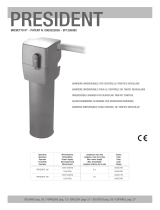 RIB PRESIDENT Benutzerhandbuch
-
Genius Vision Bedienungsanleitung
-
 Beninca DA.BA Operating Instructions Manual
-
 RIB R50 ICE Benutzerhandbuch
-
DEA TRAFIK_N Bedienungsanleitung
-
Marantec PA68 Bedienungsanleitung
-
V2 Elettronica V2 WES-BASE Bedienungsanleitung
-
CAME G6000 Bedienungsanleitung
-
CAME G 6000 Benutzerhandbuch


