Beninca DA.BA Operating Instructions Manual
- Typ
- Operating Instructions Manual

L8542338
Rev. 11/04/04
DA.BA
CENTRALINA A MICROPROCESSORE
CONTROL UNIT WITH MICROCONTROLLER
MIKROCONTROLLER-STEUERUNG
CENTRALE A MICROCONTRÔLEUR
CENTRALITA A MICROPROCESADOR
CENTRALKA Z MIKROPROCESOREM
Libro istruzioni
Operating instructions
Betriebsanleitung
Livret d’instructions
Libro de instrucciones
Książeczka z instrukcjami
UNIONE NAZIONALE COSTRUTTORI
AUTOMATISMI PER CANCELLI, PORTE,
SERRANDE ED AFFINI

3
Dichiarazione CE di conformità Déclaration CE de conformité
EC declaration of conrmity Declaracion CE de conformidad
EG-Konformitatserklarung Deklaracja UE o zgodności
Con la presente dichiariamo che il nostro prodotto
We hereby declare that our product
Hiermit erklaren wir, dass unser Produkt
Nous déclarons par la présente que notre produit
Por la presente declaramos que nuestro producto
Niniejszym oświadczamy że nasz produkt
DA.BA
è conforme alle seguenti disposizioni pertinenti:
complies with the following relevant provisions:
folgenden einschlagigen Bestimmungen entspricht:
correspond aux dispositions pertinentes suivantes:
satisface las disposiciones pertinentes siguientes:
zgodny jest z poniżej wyszczególnionymi rozporządzeniami:
Direttiva sulla compatibilità elettromagnetica (89/336/
CCE, 93/68/CEE)
EMC guidelines (89/336/EEC, 93/68/EEC)
EMV-Richtlinie (89/336/EWG, 93/68/EWG)
Directive EMV (89/336/CCE, 93/68/CEE) (Compatibilité
électromagnétique)
Reglamento de compatibilidad electromagnética (89/336/
MCE, 93/68/MCE)
Wytyczna odnośnie zdolności współdziałania elektromagne-
tycznego (89/336/EWG, 93/68/EWG)
Norme armonizzate applicate in particolare:
Applied harmonized standards, in particular:
Angewendete harmonisierte Normen, insbesondere:
Normes harmonisée utilisées, notamment:
Normas armonizadas utilzadas particularmente:
Normy standard najczęściej stosowane:
EN 55022, EN 61000-3-2, EN 61000-3-3, EN 50082-1
Data/Firma
Direttiva sulla bassa tensione (73/23/CEE, 93/68/CEE)
Low voltage guidelines (73/23/EEC, 93/68/EEC)
Tiefe Spannung Richtlinie (73/23/EWG, 93/68/EWG)
Directive bas voltage (73/23/CEE, 93/68/CEE)
Reglamento de bajo Voltaje (73/23/MCE, 93/68/MCE)
Wytyczna odnośnie niskiego napięcia (73/23/EWG, 93/
68/EWG)
Norme armonizzate applicate in particolare:
Applied harmonized standards, in particular:
Angewendete harmonisierte Normen, insbesondere:
Normes harmonisée utilisées, notamment:
Normas armonizadas utilzadas particularmente:
Normy standard najczęściej stosowane:
EN 60204-1, EN 60335-1
Data/Firma
Automatismi Benincà Srl
Via Capitello, 45
36066 Sandrigo (VI)
ITALIA

3
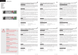
ON
Display
ON
ON
Ricevitore
radio
Caricabatteria
Antenna
Lampeggiante 24V
Spia Barriera
aperta 24V
Chiude
Apre
P.P.
STOP
Finecorsa Chiude
Finecorsa Apre
Fotocellula
Costa Sicurezza
On: Costa elettronica
Off: Costa meccanica
On: Costa assente
Off: Costa presente
On: Fotocellula assente
Off: Fotocellula presente
On: Finec. apertura assente
Off: Finec. apertura presente
On: Finec. chiusura assente
Off: Finec. chiusura presente
On: STOP assente
Off: STOP presente
Batterie
(da collegare
solo con
caricabatteria
inserito)
230Vac Primario
Trasformatore
Secondario
Trasformatore
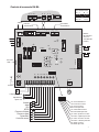
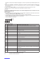
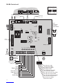
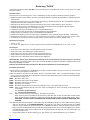
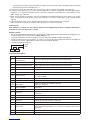
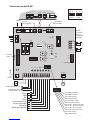
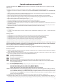
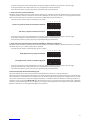
Centrale di comando DA.BA

4
5
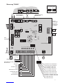
Centrale di comando DA.BA
La centrale a microcontrollore “DA.BA” può essere usata per comandare motori a 24Vdc di potenza non superiore
a 100W.
Caratteristiche:
Questa centrale è adatta al comando di un motore 24Vdc, 100W per la movimentazione di barriere stradali.
• Possibilità di comando tramite pulsanti separati (APRE, CHIUDE, P.P., STOP).
• Predisposizione per il collegamento a fotodispositivi che in caso di oscuramento del raggio infrarosso, determinano
l’inversione del movimento della barriera in fase di chiusura.
• Predisposizione per il collegamento di una costa di sicurezza (meccanica o elettronica) in chiusura.
• Uscita per il collegamento di un lampeggiante e di una spia per la segnalazione della barriera aperta.
• Uscita per il comando di un’elettroserratura a 24V.
• Funzione di richiusura automatica inseribile con durata regolabile.
• Rallentamento tramite necorsa con velocità regolabile mediante programmazione.
• Rilevazione degli ostacoli a sensore amperometrico, a sensibilità regolabile.
• Funzionamento in mancanza di tensione di rete 230V, mediante batterie tampone (utilizzando l’apposito caricabat-
teria).
• Possibilità di collegare no a 7 barriere mediante collegamento seriale utilizzando una sola barriera per il co-
mando.
• Rilevazione del guasto della costa di sicurezza portandosi in funzionamento a uomo presente.
Alimentazione:
• 230Vca, ±10%
• 22÷27Vdc, 12A, forniti da 2 batterie al piombo ermetiche, 12Vdc - 6.5Ah cad. collegate in serie.
Protezioni:
• Contro il cortocircuito della linea di alimentazione generale mediante fusibile
• Contro il cortocircuito delle linee ausiliarie mediante fusibile
• Contro il cortocircuito della linea ad alta tensione mediante fusibile
• Contro le sovratensioni mediante varistore su alta e bassa tensione
• Contro il cortocircuito del motore mediante limitatori elettronici
ATTENZIONE: La protezione contro l’inversione di polarità della batteria è subordinata all’impiego di fusibili di
corretto valore, e comunque genera correnti istantanee pericolose per il circuito e l’operatore. Si raccomanda
la massima attenzione per evitare lo scambio di polarità.
La centrale sprovvista di scheda caricabatteria non funziona inserendo le batterie tampone.
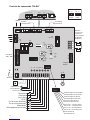
Installazione della centrale
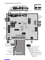
a) Effettuare i collegamenti come dallo schema della gura, ponendo particolare attenzione ai collegamenti dove occorra
osservare la polarità.
b) Escludere tutti gli ingressi normalmente chiusi che non si desidera utilizzare: Stop (25), Fc (26), Fa (27), Ftc (28), Asc
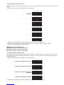
(29) utilizzando i 6 dip-switch vicini alla morsettiera estraibile. Le corrispondenze sono:
DSW1 Simulazione pulsante Stop
DSW2 Simulazione Finecorsa Chiusura
DSW3 Simulazione Finecorsa Apertura
DSW4 Simulazione Fotocellula
DSW5 Simulazione Costa di Sicurezza (Costa presente: Dip5= Off; Costa assente: Dip5= On)
DSW6 Selezione tipo Costa (porre Off il Dip5 e collegare obbligatoriamente un tipo di costa all’ingresso ASC)
Off= Costa Meccanica
On= Costa Elettronica
N.B.: Se non si dispone di alcun tipo di costa porre On il Dip5.
Se si collega la costa meccanica porre Off il Dip5 e Off il Dip6.
Se si collega la costa elettronica porre Off il Dip5 e On il Dip6
Attenzione: Non effettuare ponticelli esterni sugli ingressi non utilizzati.
N.B.: Se la costa rimane attiva per almeno 10 secondi (quindi anche in caso di malfunzionamento), la centrale si porta
in funzionamento “UOMO PRESENTE” cioè per movimentare la barriera si deve tenere premuto il pulsante di
“Apre” per aprire la barriera e “Chiude” per chiudere la barriera. Al rilascio dei pulsanti la barriera si ferma. Il led
PROG resta acceso senza lampeggio. Dopo la disattivazione della costa la centrale ritorna in funzionamento
normale dopo circa 3 sec.
c) Collegare gli ingressi di comando: PP (24), Apre (23), Chiude (22).
d) Collegare l’alimentazione 24Vdc (11,12) ad eventuali dispositivi collegati alla centrale (fotocellule, ricevitori,…) ri-

4
5
spettando la corretta polarità. Collegare il lampeggiante e l’eventuale “spia barriera aperta” SBA (lampade 24V, 3W
max).
e) Dopo aver ricontrollato i collegamenti, alimentare la centrale ai morsetti di ingresso 230Vac (1,2).
All’accensione dovrebbero essere accesi i led sugli ingressi: STOP, FT e almeno uno dei led FC o FA. Il led PROG
deve lampeggiare.
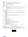
f) Regolare i trimmer LIM-A e LIM-C, che consentono di limitare la corrente massima fornita al motore:
LIM-A: per limitare la corrente in apertura, LIM-C: per limitare la corrente in chiusura.
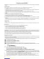
Avvertenze
Per alimentare la centrale con batterie tampone si deve utilizzare obbligatoriamente il caricabatterie da inserire
nell’apposito connettore (J3).
Batterie tampone
• Se si utilizzano delle batterie tampone (2x12V in serie), per togliere completamente l’alimentazione alla centrale è
sufciente scollegare il morsetto “+BATT, -BATT” (33, 34).
• Il caricabatterie necessita di alcuni giorni per fornire una ricarica completa alle batterie.
• Durante il funzionamento a batteria, il motore ha una velocità di marcia leggermente minore rispetto al funzionamento
normale, indipendentemente dal livello di carica delle batterie.
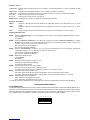
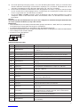
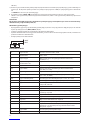
• Corretto collegamento delle batterie.
+ BATT
- BATT
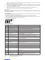
Funzione Ingressi/Uscite
1,2 Ingresso 230Vac Alimentazione centrale 230Vac, 50Hz
3,4 Uscita primario trasformatore Uscita verso il primario del trasformatore 220V/0-18V/0-26Vac
5,6 Ingresso seriale Ingresso comunicazione seriale con più barriere (5= GND; 6= +)
7,8 Ing. second. trasf. 18V Ingresso dal secondario del trasformatore 0-18Vac
9,10 Ing. second. trasf. 26V Ingresso dal secondario del trasformatore 0-26Vac
11,12 Uscita 24Vdc Uscita alimentazione ausiliaria 24Vdc stabilizzati
(11= GND; 12= +24V)
13,14 Uscita 2° canale Contatto N.A. comandato dal secondo canale del radiocomando
15,16 Ingresso antenna Collegamento antenna per scheda ricevente del radiocom. (15= + ant;
16= GND)
17,18 Uscita elettroserratura Morsetti di uscita per l’elettroserratura (17= + ser; 18= - ser)
19,20 Uscita LP1 Morsetti di uscita del lampeggiante. Lampada 24V, 10W max.
21,20 Uscita SBA Morsetti di uscita della “Spia barriera aperta”.
Lampada 24V, 10W max.
22 Ingresso CHIUDE Contatto N.A.
23 Ingresso APRE Contatto N.A.
24 Ingresso P.P. Ingresso Passo-Passo. Collegato in parallelo all’uscita del radiocomando.
Contatto N.A.
25 Ingresso STOP Contatto N.C.
26 Ingresso FC Ingresso necorsa di chiusura. Contatto N.C.
27 Ingresso FA Ingresso necorsa di apertura. Contatto N.C.
28 Ingresso FTC Da collegare al contatto di uscita della fotocellula. Contatto N.C.
29 Ingresso ASC Ingresso per costa o dispositivo di sicurezza il cui intervento provoca
l'inversione di marcia per 1 secondo se il motore è in fase di chiusura.
Contatto N.C.
30 Uscita COM Morsetto comune per tutti gli ingressi.
31,32 Uscita Motore Al motore 24Vdc
33,34,
35,36
Ingresso batteria Collegamento diretto per batteria tampone (2x12V),
(33= +24V; 34,35,36= GND)
J1 Connettore scheda ricevente del radiocomando
J3 Connettore scheda caricabatteria

6
7
Funzione dei Led
+36V (verde) Segnala la presenza della tensione +36V relativa al circuito di potenza; se spento controllare i fusibili
F6, F5.
+24V (verde) Segnala la presenza della tensione +24V; se spento controllare il fusibile F5.
+5V (verde) Segnala la presenza della tensione +5V relativa alla logica; se spento controllare il fusibile F5.
A (verde) Segnala che il motore è in fase di apertura.
C (rosso) Segnala che il motore è in fase di chiusura.
PROG (giallo) Lampeggiante durante il funzionamento normale della centrale.
Funzione dei Trimmer
LIM-A Regola la soglia di intervento del limitatore di coppia del motore in fase di apertura (max. in senso
orario).
LIM-C Regola la soglia di intervento del limitatore di coppia del motore in fase di chiusura (max. in senso
orario).
TCA Regola il tempo di chiusura automatica da 0 secondi a 240 secondi (max. in senso orario).
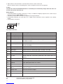
Funzione Dip-Switch S2
DSW1 Funzione “Prelampeggio”: la luce lampeggiante viene attivata 3 secondi prima dell’inizio di ogni manovra
Off: Disabilitata
On: Abilitata
DSW2 Funzione “Chiusura automatica”: per ragioni di sicurezza, la funzione “Chiusura automatica” è sempre
disabilitata a seguito di un comando agli ingressi di “Stop”. Un comando all’ingresso “ASC” non blocca la
funzione “Chiusura automatica” se il motore è fermo.
Off: Chiusura automatica disabilitata
On: Chiusura automatica abilitata
DSW3 Funzione “Condominiale”: l’ingresso “P.P.” non ferma il motore durante la fase di apertura. Ad apertura
completata, l’ingresso “P.P” è abilitato per la chiusura del cancello.
Off: Funzione condominiale disabilitata
On: Funzione condominiale abilitata
DSW4 Abilitazione elettroserratura.
Off: Disabilitata
On: Abilitata
DSW5 Modo di funzionamento per l’ingresso “P.P”.
Off: Sequenza Apre/Stop/Chiude/Stop
On: Sequenza Apre/Chiude
DSW6 Funzione intervento costa in chiusura ASC.
Off: Dopo l’intervento della costa, la barriera inverte.
On: Dopo l’intervento della costa, la barriera inverte per 1 secondo e si ferma.
DSW7 Intervento fotocellula (con Dip2 in On).
Off: Dopo l’intervento della fotocellula, il tempo della chiusura automatica resta invariato.
On: Dopo l’intervento della fotocellula, il tempo della chiusura automatica si riduce a 1 secondo.
DSW8 Modo operativo del lampeggiante
Off: In apertura il lampeggiante si spegne.
On: In apertura il lampeggiante resta acceso.
Le funzioni associate ai Dip-Switch sono attive dopo una manovra completa dalla variazione dei Dip-Switch.
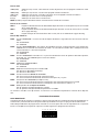
PROGRAMMAZIONE AVANZATA
NOTA IMPORTANTE:
La programmazione delle funzioni avanzate si effettua selezionando una particolare combinazione di Dip-Switch nel se-
lettore S2 e memorizzando la funzione con la pressione del pulsante S3 no allo spegnimento del LED giallo PROG.
Al termine della procedura di programmazione avanzata è necessario riportare i Dip-Switch S2 nella posizione iniziale.
Per semplicare questa operazione, annotare le impostazioni di base nella seguente tabella.

6
7
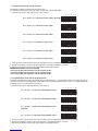
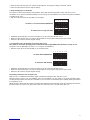
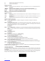
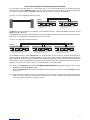
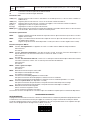
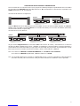
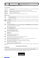
1 - Programmazione della velocità massima
Permette di scegliere la velocità massima del motore.
La velocità del motore può variare dal 100% al 50% della velocità disponibile.
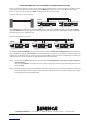
• A motore fermo porre i Dip delle funzioni come in gura:
Se si desidera una velocità massima al 100% (Default)
12345678
12345678
12345678
12345678
12345678
12345678
Se si desidera una velocità massima al 90%
Se si desidera una velocità massima al 80%
Se si desidera una velocità massima al 70%
Se si desidera una velocità massima al 60%
Se si desidera una velocità massima al 50%
• Tenere premuto il pulsante posto vicino al microprocessore; il Led Giallo rimane acceso a luce ssa.
• Quando il Led Giallo si spegne, rilasciare il pulsante. La programmazione è avvenuta.
• Riportare i Dip-Switch nella posizione precedente alla programmazione.
IMPORTANTE: Nelle barriere mod.VE.650
con asta da 6,50m non impostare velocità superiori al 70%
con asta da 6,00m non impostare velocità superiori al 80%
con asta da 5,50m non impostare velocità superiori al 90%
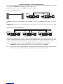
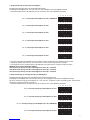
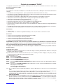
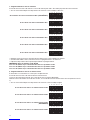
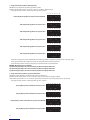
2 - Programmazione della velocità in rallentamento
Permette di scegliere la velocità del motore durante il rallentamento. La velocità del motore può variare dal 10% al
40% della velocità massima disponibile. Utilizzando le velocità di rallentamento di 10% e 20% si consiglia di utilizzare
il rallentamento crescente (funzione avanzata 3).
• A motore fermo porre i Dip delle funzioni come in gura:
12345678
12345678
12345678
12345678
Se si desidera una velocità in rallentamento al 10%
Se si desidera una velocità in rallentamento al 20%
Se si desidera una velocità in rallentamento al 30%
(Default)
Se si desidera una velocità in rallentamento al 40%
• Tenere premuto il pulsante posto vicino al microprocessore; il Led Giallo rimane acceso a luce ssa.
• Quando il Led Giallo si spegne, rilasciare il pulsante. La programmazione è avvenuta.
• Riportare i Dip-Switch nella posizione precedente alla programmazione.

8
9
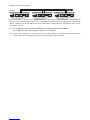
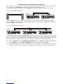
3 - Programmazione del tipo di rallentamento
Permette di scegliere il tipo di rallentamento che la barriera esegue dopo aver trovato il necorsa (sia in apre che in
chiude).
Si può avere un rallentamento costante (Default) oppure crescente, indicato nei casi in cui la barriera in rallentamento
non riesce a chiudersi completamente.
• A motore fermo porre i Dip delle funzioni come in gura:
12345678
12345678
Se si desidera un rallentamento costante (Default)
Se si desidera un rallentamento crescente
• Tenere premuto il pulsante posto vicino al microprocessore; il Led Giallo rimane acceso a luce ssa.
• Quando il Led Giallo si spegne, rilasciare il pulsante. La programmazione è avvenuta.
• Riportare i Dip-Switch nella posizione precedente alla programmazione.
4 - Programmazione del lampeggio della SBA in completa chiusura
Permette di scegliere il modo di funzionamento della Spia barriera aperta (SBA) quando la barriera è completamente
chiusa.
Si può avere l'accensione della SBA ogni 3 secondi oppure lo spegnimento (Default).
• A motore fermo porre i Dip delle funzioni come in gura:
12345678
12345678
Se si desidera a barrierra chiusa,
la SBA lampeggiante
Se si desidera, a barrierra chiusa,
la SBA spenta (Default)
• Tenere premuto il pulsante posto vicino al microprocessore; il Led Giallo rimane acceso a luce ssa.
• Quando il Led Giallo si spegne, rilasciare il pulsante. La programmazione è avvenuta.
• Riportare i Dip-Switch nella posizione precedente alla programmazione.
Posizionamento Camme e Finecorsa di rallentamento
Spostare le camme per determinare l’angolo di rallentamento della barriera in apertura e chiusura.
Può vericarsi un improvviso arresto della barriera in chiusura se la camma del rallentamento in chiusura determina
uno spazio di rallentamento molto ridotto; per eliminare questo effetto, spostare la camma del rallentamento in chiu-
sura in modo tale che lo spazio di rallentamento in chiusura aumenti permettendo alla barriera di completare il proprio
ciclo di lavoro.
Ritoccare i trimmer LIM-A e LIM-C no ad ottenere l’intervento del limitatore di corrente sia in completa apertura che
in completa chiusura; l’intervento del limitatore è evidenziato dallo spegnimento del led verde A in apertura e del led
rosso C in chiusura.
COLLEGAMENTO DI PIÙ BARRIERE SINCRONIZZATE
Per sincronizzare due o più barriere (no a 7), si deve porre la barriera principale (quella alla quale sono connessi i
comandi) come Master posizionando il Dip-Switch S5 su “M” (a sinistra).
Le altre barriere si devono porre come Slave, posizionando S5 su “S” (a destra).
Collegamento di due barriere contrapposte:
La barriera Master funziona indipendentemente dalle Slave, viceversa le barriere Slave dipendono dalla Master.
Alla barriera Master devono essere collegati i comandi di ingresso e gli eventuali accessori (fotocellule, elettroserratura,
costa, ricevitore radio).

8
9
Collegamento di tre (o più) barriere:
Sulle barriere Slave si devono montare obbligatoriamente solo i necorsa ed eventualmente, se desiderato, gli
ingressi P.P., Apre, Chiude, STOP, FOTOC e Costa, il caricabatteria, l'elettroserratura, il lampeggiante e la spia barriera
aperta e si deve porre in ON i Dip-Switch vicini alla morsettiera per escludere gli ingressi normalmente chiusi (1 STOP,
4 Fotocellula, 5 Costa).
N.B.: Se nella Master si utilizza la Chiusura Automatica, nelle Slave non deve essere abilitata.
Se nella Master si utilizza il prelampeggio, abilitarlo anche nella Slave.
N.B.: Utilizzare per il collegamento cavo schermato 2x1mm2 e tenere separati i cavi di potenza da quelli di comando
e della comunicazione seriale per evitare interferenze, utilizzando 2 guaine separate.

10
11
ON
Display
ON
ON
Antenna
Blinker 24V
Barrier Open
Light 24V
230Vac Transformer
Primary circuit
Transformer
Secondary circuit
Radio
receiver
Close
Open
Step-by-Step
STOP
Close limit stop
Open limit stop
Photocell
Safety edge
On: Electronic edge
Off: Mechanical edge
On: Edge not installed
Off: Edge installed
On: Photocell not installed
Off: Photocell installed
On: Open limit stop not installed
Off: Open limit stop installed
On: Close limit stop not installed
Off: Close limit stop installed
On: STOP not installed
Off: STOP installed
Battery charger
Battery
(connect only
with battery
charger hooked
up)
DA.BA Control unit

10
11
DA.BA Control unit
The “DA.BA” microcontroller control unit can be used with 24Vdc motors having a power no higher than 100W.
Characteristics:
This control unit is designed to operate a 24Vdc, 100W motor for actuating road barriers.
• Controls can be given separate pushbuttons (i.e. APRE-OPEN, CHIUDE-CLOSE, P.P.-STEP BY STEP, STOP).
• Designed to receive photocells so that when the infrared beam is interrupted during the close cycle the barrier
changes direction.
• Designed to receive a safety edge (mechanical or electronic) in close cycle.
• Output for a beacon and a Barrier Open Light signal.
• Output to operate a 24V electrolock.
• Automatic close function with adjustable delay.
• Limit stop slowdown with programmable speed adjustment.
• Amperometric obstacle detector with adjustable sensitivity.
• Operation with buffer batteries during mains power cuts (using the special battery charger).
• 7 barriers can be connected in series as slaves using just one master barrier.
• Safety edge fault detector transfers operation to manned mode.
Power Supply:
• 230Vac, ±10%
• 22÷27Vdc, 12A, supplied by 2 sealed lead batteries, 12Vdc - 6.5Ah each connected in series.
Safeties:
• Overload fuse on main power supply
• Overload fuse on auxiliary lines
• Overload fuse on high voltage line
• Converter against peak voltages on high and low voltage
• Electronic overload limiter on motor
ATTENTION: The protection against inverting the battery poles is only effective if the correct fuses are used.
Surge currents are nevertheless generated, being hazardous for both circuit and operator. Special care must
be taken in ensuring the correct poles are respected.
If the control unit is not tted with a battery charger board it will not operate with buffer batteries.
Installation instructions.
a) Wire according to wiring diagram in the gure, paying special care in ensuring the correct poles are respected.
b) Inhibit all normally closed inputs that are not required: Stop (25), Fc (26), Fa (27), Ftc (28), Asc (29) using the 6 dip-
switches next to the removable terminal block. Their related functions are:
DSW1 Stop push button test
DSW2 Close limit stop test
DSW3 Open limit stop test
DSW4 Photocell test
DSW5 Safety edge test (With safety edge: Dip5= Off; without safety edge: Dip5= On)
DSW6 Select edge type (set Dip5 to Off and one type of edge MUST be connected to the ASC input)
Off= Mechanical safety edge
On= Electronic safety edge
N.B.: If no kind of edge is installed set dip 5 to ON.
If a mechanical edge is connected set dip 5 to OFF and dip 6 to OFF.
If an electronic edge is connected set dip 5 to OFF and dip 6 to ON.
ATTENTION: DO NOT FIT EXTERNAL JUMPERS ON UNUSED INPUTS.
N.B.: If the edge remains armed for at least 10 seconds (therefore also in the event of malfunction), the control unit will
enter the “HOD TO RUN” operating mode, i.e. to action the barrier hold down the APRE (OPEN) pushbutton to
open the barrier and the CHIUDE (CLOSE) pushbutton to close the barrier. When the pushbuttons are released
the barrier will stop. The PROG LED will light up without blinking. After the edge is disactivated, the control unit
returns to normal operation after about 3 sec.
c) Connect the control inputs: PP “Step by Step” (24), Apre “Open” (23), Chiude “Close” (22).
d) Connect the 24Vdc supply (11,12) to any accessories connected to the control unit (e.g. photocells, receivers, etc)
respecting the correct poles. Connect the beacon and any “Barrier Open Light” SBA (24V lamp, max 3W).
e) After having checked the connections, power the control unit at the 230Vac input terminals (1,2).
When powered, the Input LED’s should light up: STOP, FT and at least one of the FC or FA LED’s.
The PROG LED should blink.

12
13
f) Adjust trimmers LIM-A and LIM-C, which limit the maximum current to the motor.
LIM-A to regulate current in the opening phase, LIM-C to regulate current in the closing phase.
Caution
To power the control unit with buffer batteries it is mandatory to use the battery charger which has to be con-
nected to the special connector (J3).
Buffer batteries
• If the buffer batteries are being used (2x12V in series), to shutdown completely all power to the control unit just
disconnect terminal “+BATT, -BATT” (33, 34).
• The battery charger needs a few days to completely recharge the batteries.
• During battery operation, the motor will run at a slightly slower speed than normal, regardless of the battery
charge.
• Correct battery connections:
+ BATT
- BATT
Input/Output functions
1,2 Input 230Vac Power supply of the control unit 230Vac, 50Hz
3,4 Primary output Output to primary circuit of transformer 220V/ 0-18V/0-26Vac
5,6 Serial input Input of serial communication with various road barriers (5=GND; 6=+)
7,8 Secondary 18V input Input from secondary circuit of transformer 0-18Vac
9,10 Secondary 26V input I Input from secondary circuit of transformer 0-26Vac
11,12 24Vdc output Stabilised 24Vdc output for auxiliary power supply
(11= GND; 12=+24V)
13,14 Channel 2 output N.O. contact actuated by second channel of radio control
15,16 Antenna Input Antenna connection for radio control receiver board
(15=+ant; 16=GND))
17,18 Electrolock output Output terminals for electrolock (17=+ser; 18=-ser)
19,20 LP1 output Output terminals for beacon. 24V lamp - max 10W
21,20 SBA output Output terminals for “Barrier Open Light”. 24V lamp - max. 10W.
22 Input CHIUDE (CLOSE) N.O. contact
23 Input APRE (OPEN) N.O. contact
24 P.P. input Step by Step input. Connected in parallel with radio control output. N.O.
contact
25 Input STOP N.C. contact
26 Input FC Input, closing limit switch. N.C. contact
27 Input FA Input, opening limit switch. N.C. contact
28 Input FTC For connection to photocell output contact. N.C. contact.
29 Input for safety edge or
device.
When it trips the motor changes direction for 1 second if it is in the close
cycle. N.C. contact.
30 Output COM Common terminal for all inputs.
31,32 Output Motor To the motor, 24Vdc
33,34
35,36
Input battery Direct connection for buffer battery (2x12V), (33= +24V; 34,35,36= GND)
J1 Connector for radio control receiver board
J3 Connector for battery charger board

12
13
LED functions
+36V (green) Power on signal for +36V power circuit; if it does not light up check fuses F6, F5.
+24V (green) Power on signal for +24V circuit; if it does not light up check fuse F5.
+5V (green) Power on signal for +5V logic circuit. If it does not light up check fuse F5.
A (green) Signals motor is in open cycle.
C (red) Signals that motor is in close cycle.
PROG (yellow) Blinking during normal operation of control unit.
Trimmer functions
LIM-A It regulates the intervention threshold of the torque regulator of the motor in the opening phase (max
in clockwise direction).
LIM-C It regulates the intervention threshold of the torque regulator of the motor in the closing phase (max in
clockwise direction).
TCA It regulates the automatic closing time from 0 to 240 seconds (max in clockwise direction).
Dip-switch functions S2
DSW1 Function “Forewarning”: the ashing light is activated 3 seconds before the beginning of each operation.
Off= Disabled
On= Enabled
DSW2 “Automatic close” function: for safety reasons the “Automatic Close” function is always disabled after a signal
is given to the “STOP” inputs. A signal to the “ASC” input will not interrupt the “Automatic Close” function if
the motor is off.
Off= Disabled
On= Enabled
DSW3 “Condominium” Function: the “P.P.” input will not stop the motor during the open cycle. When the open
cycle is completed, the “P.P.” input is enabled to close the barrier.
Off= Disabled
On= Enabled
DSW4 Electric lock enabled
Off= Disabled
On= Enabled
DSW5 Operating mode for the “P.P.” input.
Off= Open/Stop/Close/Stop sequence
On= Open/Close sequence
DSW6 ASC edge trips in close cycle
Off= When edge trips the barrier changes direction.
On= When edge trips the barrier changes direction for 1 sec. and stops.
DSW7 Photocell trips (Dip2 set to ON)
Off= When photocell trips the automatic close delay remains unchanged.
On= When photocell trips the automatic close delay is shortened to 1 sec.
DSW8 Beacon operating mode
Off= During open cycle the beacon goes out.
On= During open cycle the beacon keeps ashing.
The functions linked with dip-switches are active after a full operation from the change in dip-switch settings.
ADVANCED PROGRAMMING
IMPORTANT NOTE:
To program the advanced functions, a special Dip-Switch combination should be provided for selector switch S2. The
function should then be stored in memory by pressing button S3 until the yellow PROG LED switches off.
At completion of the advanced programming procedure, the Dip-Switches S2 should be moved to the original position.
To facilitate this operation, take note of the basic settings in the following table.

14
15
1 -Programming the maximum speed
This allows to select the maximum speed of the motor. The motor speed can vary from 100% to 50% of the rated
speed.
• With the motor off set the function dips as in the gure below:
To obtain a maximum speed of 100%
(DEFAULT)
12345678
12345678
12345678
12345678
12345678
12345678
To obtain a maximum speed of 90%
To obtain a maximum speed of 80%
To obtain a maximum speed of 70%
To obtain a maximum speed of 60%
To obtain a maximum speed of 50%
• Hold down the pushbutton next to the microprocessor; the YELLOW LED will stay on.
• When the YELLOW LED goes out, release the pushbutton. The program settings have been stored.
• Return the dip-switches to their original settings
IMPORTANT: For mod.VE.650 barriers
with 6.50 m rod never set the speed over 70%
with 6.00 m rod never set the speed over 80%
with 5.50 m rod never set the speed over 90%
2 - Programming the slowdown speed
This allows to select the speed of the motor during slowdown. The motor speed can vary from 10% to 40% of its
rated speed. When using a slowdown speed of 10% and 20% it is best to opt for the increasing slowdown setting
(advanced function 3).
• With the motor off set the function dips as in the gure below:
12345678
12345678
12345678
12345678
To obtain a slowdown speed of 10%
To obtain a slowdown speed of 20%
To obtain a slowdown speed of 30%
(DEFAULT)
To obtain a slowdown speed of 40%
• Hold down the pushbutton next to the microprocessor; the YELLOW LED will stay on.

14
15
• When the YELLOW LED goes out, release the pushbutton. The program settings have been stored.
• Return the dip-switches to their original settings
3 -Programming type of slowdown
This allows to select how the barrier will slowdown after it trips the limit stop (both in open and close cycles).
The options are a constant slowdown (DEFAULT) or increasing, recommended in cases where the barrier in slowdown
is unable to fully close.
• With the motor off set the function dips as in the gure:
12345678
12345678
To obtain a constant slowdown (DEFAULT)
To obtain an increasing slowdown
• Hold down the pushbutton next to the microprocessor; the YELLOW LED will stay on.
• When the YELLOW LED goes out, release the pushbutton. The program settings have been stored.
• Return the dip-switches to their original settings
4 - Programming the sba ashing mode when fully closed
This allows to select the operating mode of the Barrier Open Light (SBA) when the barrier is fully closed.
The options are: the SBA lights up every 3 sec. or it goes out (DEFAULT).
• With the motor off set the function dips as in the gure below:
12345678
12345678
To obtain the SBA ashing
To obtain SBA off (DEFAULT)
• Hold down the pushbutton next to the microprocessor; the YELLOW LED will stay on.
• When the YELLOW LED goes out, release the pushbutton. The program settings have been stored.
• Return the dip-switches to their original settings
Positioning slowdown cams and limit stop
Shift the cams to calibrate the slowdown angle of the barrier during the open and close cycles.
When the barrier closes it may stop suddenly if the close slowdown cam only allows a very tight slowdown space.
To eliminate this problem shift the close slowdown cam to increase the slowdown space thereby allowing the barrier
to complete its cycle.
Adjust trimmers LIM-A and LIM-C until the current limiter trips both when the barrier is fully open and fully closed: when
the limiter trips in the open cycle green LED A goes out and in the close cycle red LED C goes out.

16
17
CONNECTING SEVERAL SYNCHRONISED BARRIERS
For a synchronized operation of two or more road barriers (up to 7) a main barrier has to be designated (i.e. connected
to the controls) as MASTER by setting dip-switch S5 to “M” (to left).
The other barriers have to become SLAVES by setting S5 to “S” (to right).
To connect two opposite barriers:
The Master barrier operates independently from the Slaves and vice-versa the Slave barriers depend on the Mas-
ter.
The Master barriers must be connected to the input controls and any accessories (e.g. photocells, electrolock, edge,
radio receiver).
To connect three (or more) road barriers:
The Slave barriers MUST only have the limit switches and only if required, inputs STEP BY STEP, OPEN, CLOSE, STOP,
PHOTOC. and EDGE, the battery charger, electrolock, beacon and Barrier Open Light and the dip-switches next to the
terminal block have to be set to ON to inhibit the normally closed inputs (i.e. 1 STOP, 4 PHOTOCELL, 5 EDGE).
N.B.: If the MASTER is programmed with AUTOMATIC CLOSE, the SLAVES must not be enabled. If
the MASTER is programmed with Warning, it also has to be programmed on the SLAVES
N.B.: It is best to use a 2x1mm shielded cable for connections and always keep the power cables separate from the
control and serial communication cabling to avoid interference, using 2 individual conduits.

16
17
ON
Display
ON
ON
Funk
empfänger
Batterieladegerät
Antenne
Blinkleuchte 24V
Kontrollampe für offene
Schranke 24V
Schließen
Öffnen
Schrittschaltung
STOP
Endschalter schließen
Endschalter öffnen
Lichtschranke
Sicherheitsleiste
On: Elektronische Kontaktleiste
Off: Mechanische Kontaktleiste
On: Kontaktleiste abwesend
Off: Kontaktleiste anwesend
On: Lichtschranke abwesend
Off: Lichtschranke anwesend
On: Endsch. Offnen abwesend
Off: Endsch. Offnen anwesend
On: Endsch. Schließen abwesend
Off: Endsch. Schließen anwesend
On: STOP abwesend
Off: STOP anwesend
Batterien
(nur bei einge-
setztem Bat-
terieladegerät
anschließen)
230Vac Primärwicklung
Transformator
Sekundärwicklung
Transformator
Steuerung ”DA.BA”

18
19
Steuerung ”DA.BA”
Die Zentrale mit Microcontroller “DA.BA” kann zur Steuerung von 24Vdc Motoren mit einer Leistung von max. 100W
eingesetzt werden.
Charakteristiken:
Diese Zentrale ist zur Steuerung eines 24Vcc, 100W Motors für den Antrieb von Straßenschranken geeignet.
• Möglichkeit der Steuerung mittels separater Tasten (APRE-ÖFFNEN, CHIUDE-SCHLIESSEN, P.P-SCHRITT-SCHAL-
TUNG, STOP).
• Vorbereitung für den Anschluss an Photozellen-Vorrichtungen, die bei Unterbrechen des Infrarotbündels die Bewe-
gung der Schranke in der Schließphase umkehren.
• Vorbereitung für den Anschluss einer Sicherheitsleiste (mechanisch oder elektronisch) am Verschluss.
• Ausgang für den Anschluss einer Blinkleuchte und einer Kontrollleuchte als Anzeige für offene Schranke.
• Ausgang für die Steuerung eines 24V Elektroschlosses.
• Funktion für automatischen Wiederverschluss mit einstellbarer Dauer.
• Verlangsamung mittels Endschalter mit programmierbarer Geschwindigkeit.
• Hinderniserfassung mit Stromsensor mit verstellbarer Empndlichkeit.
• Betrieb bei Netzspannungsausfall 230V mittels Pufferbatterien (unter Verwendung des speziellen Ladegerätes).
• Möglichkeit des Anschlusses von bis zu 7 seriell angeschlossenen Schranken, wobei nur eine Schranke gesteuert wird.
• Feststellung des Defekts der Sicherheitsleiste, wobei sich die Zentrale auf Totmann-Betrieb stellt.
Spannungsversorgung:
• 230Vca, ±10%
• 22÷27Vdc, 12A, geliefert von 2 in Serie angeschlossenen hermetischen Bleibatterien mit je 12Vdc - 6.5Ah.
Sicherungen:
• Gegen Kurzschluss der Haupt-Versorgungsleitung mittels Sicherung
• Gegen Kurzschluss der Hilfsleitungen mittels Sicherung
• Gegen Kurzschluss der Hochspannungsleitung mittels Sicherung
• Gegen Überspannungen mittels Hoch- und Niederspannungsregler
• Gegen Kurzschluss des Motors mittels elektronischer Begrenzer
ACHTUNG! Der Schutz gegen Polumkehr der Batterie ist von der Verwendung von Sicherungen des korrekten
Werts abhängig und erzeugt in jedem Fall für den Kreis und die Bedienungsperson gefährliche Augenblickströme. Die
Umpolung unbedingt vermeiden.
Zentralen ohne Batterieladekarte können bei Einsatz der Pufferbatterien nicht funktionieren.
Installation der Zentrale
a) Die Anschlüsse gemäß Schema der Abbildung herstellen, wobei besonders auf jene Anschlüsse zu achten ist, bei
denen die Polung eingehalten werden muss.
b) Alle normalerweise geschlossene Eingänge, die nicht verwendet werden sollen, ausschließen: Stop(25), Fc(26),
Fa(27), Ftc(28), Asc(29) wofür die 6 Dip-Switches in der Nähe der abnehmbaren Klemmenleiste verwendet werden.
Die Übereinstimmungen sind:
DSW1 Simulation Stop Taste
DSW2 Simulation Endschalter zum Schließen
DSW3 Simulation Endschalter zum Öffnen
DSW4 Simulation Lichtschranke
DSW5 Simulation Sicherheitsleiste (Leiste anwesend: DIP5=OFF; Leiste abwesend: DIP5=ON)
DSW6 Wahl Typ Kontaktleiste (den Dip 5 auf OFF stellen und obligatorisch einen Leistentyp an den Eingang ASC
anschließen)
Off= mechanische Kontaktleiste
On= elektronische Kontaktleiste
N.B.: Wenn keinerlei Leistentyp vorhanden ist, den Dip5 auf ON stellen.
Wenn die mechanische Kontaktleiste angeschlossen wird, den Dip5 auf OFF und den Dip6 auf OFF stellen.
Wenn die elektronische Kontaktleiste angeschlossen wird, den Dip5 auf OFF und den Dip6 auf ON stellen.
ACHTUNG: AN DEN NICHT VERWENDETEN EINGÄNGEN KEINE EXTERNEN BRÜCKEN HER-
STELLEN.
N.B.: Wenn die Kontaktleiste wenigstens 10 Sekunden lang aktiv bleibt (das heißt also auch im Fall der Funktionsstörung),
stellt sich die Zentrale auf “TOTMANN-BETRIEB”, das heißt dass zum Öffnen der Schranke die Taste „Apre“
(Öffnen), und zum Schließen der Schranke die Taste „Chiude“ (Schließen) gedrückt gehalten werden müssen.
Beim Loslassen der betreffenden Taste hält die Bewegung der Schranke an. Die LED PROG blinkt nicht, sondern
ist bleibend eingeschaltet. Nach Deaktivierung der Kontaktleiste kehrt die Zentrale nach zirka 3 Sekunden zum
normalen Betrieb zurück.
c) Die Steuereingänge: PP (Schrittschaltung) (24), Apre (Öffnen) (23), Chiude (Schließen) (22) anschließen.

18
19
d) Die 24Vdc Spannungsversorgung 24Vdc (11,12) unter Einhaltung der korrekten Polung an eventuell mit der
Zentrale verbundene Vorrichtungen (Lichtschranken, Empfänger, usw.) anschließen. Die Blinkleuchte und die
eventuelle „Kontrolllampe für offene Schranke” SBA (Lampe 24V - 3W max.) anschließen.
e) Die Anschlüsse kontrollieren und die Zentrale an den Eingangsklemmen 230Vac (1,2) speisen. Beim Einschalten
müssen auch die LEDs an den Eingängen STOP, FT eingeschaltet sein und wenigstens eine der LEDs FC oder
FA muss eingeschaltet sein. Die LED PROG muss blinken.
f) Die Trimmer LIM-A und LIM-C einstellen, welche die Begrenzung des dem Motor gelieferten max. Stroms
ermöglichen. LIM-A: um den Strom beim Öffnen zu beschränken, LIM-C: um den Strom beim Schließen zu
beschränken.
Hinweise
Um die Zentrale über die Pufferbatterien zu speisen, muss obligatorisch das Batterialadegerät benutzt werden,
das an den speziellen Verbinder (J3) angeschlossen wird.
Pufferbatterie
• Falls Pufferbatterien (2x12V in Reihe) verwendet werden, genügt es, die Klemme “+BATT, -BATT” (33,34) abzuhängen,
um die Spannungsversorgung der Zentrale ganz zu unterbrechen.
• Das Batterieladegerät benötigt zum vollständigen Laden der Batterien einige Tage.
• Während des Batteriebetriebs ist die Ganggeschwindigkeit des Motors unabhängig vom Ladezustand der Batterien
etwas niedriger als bei normalem Betrieb.
• Korrekter Anschluss der Batterien:
+ BATT
- BATT
Funktion Eingaben/Ausgaben
1,2 Eingang 230Vac Speisung der Zentrale 230Vac, 50Hz
3,4 Ausgang Primärwicklung Trafo Ausgang zur Primärwicklung des Transformators 220V/ 0-18V/0-26Vac
5,6 Serieller Eingang Eingang serielle Kommunikation mit mehreren Schranken
(5= GND; 6= +)
7,8 Eing. Sekundärwicklung Trafo 18V Eingang von der Sekundärwicklung des Transformators 0-18Vac
9,10 Eing. Sekundärwicklung Trafo 26V Eingang von der Sekundärwicklung des Transformators 0-26Vac
11,12 Ausgang 24Vdc Ausgang Hilfseinspeisung 24Vdc stab. (11= GND; 12=+24V)
13,14 Ausgang 2. Kanal Arbeitskontakt, vom 2. Kanal der Funksteuerung gesteuert
15,16 Eingang Antenne Antennenanschluss für Empfangsplatine der Funksteuerung. (15=+Ant;
16=GND)
17,18 Ausgang Elektroschloss Ausgangsklemmen für Elektroschloss (17=+Schloss; 18=-Schloss)
19,20 Ausgang LP1 Ausgangsklemmen der Blinkleuchte. Lampe 24V - 10W max.
21,20 Ausgang SBA Ausgangsklemmen der “Kontrolllampe für offene Schranke”.
Lampe 24V - 10W max.
22 Eingang SCHLIESSEN Arbeitskontakt
23 Eingang ÖFFNEN Arbeitskontakt
24 Eingang P.P. Eingang Schrittschaltung. Parallel geschaltet mit dem Ausgang der
Funksteuerung. Arbeitskontakt
25 Eingang STOP Ruhekontakt
26 Eingang FC Eingang Endschalter für Schließen. Ruhekontakt
27 Eingang FA Eingang Endschalter für Öffnen. Ruhekontakt
28 Eingang FTC Mit dem Ausgangskontakt der Lichtschranke zu verbinden.
Ruhekontakt
29 Eingang ASC
Eingang für Kontaktleiste oder Sicherheitsvorrichtung, deren Auslösen
die Gangumkehr für 1 Sekunde verursacht, wenn sich der Motor in
Schließphase bendet. Ruhekontakt
30 Ausgang COM Gemeinsame Klemme für alle Eingänge.
31,32 Ausgang Motor Zum Motor 24Vdc
33,34
35,36 Eingang Batterie Direkter Anschluss für Pufferbatterie (2x12V), (33= +24V;
34,35,36=GND)

20
21
J1 Verbinder Empfangsplatine der Funksteuerung
J3 Verbinder Batterieladekarte
Funktion der Leuchte
+36V (grün) Meldet die Präsenz der Spannung +36V des Leistungskreises; wenn aus, die Sicherungen F6, F5
kontrollieren.
+24V (grün) Meldet die Präsenz der Spannung +24V; wenn aus, die Sicherung F5 kontrollieren.
+5V (grün) Meldet die Präsenz der Spannung +5V der Logik, wenn aus, die Sicherung F5 kontrollieren.
A (grün) Meldet, dass sich der Motor in Öffnungsphase bendet.
C (rot) Meldet, dass sich der Motor in Schließphase bendet.
PROG (gelb) Blinkend während des normalen Betriebs der Zentrale.
Funktion der Trimmer
LIM-A Regelt die Schwelle des Drehmomentbegrenzers des Motors während der Öffnungsphase (max. im
Uhrzeigersinn).
LIM-C Regelt die Schwelle des Drehmomentbegrenzers des Motors während der Schließphase (max. im
Uhrzeigersinn).
TCA Regelt die Zeit des automatischen Verschlusses von 0 Sek bis 240 Sek (max. im Uhrzeigersinn).
Funktion der Dip-Drucktasten S2
DSW1 FFunktion “Vorwarnblinken”: das Blinken erfolgt jeweils 3 Sekunden vor Beginn eines Manövers.
Off= Deaktiviert
On= Aktiviert
DSW2 Funktion “Automatikverschluss. Aus Gründen der Sicherheit ist die Funktion “Automatikverschluss” nach
einem Befehl an die Eingänge für “STOP” immer deaktiviert. Ein Befehl an den Eingang “ASC” blockiert die
Funktion “Automatikverschluss” nicht, wenn der Motor stillsteht.
Off= Deaktiviert
On= Aktiviert
DSW3 Funktion “Mehrbenutzer”: der Eingang “P.P.” (Schrittschaltung) hält den Motor während der Öffnungsphase
nicht an. Nach dem kompletten Öffnen ist der Eingang “P.P.” (Schrittschaltung) für das Schließen der Schranke
aktiviert.
Off= Deaktiviert
On= Aktiviert
DSW4 Freigabe Elektroschloss
Off= Deaktiviert
On= Aktiviert
DSW5 Betriebsmodus für Eingang “P.P” (Schrittschaltung).
Off= Reihenfolge Öffnen/Stop/Schließen/Stop
On= Reihenfolge Öffnen/Schließen
DSW6 Auslösefunktion Kontaktleiste in Verschluss ASC
Off= Nach Auslösen der Kontaktleiste wird die Schranke invertiert.
On= Nach Auslösen der Kontaktleiste wird die Schranke 1 Sek. invertiert und hält an.
DSW7 Auslösen Lichtschranke (bei Dip2 auf ON)
Off= Nach Auslösen der Lichtschranke bleibt die Zeit des automatischen Verschlusses unverändert.
On= Nach Auslösen der Lichtschranke wird die Zeit des automatischen Verschlusses um 1 Sek. verringert.
DSW8 Betriebsart der Blinkleuchte
Off= Beim Öffnen verlöscht die Blinkleuchte.
On= Beim Öffnen bleibt die Blinkleuchte eingeschaltet.
Die den Dip-Switches zugeordneten Funktionen werden aktiv, nachdem nach der Veränderung ihrer Einstellung ein
komplettes Manöver durchgeführt wurde.
WEITERFÜHRENDE PROGRAMMIERUNG
WICHTIGE ANMERKUNG:
Die Programmierung der fortgeschrittenen Funktionen erfolgt durch eine besondere Kombination der Dip-Schalter
des Wählers S2 und durch die Speicherung der Funktion indem die Taste S3 gedrückt wird bis die gelbe LEUCHTE
PROG erlischt.
Am Ende der Prozedur für die fortgeschrittene Programmierung, die Dip-Schalter S2 wieder in die Ausgangsposition
bringen. Um den Vorgang zu vereinfachen, die Ausgangspositionen in nachstehender Tabelle notieren.
Seite wird geladen ...
Seite wird geladen ...
Seite wird geladen ...
Seite wird geladen ...
Seite wird geladen ...
Seite wird geladen ...
Seite wird geladen ...
Seite wird geladen ...
Seite wird geladen ...
Seite wird geladen ...
Seite wird geladen ...
Seite wird geladen ...
Seite wird geladen ...
Seite wird geladen ...
Seite wird geladen ...
Seite wird geladen ...
Seite wird geladen ...
Seite wird geladen ...
Seite wird geladen ...
Seite wird geladen ...
Seite wird geladen ...
Seite wird geladen ...
Seite wird geladen ...
Seite wird geladen ...
-
 1
1
-
 2
2
-
 3
3
-
 4
4
-
 5
5
-
 6
6
-
 7
7
-
 8
8
-
 9
9
-
 10
10
-
 11
11
-
 12
12
-
 13
13
-
 14
14
-
 15
15
-
 16
16
-
 17
17
-
 18
18
-
 19
19
-
 20
20
-
 21
21
-
 22
22
-
 23
23
-
 24
24
-
 25
25
-
 26
26
-
 27
27
-
 28
28
-
 29
29
-
 30
30
-
 31
31
-
 32
32
-
 33
33
-
 34
34
-
 35
35
-
 36
36
-
 37
37
-
 38
38
-
 39
39
-
 40
40
-
 41
41
-
 42
42
-
 43
43
-
 44
44


Beninca DA.BA Operating Instructions Manual
- Typ
- Operating Instructions Manual
in anderen Sprachen
- français: Beninca DA.BA
- español: Beninca DA.BA
- polski: Beninca DA.BA
Verwandte Artikel


Andere Dokumente
-
Aprimatic PTR-24 Electrical Installation, Use And Maintenance Instructions
-
Marantec CBX10224 Bedienungsanleitung
-
Vimar EBR2 Installationsanleitung
-
Genius JA466 Bedienungsanleitung
-
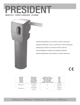 RIB PRESIDENT Benutzerhandbuch
-
PRESIDENT EP1295992 Installation Instructions Manual
-
-
Viessmann 5104 Bedienungsanleitung
-
 Thorn Voyager Style / VOYAGER STYLE 150 MS-WF15 ECS SM-S WH Installationsanleitung

