Hitachi CP2155TA Benutzerhandbuch
- Kategorie
- LCD-Fernseher
- Typ
- Benutzerhandbuch

DECEMBER 1999
No. 0104
CP2155TA
SERVICE MANUAL
WARTUNGSHANDBUCH
CAUTION CAUTION ::
Before servicing this chassis, it is important that the service technician read
the “Safety Precautions” and “Product Safety Notices” in this service manual.
VORSICHT :VORSICHT :
Vor Öffnen des Gehäuses hat der Service-Ingenieur die „Sicherheitshinweise“
und „Hinweise zur Produktsicherheit“ in diesem Wartungshandbuch zu lesen.
Data contained within this Service
manual is subject to alteration for
improvement.
Die in diesem Wartungshandbuch
enthaltenen Spezifikationen können
sich zwecks Verbesserungen
ändern.

1
ENGLISH..............................................................................................................................................................2
SAFETY ...........................................................................................................................................................2
SAFETY PRECAUTIONS.............................................................................................................................................2
SAFETY AND ISOLATION..........................................................................................................................................3
USER GUIDE ..................................................................................................................................................4
OPERATING INSTRUCTIONS.....................................................................................................................................4
CIRCUIT DESCRIPTION.................................................................................................................................6
SWITCHED MODE POWER SUPPLY..........................................................................................................................6
TUNER and IF STAGES................................................................................................................................................7
SOURCE SELECTION..................................................................................................................................................8
COLOUR DECODER....................................................................................................................................................9
HORIZONTAL and VERTICAL DEFLECTION..........................................................................................................10
TUBE-BASE PANEL...................................................................................................................................................11
AUDIO DEMODULATION AND POWER AMPLIFIER.............................................................................................12
REMOTE CONTROL..................................................................................................................................................13
MICROPROCESSOR CONTROL SYSTEM................................................................................................................14
SERVICEING.................................................................................................................................................15
ADJUSTMENTS .........................................................................................................................................................15
DEUTSCH........................................................................................................................................................17
SICHERHEIT.................................................................................................................................................17
SICHERHEITSVORKEHRUNGEN.............................................................................................................................17
SICHERHEIT UND ISOLIERUNG..............................................................................................................................18
BEDIENUNGSANLEITUNG ..........................................................................................................................19
BETRIEBSVORSCHRIFTEN......................................................................................................................................19
SCHALTUNGSBESCHREIBUNG...................................................................................................................21
SCHALTMODUS STROMVERSORGUNG ................................................................................................................21
TUNER und ZF-STUFEN............................................................................................................................................23
QUELLEN-AUSWAHL...............................................................................................................................................24
FARBDECODER.........................................................................................................................................................25
HORIZONTALE UND VERTIKALE DEFLECTION...................................................................................................26
Die CRT-Trägerplatte...................................................................................................................................................27
AUDIO DEMODULATION UND LEISTUNGSVERSTÄRKER..................................................................................28
FERNSTEUERUNG....................................................................................................................................................29
MICROCONTROLLER STEUERUNGSSYSTEM.......................................................................................................30
WARTUNG ....................................................................................................................................................31
EINSTELLUNGEN......................................................................................................................................................31
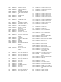
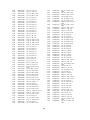
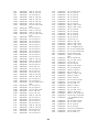
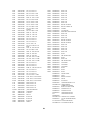
PARTS LIST / STÜCKLISTE...........................................................................................................................33

2
EnglEnglishsh
SAFETYSAFETY
SAFETY PRECAUTIONSSAFETY PRECAUTIONS
WARNING: The following precautions must be observed.
ALL PRODUCTS
1. Before any service is performed on the chassis an
isolation transformer should be inserted between
the power line and the product.
2. When replacing the chassis in the cabinet, ensure
all the protective devices are put back in place.
3. When service is required, observe the original lead
dressing. Extra precaution should be taken to
ensure correct lead dressing in any high voltage
circuitry area.
4. Many electrical and mechanical parts in HITACHI
products have special safety related
characteristics. These characteristics are often not
evident from visual inspection, nor can the
protection afforded by them necessarily be
obtained by using replacement components rated
for higher voltage, wattage, etc. Replacement
parts which have these special safety
characteristics are identified by marking with a !
on the schematics and the replacement parts list.
The use of a substitute replacement component
that does not have the same safety characteristics
as the HITACHI recommended replacement one,
shown in the parts list, may create electrical
shock, fire, X-radiation, or other hazards.
5. Always replace original spacers and maintain lead
lengths. Furthermore, where a short circuit has
occurred, replace those components that indicate
evidence of overheating.
6. Insulation resistance should not be less than 2M
ohms at 500V DC between the main poles and
any accessible metal parts.
7. No flashover or breakdown should occur during
the dielectric strength test, applying 3kV AC or
4.25kV DC for two seconds between the main
poles and accessible metal parts.
8. Before returning a serviced product to the
customer, the service technician must thoroughly
test the unit to be certain that it is completely safe
to operate without danger of electrical shock. The
service technician must make sure that no
protective device built into the instrument by the
manufacturer has become defective, or
inadvertently damaged during servicing.
CE MARK
1. HITACHI products may contain the CE mark on
the rating plate indicating that the product contains
parts that have been specifically approved to
provide electromagnetic compatibility to
designated levels.
When replacing any part in this product, please use only the
correct part itemised in the parts list to ensure this standard
is maintained, and take care to replace lead dressing to its
original state, as this can have a bearing on the
electromagnetic radiation/immunity.
PICTURE TUBE
1. The line output stage can develop voltages in
excess of 25kV; if the E.H.T. cap is required to be
removed, discharge the anode to chassis via a
high value resistor, prior to its removal from the
picture tube.
2. High voltage should always be kept at the rated
value of the chassis and no higher. Operating at
higher voltages may cause a failure of the picture
tube or high voltage supply, and also, under
certain circumstances could produce X-radiation
levels moderately in excess of design levels. The
high voltage must not, under any circumstances,
exceed 29kV on the chassis (except for projection
Televisions).
3. The primary source of X-radiation in the product is
the picture tube. The picture tube utilised for the
above mentioned function in this chassis is
specially constructed to limit X-radiation. For
continued X-radiation protection, replace tube with
the same type as the original HITACHI approved
type
4. Keep the picture tube away from the body while
handling. Do not install, remove, or handle the
picture tube in any manner unless shatterproof
goggles are worn. People not so equipped should
be kept away while picture tubes are handled
LASERS
If the product contains a laser avoid direct exposure to the
beam when the cover is open or when interlocks are
defeated or have failed.

3
SAFETY AND ISOLATIONSAFETY AND ISOLATION
Under no circumstances should any form of repair or
maintenance be attempted by any person other than a
competent technician or engineer. Most of the circuitry on
the chassis is isolated from the AC supply by T801, C831,
R821, IC802 and 6mm air gaps. To maintain this safety
factor ensure that, after repair, any gaps or leakage paths
are not reduced by protruding wires etc., following
component replacement
NOTE: although the output supply paths from the power
supply section are isolated from the incoming AC supply, the
bridge rectifier and the control and regulation circuits are not
isolated. Therefore, when servicing the power supply section
of the chassis, the AC supply should be connected via an
isolating transformer of at least 200 watts rating.
The power supply section remains charged with respect to
chassis for 30–60 seconds after switching off. Care should
be taken to avoid touching the power supply area of the
chassis during this time.
Components marked ! in the parts list are safety approved
types and should be replaced only with components supplied
or approved by our Service Department. It is also
recommended that components not marked with the safety
symbol should be replaced with parts of the type originally
fitted. This applies particularly to those resistors which are
‘stood off’ the printed circuit boards.
Chassis Operation and Alignment
The majority of chassis functions are implemented within
IC504 and its associated circuitry. These are controlled by
the micro-controller IC701 via the I²C bus, a two wire bus
(SDA, Serial Data and SCL, Serial Clock). The micro-
controller contains twenty adjustable parameters between
00–13 (hex) which are used to control the functions of IC504
. (See Adjustments for further details on how to adjust or reset
these.)
Handling Precautions - Static Electrical Charge
The receiver contains devices which may be damaged by
static electrical charges during handling. To avoid damage,
soldering irons should be earthed, and service personnel
should, ideally, wear wrist straps earthed through a 1M ohm
resistor. If the latter is not practical, they should discharge
themselves by touching an earthed point. Sensitive static
devices should be packed in suitable conductive containers.
IMPORTANT: although the receiver chassis is isolated, the
AC supply should be disconnected during service
replacement of such static devices.

4
USER GUIDEUSER GUIDE
OPERATING INSTRUCTIONSOPERATING INSTRUCTIONS
Switching On.
The television powers up into its last operating state, i.e. ‘On’
or ‘Standby’. If the television is in standby press any numeric
key or the TV key b on the hand unit to switch on.
Tuning
Automatic tuning may be performed from the ‘SETUP’ menu.
(See "Automatic Tuning" below).
Manual tuning and Fine tuning may be performed from the
‘MANUAL’ menu. (See "Manual Tuning" below).
Menus
Menus are selected using the coloured keys: RED for Audio
controls, GREEN for Picture controls, YELLOW for
Programme controls (tuning related) and CYAN for Features
To select an item from a menu use the ' key to move the
cursor (highlighted block) upwards or $ to move it down
To adjust the selection use the % or & key to decrease or
increase the setting accordingly. These keys also perform
the function of moving the cursor left or right when required
to do so.
Normally, to leave a menu and return to TV viewing press
the TV key b.
Programme Menu
Press the YELLOW key - This gives an overview, in tabular
form, of all sixty programme locations.
For each of the sixty programme locations the programme
number will be displayed followed by the programme name,
four red dashes or four white dashes. The red dashes signify
that no programme has been tuned and stored there, whilst
the white dashes signify a programme has been tuned and
stored in that location during automatic tuning.
Use the %, &, ' or $ keys to select a programme.
Note: only thirty programmes can be displayed on the screen
at a time, either programmes 0 - 29 or 30 - 59. Use % or &
key to change the display as necessary.Set-up Menu
From the Programme menu press the YELLOW key to select
SETUP menu.
Automatic tuning.
To automatically tune all TV stations press the CYAN key
from the SETUP menu. This causes the TV to find all
stations and assign them to individual programme locations.
Note: Whilst automatic tuning is taking place it can be
cancelled by pressing the CYAN key; this will abandon all
the stations tuned since the automatic tuning was initiated.
Manual tuning
To manually tune TV stations press the GREEN key from the
SETUP menu. This allows TV stations to be tuned and
stored in any programme location 0 - 59.
TUNE - for manual tuning up or down the band, depending
on whether the % (down) or & (up) key is pressed, and
automatically defeat of automatic frequency control (AFC).
SEARCH - this initiates a search for the next TV station
down or up the band depending on which key is pressed, %
(down) or & (up). If AFC has been defeated by manual
tuning then AFC will be re-applied to tune the current station.
BAND - the band may be changed using this option,
although the switch is not made until search or manual
tuning is made.
STORE - this is used to save the current tuning information,
including AFC defeat indication and band etc., for the
selected programme.
Audio Menu
To access audio controls press the GREEN key from the
SETUP menu.
From this menu volume, balance, treble, bass, sound mode
and spatial may be adjusted. If headphone option is present
and configured then headphone volume and balance may
also be adjusted
MODE - This allows the sound mode to be
changed, according to the type of broadcast or
external source that is available, to FM Mono, FM
Stereo, FM Dual Language I, FM Dual Language
II, AV Stereo ,AV Dual Language 1 and AV Dual
Language II.
Note: Not all modes are available simultaneously
Picture Menu
Press the GREEN key. Brightness, contrast, colour,
sharpness and hue (optional) may be adjusted.
STORE - this is used to save the new picture
settings.
Features Menu
Press the CYAN key. From this menu the source selection
may be changed, the child lock (local control buttons) may
be enabled/disabled and the sleep timer set/reset.
Sound Mode
Press the 3 key, when not in menu mode, to change
sound mode to mono, stereo, dual language I or dual
language II according to the type of broadcast.
Changing Picture Source
To select AV1, AV2, RGB or TV source for viewing (actual
sources available depend on the model), repeatedly press
the 2 key (when not in menu mode) until the appropriate
source is selected, as indicated in the top left corner of the
screen (see "On-Screen Symbols" below). Alternatively, the
source may be changed from the features menu.
Text/Mix Modes
Pressing the , key from TV picture mode selects TEXT
mode. Further depressions of this key toggles the TV
between TEXT and MIX modes.
To return to TV picture mode press the b key.
Normalise
Press L key, while not in menu mode, to set the
brightness, contrast, colour and sharpness controls to
approximately mid-position.
Status Display
An on-screen indication of the current programme number
and name, together with the status of various operating
modes are given when the 0 key is pressed (see "On-
Screen Symbols" below).

5
On-Screen Symbols
G
Mute
;
Un-mute
>
Mono
I Dual Language 1
II Dual Language 2
@
Stereo
M
Spatial/Pseudo Stereo
A
Child Lock
C
Sleep Timer
(
Volume Lock
AV1 SCART 1
RGB RGB (SCART 1)
Symbols used in Menus
$
Down arrow - Move cursor down
'
Up arrow - Move cursor up
%
Left arrow - Move cursor left or adjust down
(decrease)
&
Right arrow - Move cursor right or adjust up
(increase)
b
TV picture - Return to normal TV viewing

6
CIRCUIT DESCRIPTIONCIRCUIT DESCRIPTION
SWITCHED MODE POWER SUPPLYSWITCHED MODE POWER SUPPLY
Summary
The D4N power supply is of a discontinuous isolated flyback
design with quasi-resonant mode switching. The supply is
designed for a maximum of 84 watts output power.
Incorporated in this design is a secondary side feedback for
accurate control of the B+ output, and a standby mode which
reduces the value of all outputs but still maintains the 5 volts
output. Power consumption in this mode is less than 10
watts.
Description
The power supply is a self-oscillating, discontinuous flyback,
switching converter dependent upon the hybrid integrated
circuit IC801 (STR-F6523) for control and protection
functions. The operating frequency and pulse duty ratio vary
according to load and input voltage conditions. The
operating frequency range is 28kHz to 100kHz. IC801 also
contains a MOSFET power switching component, used for
switching the main primary winding of T801 across the
rectified AC supply voltage stored in the reservoir capacitor
CE808. AC output voltages are generated on secondary
windings and are half wave rectified and smoothed by
separate diode/capacitor networks to produce DC voltages
of 115 (120 volts on 20" models), 80, 18, 13 and 8 volts,
approximately.
Start-up voltage to IC801 is provided via R803 and R804
from the AC supply. When the PSU has started switching,
supply to pin 4 of IC801 is provided via D810 and CE809
from a primary winding on T801. This winding is also used to
provide a trigger signal for pin 1 of IC801, such that the on-
time is initiated only when the secondary voltages have
decreased and the stored energy in the transformer is zero.
Another primary winding is used to power IC801 when in
standby operation through D809 and CE812 (refer to main
panel schematic diagram).
The 115V H.T. supply is maintained at a constant voltage
regardless of load or input conditions (note: all other
secondary rails without secondary regulation will vary
slightly). This is achieved by comparing an attenuated
representation of the 115V rail to a reference voltage source,
IC803, and using this error signal to control IC801 on-time,
via opto-isolator IC802. As a consequence, the output
voltage is kept stable. RV820 adjusts the level of attenuated
voltage applied to IC803 and therefore, will indirectly control
the output voltage.
Protection functions are provided by IC801 and include
primary current limit, overvoltage and thermal shutdown.
Pulse by pulse primary current limit is sensed via R807 and
is set at 1.35 volts internal to IC801. If the voltage across
R807 exceeds this level the on-time is terminated. The OVP
and TSD features both enable the latch-off of IC801 and
consequently the PSU shut-down. The OVP typically
operates at 22V DC on pin 4 of IC801 and TSD at 150°C
junction temperature.
Standby Operation
When the chassis is in standby mode control of IC802 diode
current is diverted from IC803 to network D819, R822 and
TR803. This enables the standby supply circuit based
around TR802 and reduces the standby supply by regulating
the voltage across CE823 to approximately 16 volts (via the
action of ZD818 and TR803) and consequently reducing all
other voltages. This reduction in all output voltages applies
to the primary circuit where the signal for pin 1 from D811 in
now insufficient to trigger the on-time circuit and the
controller reverts to maximum off-time and minimum
frequency operation, typically 28kHz. The normal supply
winding for IC801 is now too low so the other primary
winding (mentioned above) supplies pin 1 via D809, R809
and TR801.
IMPORTANT: pins 2 and 5 are approximately -340 volts
relative to the chassis
Detailed Design Description
The input mains supply is connected to PL801 and filtered
by C801, FL801 and C802 before connection to S801.
Provision is made for a remote switch via PL803 and PL804.
The degauss coil is connected via R831, a dual thermistor
package and PL802. At switch on the positive coefficient
thermistor is low resistance and a high current flows in the
degauss coil. As the thermistor warms up its resistance
increases and the current is gradually reduced to nearly
zero. The second thermistor, across live and neutral, heats
the first thermistor helping to increase its resistance.
The filtered mains supply is full wave rectified by D801-4 and
filtered by CE808 to produce a high DC voltage. supply.
An inrush limit is provided by thermistor R802 which is a
negative coefficient thermistor.
IC801 contains an internal MOSFET and PWM controller.
When the MOSFET is switched on, current flows through the
primary of T801 (pin 13 to pin 11), through the internal
MOSFET (IC801 pin 3 to pin 2) and finally through the
current sense resistor R807. FB801 is provided only to
reduce high frequency components at switch on/off. Current
cannot flow in the secondary circuits because output diodes
now block its path.
For example: Current flow in the primary from pin 13 to pin
11 induces a voltage between pins 1 and 4 to force a current
flow out of pin 4 around the circuit and back through D817 to
pin 1. Diode D817 blocks this.
The current in the primary circuit linearly ramps up from zero
to a maximum value determined by the on-time control of the
PWM controller, IC801. The transformer is thus now
charged.
When the MOSFET switches off, this stored energy is
released into the secondaries as the induced voltage now
reverses and current flows through each of the output
rectifier diodes. During this time the voltage across T801
primary is positive on pin 11 with respect to pin 13.
Hence the voltage on the drain of IC801 equals the sum of
V
CE808
, and V
T801
typically equals about 500V at 230V AC
input.
When all the energy has been discharged the induced
voltage across T801 primary collapses and the cycle starts
again. As the voltage collapses the leakage inductance of
T801 rings with C811. This is used to implement Quasi-
resonant switching. C811 and T801 ring with a
predetermined frequency which allows the timing of the
‘switch-on’ of the next cycle to occur at the precise moment
that the voltage is at a minimum. This reduces switching
losses and also reduces EMC emissions because the
otherwise sharp edge at turn-on is removed.
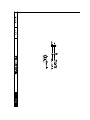
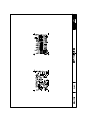
Fig 2. shows the typical IC801 drain (pin 3) waveform during
normal operation at 230V AC at 40 watts load.
Note the low amplitude leakage spike at switch off and the ¼
sine wave prior to switch on as the leakage inductance rings
with C811, so that the drain voltage falls to a minimum value
prior to switch on. (Quasi-resonant switching).
Note also the ramping current typical of a flyback converter
and the zero initial current showing that the stored energy in
T801 has reset to zero defining discontinuous operation. The
initial current spike is the discharge of C811 at switch on.

7
TUNER and IF STAGESTUNER and IF STAGES
Tuner
The main chassis is fitted with a voltage synthesis UHF/VHF
tuner (TU001) for system B/G. Control of the tuned
frequency is achieved by a voltage on pin 2 of the tuner. This
voltage is derived from integrating a 33 volt PWM switched
waveform which is produced on pin 1 of the microcontroller
IC701. Band selection is by three control lines to pins 3, 4
and 5 of the tuner.
The AFC is sampled by the microcontroller via the I²C bus
from IC504 and frequency correction is achieved by
microcontroller adjustment of the duty cycle of the PWM
which then modifies the tuner frequency.
AGC Adjustment
For most aerial input signal levels the tuner operates at
maximum gain. At high signal levels the gain of the tuner is
reduced by an AGC voltage generated in the IF stage. The
AGC output from the IF (pin 54 of IC504) is applied to pin 1
of the tuner (TU001).
The AGC maintains a maximum IF voltage of 600mV peak to
peak. The voltage level can be adjusted using the following
procedure:
Short circuit pins 1 and 2 of PL701 to enter service mode.
When in service mode use the programme up and down
keys to select service parameter 13. Using a 40MHz
Bandwidth or greater oscilloscope, monitor pin 11 of TU001.
Adjust service parameter 13 using the volume up and down
keys for 600mV on pin 11 for a single ended tuner, and
300mV for a differential output tuner. Press the TV key to
store the AGC value.
AFC Adjustment
The AFC voltage is not available at any point on the chassis;
it is read by the microcontroller via the I²C bus. Therefore,
one of the following methods can be used to correctly align
the demodulator tank coil.
a) Tune to a known channel. Using a spectrum
analyser monitor pin 11 of TU001. Fine tune the
tuner for a carrier frequency of 38.9MHz. Store the
fine tuned frequency (i.e. AFC off). Enter service
mode by applying a short circuit to pins 1 and 2 of
PL701. When in service mode use the programme
up and down keys to select service parameter 15.
Adjust service parameter 15 using the volume up
and down key until the two bits at the top right of
the screen meet the following criteria.
Left hand bit permanently set to 1.
Right hand bit toggles (either 1 to 0 or 0
to 1).
When the AFC value has been set press the TV key to store
it.
b) Inject a 600mV peak to peak signal at 38.9 MHz
into pin 1 of FL003, ground pin 2 of FL003. Enter
service mode by applying a short circuit to pins 1
and 2 of PL701. When in service mode select and
adjust parameter 15 as in a) above to meet the
following criteria.
Left hand bit permanently set to 1.
Right hand bit toggles (either 1 to 0 or 0
to 1).
When the AFC value has been set press the TV key to store
it.
Vision Decoding
The majority of the vision, deflection and colour decoding is
performed by IC504. The IF signal passes from the tuner
through the SAW filter (FL003) to filter unwanted frequencies
to IC504. It is demodulated internally and the output at pin 6
is buffered by TR502. The sound and vision components are
now separated. FL601 removes the sound from the vision
components with the unfiltered demodulated signal
containing the FM sound carrier(s) to pin 1 for demodulation
on a daughter board. Video is fed to the SCART socket
output, pin 19 of SK501 via TR503.

8
SOURCE SELECTIONSOURCE SELECTION
Source selection is controlled by the micro-controller via I²C
bus commands. The video processor (IC504) can select
between internal demodulated CVBS video on its pin 13,
external CVBS video (AV1) from pin 20 of SK501 on its pin
17 or from external CVBS video (AV2) from the yellow
Phono socket of SK6401. The internally demodulated CVBS
video is also always available on pin 20 of SK501. External
RGB is selected within IC504. Fast blanking pulses from pin
16 of SK501 are passed via an OR-ing circuit of TR301 and
TR305, TR306, TR307 and associated components to pin 26
of IC504. This pin controls the state of the RGB outputs to
the tubebase pins 19, 20, 21. It has three possible states:
9. Less than 0.9VInternal RGB from colour decoder.
10. Between 0.9 and 4.0 VExternal RGB from pins 23,
24 and 25.
11. Greater than 4.0 V Output blanked for OSD/Text
insertion.
When Teletext or OSD is displayed, pin 35 of IC701 goes
from ground to 5.0 Volts. This signal is passed via TR301
and causes pin 26 of IC504 to enter the third state above,
independent of the state of the other inputs to the OR circuit.
During mixed TV/Text mode or whilst the OSD is showing on
part of the screen this line will be switching at a high rate.
RGB mode can be selected manually by the user and in this
case the open drain output on pin 8 of the microcontroller will
be switched off and will be pulled up to 1.7 volts by R315 &
R316. TR305 then applies a voltage of about 1.0 volts to pin
26 of IC504. In the absence of a higher voltage via TR306 &
TR307 from the fast blanking input, pin 16 of SK501, this is
still sufficient to enter the external RGB mode.
Audio source switching takes place internally to the audio
processor IC6203 on this Zweiton audio version of this
chassis. It is controlled entirely by I²C commands sent from
the micro-controller. The IC selects the audio from: the Off-
Air source (which is available separately as outputs on pins
1 and 3 of SK501); from the AV1 audio inputs on pins 2 and
6 of SK501; or the AV2 audio inputs. The last of these are
the Red and White Phono sockets of SK6401. On all
external audio inputs the user may select both or just left or
right signals. This switching takes place in the audio IC. On
this chassis the Phono sockets have contacts that ensure
that if only a single audio signal is applied to the chassis via
the white Phono socket, the audio is routed to both
channels.

9
COLOUR DECODERCOLOUR DECODER
The luma signal processing and colour decoding are
implemented by IC504. The luminance and chrominance
signals are separated internally. A delay line is also
incorporated to compensate for the difference between the
luma and chroma processing times. The chrominance signal
is demodulated and the two colour difference components
are fed through IC503, a 64ns charge coupled delay line.
There are no adjustments required on the colour decoder.
On-Screen Display
The micro-controller on-screen display (OSD) supplies
blanking and RGB signals for overlaying the television
picture. Pin 35 of IC701 provides blanking pulses which are
applied to pin 26 of IC504 via TR301, to turn off the decoder
RGB output so that the OSD is clearly visible. The RGB
signals from pins 32, 33 and 34 of IC701 are applied directly
to the tube-base via TR302 to TR304 and the text drive
colour balance presets RV321 and RV322.

10
HORIZONTAL and VERTICAL DEFLECTIONHORIZONTAL and VERTICAL DEFLECTION
In addition to decoding and switching, IC504 provides
deflection processing for the horizontal and vertical time
base circuits. Using video from the IF or external source as
appropriate, the time-base section of IC504 produces
horizontal drive pulses at pin 40 to switch horizontal drive
transistors TR401 and TR402, and a differential vertical
ramp voltage at pins 46 and 47 to drive the vertical output
circuit (IC401).
All geometry adjustments are performed via the I²C bus with
the service parameters (see "Adjustments" in Servicing) with
the exceptions of horizontal width being adjusted by L404
and horizontal linearity being fixed by L405.
Horizontal Time base
The horizontal time-base is controlled in IC504 by a dual
PLL referenced to the 4.433MHz crystal oscillator. Feedback
is obtained from the flyback transformer via clamp diodes
D501 to D503 and fed onto pin 41 of IC504 as a reference
pulse.
Vertical Time base
A differential ramp is generated at pins 46 and 47 of IC504
by the charging of C534 with a simulated current source
from high value resistor R534. This drives a DC coupled
vertical deflection stage contained in IC401.
Vertical Protection
When operating normally, the vertical output stage
generates a +5.5 volt pulse during vertical flyback blanking.
This pulse is fed via TR404 and TR406 to IC504 beam
current input. Should the pulse fail the picture tube outputs
are ‘blanked off’. Zener diode ZD911, on the Aquadag, is
critical in ensuring that this circuit does not blank the picture
tube during normal operation. For diagnostic purposes,
vertical protection may be disabled by pressing the ‘2’ key on
the remote control hand unit when in service parameter ‘OA’.
This should always be re-enabled after repair (see
"Adjustments - Vertical Protection Disable" in Servicing).
Deflection and CRT supplies
43 volt and 16 volt supplies for the vertical deflection stage
are taken from secondary windings on the diode split
transformer (T402). A further secondary winding provides
power for the picture tube heaters.
A reference flyback pulse for IC504 is derived from a tap on
the primary winding providing high rise-time, and therefore,
low jitter on programme and text. The output from this tap is
also rectified and smoothed by D406/CE416 to provide a
210 volt supply for the video output amplifiers on the tube
base panel. The EHT. supply to the picture tube (23.5kV
nominal) is produced within the diode split transformer
(T402) by a 3 stage diode split overwind. The leakage
inductance of T402 and the distributed capacitance of its
overwind are tuned to harmonics of the horizontal flyback
frequency to ensure good EHT regulation. An integral thick
film resistor network is connected across the first section of
the overwind to provide adjustable focus and A1 voltages for
the picture tube.
Vertical Protection
Disable Select service parameter OA (S correction) and
press the number 2 key on the hand unit to disable the
vertical protection of IC504. This will isolate the vertical
protection circuit. After repair, vertical protection should
always be re-enabled by pressing the number 2 key again
and storing it with the TV key. (The value of parameter OA
toggles between two values when the 2 key is pressed, the
higher of which indicates vertical guard is enabled).
Auto Black level Disable
Select service parameter 02 (hue) and press the number 2
key on the hand unit to disable automatic black level
sampling in IC504. This isolates the black current signal from
the tube base. After repair, the auto black level sampling
should always be re-enabled by pressing the number 2 key
again and storing it with the TV key. (The value of parameter
02 toggles between two values when the 2 key is pressed,
the lower of which indicates black level sampling is enabled).
FBT Protection/Disable
The protection circuit works by monitoring the 16V Field HT
supply (which is rectified from active scan voltage) and
putting the TV into STANDBY mode when Field HT falls to
below 14.4V in normal operation. The under voltage
detection / Shut-down is provided by TR891, R892, R893,
and ZD893, If the Field HT drops below 14.4V, TR891 is
switched OFF allowing its collector to rise and activate the
shutdown transistor TR892 via R895,R896. This places the
TV into its STANDBY mode.

11
TUBE-BASE PANELTUBE-BASE PANEL
The picture tube amplifiers produce high voltage CRT
electrode drives from the low voltage RGB outputs of the
TDA837x (IC504) colour decoder. They also produce black
current information to maintain the greyscale characteristics
which is returned to the colour decoder.
Each video amplifier channel includes a differential amplifier
and complimentary DMOS follower. Three channels are
incorporated within IC901, a TDA6103Q triple video
amplifier. A RGB signal from the colour decoder is fed to
each video amplifier channel input.
The low frequency gain of each video amplifier channel is
approximately 46, this being determined by the ratio of the
feedback resistors to the input resistors. The gain of each
video amplifier channel above approximately 2.5MHz is
increased by including a small capacitor across one of the
two input resistors of each channel.
During the field blanking period the colour decoder
measures the total cathode circuit leakage currents at the
video amplifier outputs via TR901 to TR903. During this
period the monitoring pulses produce a voltage at R907 and
thence to pin 18 of IC504. (During normal picture operation
the monitor line is ignored by the colour decoder). These
pulses are returned to the colour decoder where they are
used to individually adjust the black current of each video
channel automatically. Thus black level picture beam current
is maintained.
The picture tube Aquadag lead is used to provide an EHT
compensation signal for picture blanking during EHT faults
and beam current information for the colour decoder for the
purpose of beam current limiting. The tube-base socket,
SK903, is fitted with internal spark gaps. Zener diode ZD911
provides tube base protection when the spark gaps flash-
over. The panel includes supplies to the tube electrodes and
the video amplifiers. Focus and A1 supplies are connected
direct from the flying leads of T402.
All video drive adjustments are done via the I²C bus (see
"Adjustments" in Servicing) with the exception of the black
level set point (150 volts) which is set by the A1 control on
the DST. An additional feature for diagnostic purposes is the
ability to disable the auto black level circuit by pressing ‘2’ on
the remote control hand set when in service parameter 02
(see "Adjustments - Auto Black level Disable" in Servicing).

12
AUDIO DEMODULATION AND POWERAUDIO DEMODULATION AND POWER
AMPLIFIERAMPLIFIER
FM Demodulation
Video and inter-carrier FM is output from pin 6 of IC504.
FL601 Traps the FM carrier from the video signal.
Composite video is then buffered by TR503 and passed to
the rest of the chassis for processing. Prior to the FM trap
(FL601), the FM carrier(s) are passed to the audio PWB for
decoding via pin 2 of PL603. FM Demodulation is then
carried out on the daughter PWB inside IC6201.
ZWEITON Decoding.
The Zweiton audio is decoded on a separate PWB. This
PWB also carries out audio switching and tone, bass,
balance, and volume control functions via I²C.
Inter-carrier FM is passed to the Dual FM Demodulator
IC6201 ( U2860B ) via pin 2 of SK6201, ceramic filters
FL6201-FL6204 selecting the two FM audio carriers (at
5.500 & 5.741 MHz respectively) required. This IC
demodulates one, or for a dual language or stereo signal –
both FM carriers. These are fed to the Zweiton (A2) decoder
IC6202 pins 7 and 8, where the pilot 54KHz signal on the
second carrier is detected and demodulated across the tank
circuit comprising L6203 and C6215 on pins 4 and 5. The
audio mode is then determined so that the appropriate audio
signals are produced on pins 13 and 14.
The audio signals are then routed to pins 3 and 5 of IC6203,
and SCART 1, pins 1 and 3 of SK501 via buffers TR6203 &
TR6204.
Volume/Tone control
Volume, tone control, & SCART audio switching are all
carried out on the audio PWB by IC6203.
The broadcast audio signals are routed to pins 2 and 5 of
IC6203; SCART 1 audio inputs from SK501 ( pins 2 & 6 ) are
routed to pins 32 and 1; and AV2 inputs from the White and
Red Phono sockets of SK6401, are routed to pins 28 & 30.
IC6203 performs all the audio switching, volume, balance,
bass, and treble functions via I²C. The processed audio
signals are then routed to the loudspeaker power amplifier
via pins 11 and 12 of SK6201.
Headphone facilities, are also controlled by IC6203; this
adjusts volume and balance only for the headphone output.
The audio signals are boosted by the low power headphone
amplifier IC6204, and sent to the headphone socket
SK6601. Additional components on the AV2 & Headphone
socket PWB de-couple the output signals and provide EMI
filtering
Audio Power Amplifier
The audio power amplifier is located on the main PWB and
is designed to output 6.0W at 10% distortion into 8 ohm
speakers. The processed audio is routed to pins 2 and 4 (left
and right respectively) of the audio power amplifier IC603
from the audio PWB via pins 11 and 12 of PL603. The power
amplifier outputs at pin 12 (left) and pin 7 (right) feed the left
and right loudspeaker plugs PL601 and PL602 respectively,
through CE614 and CE615. High frequency 'snubber'
networks R614, C617 and R615, C618 are fitted.

13
REMOTE CONTROLREMOTE CONTROL
The remote control system used is the Philip's Enhanced
RC5 protocol, with sub-address 00000.
Infra-red transmitter
The hand unit is only available as a complete replacement
unit. It is powered by two AA size cells in series, providing
3Volts.
Infra-red receiver
The chassis uses an integrated receiver, IC702, which
provides a fully demodulated output straight to the micro-
controller through R703, pulled up by R702.
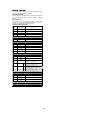
Keypad Idents and Functions
Keypad
N°
Symbol Function
1
C
Standby
2 1 N° 1
3 2 N° 2
4 3 N° 3
5 4 N° 4
6 5 N° 5
7 6 N° 6
8 7 N° 7
9 8 N° 8
10 9 N° 9
11 0 N° 0
12
b
TV
13
,=
Videotext/Mix
14 P- Programme Down
15
G
Mute
16 P+ Programme Up
17
(+
Increase Volume
18
(-
Decrease Volume
19 Red
RED-Videotext direct page
selection / Audio Menu
20 GREEN
b
GREEN-Videotext direct page
selection / Picture Menu
21 YELLOW
H
YELLOW-Videotext direct page
selection / Programme Menu
22 CYAN
B
CYAN-Videotext direct page
selection / Features Menu
23
-L
Hold/Normalize
24
.
Expand
25
/
Reveal
26
RN
Fastext index/Status
27
2
AV Select
28
P
Time/Subcode
29
Q
Audio Select
30
4
Update

14
MICROPROCESSOR CONTROL SYSTEMMICROPROCESSOR CONTROL SYSTEM
The SAA5296 controller, IC701, is an integrated
microcontroller, teletext decoder and on-screen display
(OSD) generator. It has a single 12MHz crystal XL701. At
power up, CE706 ensures a sufficiently long active high
reset pulse.
The television is controlled by I²C bus communication, digital
switching inputs and outputs, analogue-to-digital inputs and
pulse width modulation (PWM) based analogue outputs.
User Control
User input is via infra-red remote control (Philips' RC5
standard), internally decoded from the receiver IC702, or
from the four (non-matrixed) local control keys on digital
active low inputs, IC701 pins 17,18,20 and 21. The LED is
flashed each time a key is detected or remote command
received. The local keys are valid for any one key or both
end keys pressed.
Tuning
The tuning control voltage to the tuner is controlled via the
PWM at pin 1 of IC701 and integrating circuit around TR004.
Minimum voltage is at maximum mark space ratio (bottom of
each band). Band switching is controlled by active low
outputs on pins 14, 15 and 16 (low, mid, high) and
transistors TR001 to TR003.
The controller makes AFC corrections by reading on-tune
information from IC504 via the I²C bus.
As the tuner is controlled by voltage synthesis, there is no
direct correlation between the controller output and the tuned
frequency.
Non-volatile memory
The non volatile memory, IC703, holds configuration
information, user settings, parameters as applicable for the
I²C controlled ICs and the programme tuning records. It is
itself accessed by I²C.
When a new memory IC is fitted, the microcontroller will
automatically load default information, which takes a few
seconds during powerup. Regular reloading of the data, or
corruption of settings may indicate IC703 is faulty. Replacing
IC701 will not alter memory contents provided that the same
issue of software is used. If such a software upgrade takes
place it would be wise to note the parameters listed in
section 12 to facilitate their re-entry.
The default data does not have any preset tuning
information, although programmes 1 to 10 are stored.
Standby control
The power supply is enabled when pin 46 of IC701 goes low.
When high, only the 5V micro-controller supply on pin 44
remains on. Teletext and analogue supplies on 38/39 are
switched off. The LED is illuminated to full brightness.
Note: The scan does not become active when the power is
enabled, but when the controller has written all control
parameters to IC504.
AV switching
Inputs from pins 8 and 16 of SCART 1 are sampled by
analogue to digital conversion on pins 9 and 11 of IC701
respectively. The input levels are adjusted such that the
controller will automatically switch to AV1 when pin 8 is
above 4.5V and RGB when pin 16 is above 1V, in
accordance with EN standards. The time constant on pin 16
ensures the controller will not detect real time RGB insertion
using pin 16.
OSD/teletext
The OSD generator and teletext sections of the IC are
powered separately from the microcontroller by 5V on pins
38 & 39. Line and field timings are obtained from V-sync.
input on pin 37 and H-sync. on pin 36. Teletext is obtained
from the CVBS input on pin 23. The RGB outputs on pins 34,
33 and 32 respectively are inserted into the TV output when
gated by the VDS signal on pin 35. Text contrast is
controlled by the peak reference level on pin 31, generated
from the microcontroller PWM output on pin 30 via TR308.

15
SERVICING
ADJUSTMENTSADJUSTMENTS
In order to make service adjustments the TV should have a
suitable signal tuned in; ideally, a geometry test card. To set
OSD contrast, a teletext signal is recommended.
The controller has a service mode of operation where
adjustments are made and configuration options set. To
enter service mode, place a shorting link across the
terminals of PL701 or ground IC701 pin 12. Note, to use the
normalise key or change programmes, as required for some
adjustments, it is necessary to exit service mode by
removing the link.
In service mode, the display shows two 2-digit hexadecimal
numbers on the left of the screen; the left hand one is the
service parameter number, the right hand one is the value
for that parameter. Some parameters are identified by a two-
letter code instead of a number, see below.
For example :- 0A 1F shows parameter ten ( 0A hex) at
value thirty one (1F hex)
Use the programme up and down keys to change the
parameter number, and the volume up and down keys to
adjust the value of the current parameter ( local or hand unit
controls ).
The volume control adjusts the settings only within the valid
range ( lower six bits ). Keys 1 and 2 on the hand unit are
used for other adjustments. Do not press 1 or 2 except
where indicated in the notes below.
TO STORE THE CHANGES, PRESS THE ‘TV’ KEY ON
THE HAND UNIT BEFORE REMOVING THE SERVICE
MODE LINK. If this is not done, certain changes may be lost
when the TV changes channel or is switched off. The word
"STORED" appears at the top left of the screen when the
adjustments are saved.
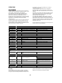
Service parameters 01 to 16 apply to the control registers of
IC504 as shown in the following table.
N° Default Value Function Action
00 02 System control Do not adjust
01 D0 System control Do not adjust
02 1F Hue (SCART NTSC 4.43 playback only) Use picture menu control instead
03 13 Horizontal shift Adjust to centre picture horizontally
04-07 00 E-W control Not used on this chassis
08 25 Vertical slope ( linearity ) Adjust for vertical linearity
09 09 Vertical amplitude ( height ) Adjust for correct picture height
0A 5F S correction Adjust for best vertical S-correction
0B 1B Vertical shift Adjust to centre picture vertically
0C 1F White point - Red
0D 1F White point - Green See notes below
0E 1F White point - Blue
0F 08 Peaking (sharpness) Use picture menu control instead
10 1F Brightness Use picture menu control instead
11 9F Saturation Use picture menu control instead
12 20 Contrast Use picture menu control instead
13 34 AGC take over point See notes below
14 40 FM sound volume Set to 40 hex
15 3F IF PLL ( AFC ) adjustment See notes below
16 00 Vertical zoom Not used on this chassis
Parameters above 16 are designated by two letter codes (except text contrast). These control configuration and have limited
ranges.
Text mode FF
Text contrast – changes to teletext mix
mode
Set as preferred, see note below.
Ph 01 Headphone option (affects audio menu) 00 if no headphone socket, 01 if fitted
Ex 00 Export ( VHF/UHF ) setting 00 for UHF only, 01 if multiband tuner
00 Single SCART
01 Single SCART plus Phono inputs
AV 01 AV socket configuration
02 Dual SCART
St 10
Stereo chipset indicator, not adjustable, if
00 Audio IC failed.
10 Zweiton (A2) Audio System detected
G1 00 Level Adjust
Set to give correct audio levels on Scart
Outputs
G2 00 Stereo Adjust Set to give maximum Stereo separation
N- 07 NICAM Error Rate Un-mute Not used on this chassis
N+ 30 NICAM Error Rate Mute Not used on this chassis
If possible, it is advisable to make a note of the existing values prior to commencing servicing.
HT setting :
Reduce brightness and contrast to minimum, using the on
screen picture menu (service link not fitted), and press the
TV key to clear the OSD Adjust RV820 for 115±0.5V at the
junction of D814/CE817. Press the normalise key to restore
brightness and contrast to the mid-point settings.

16
A1 control
This should be set for 150V black level at the tubebase
cathodes with the settings normalised, using the lower
control on the rear of the flyback transformer.
White points
These should be adjusted viewing a picture with little light
area, to prevent beam current limiting. The parameters
should be adjusted for a black to white swing of 65±1V on
each of the three cathodes, with picture normalised.
Text contrast :
White balancing of the red and blue outputs relative to the
green should be carried out to ensure pure white text, using
RV321 (R) and RV322 (B). As the picture outputs are
automatically balanced, text white may be set using picture
white as a reference, once the drives have been set. The
text contrast itself should be adjusted such that the
Text/OSD white parts are approximately 75% of the intensity
of a peak white area of a test pattern; this corresponds to the
75% grey blocks in part of a ‘Philips 5544’ type test pattern.
When the text contrast service parameter is selected the TV
switches to teletext mix mode, page 101; if no text is present
P100 will still appear in the top left corner of the screen
together with some text on the bottom row of the display.
There is no on-screen parameter, adjust with volume control
as normal and change parameter with programme up/down
keys.
IF PLL (AFC)
This should be adjusted with the aerial input grounded and a
38.9MHz signal input direct to the SAW filter (care must be
taken to check whether the tuner output is symmetrical, or
one side grounded). If this is not possible, an approximate
setting may be made using the aerial signal.
The display at the top right of the screen shows two digits,
each 1 or 0. The left hand digit is 1 when the IF frequency is
within an 80kHz window of the centre point. The right hand
digit is 1 when above the exact reference frequency, 0 when
below. Thus parameter 15 should be adjusted to the single
step where the left digit is 1 and the right digit just changes
from 0 to 1.
Important: the range of parameter 15 is 00 to 7F.
When the aerial signal is tuned, the AFC can be seen
stepping over the tuning point once per second ( the right
hand digit changes between 0 and 1 ). If the stepping
remains erratic, recheck the setting. If the change does not
occur, ensure AFC is enabled by using the manual search
tune option in the tuning menu.
AGC
AGC take over point should be adjusted such that the tuner
output to the SAW filter is 600mV
pk-pk
( 300mV per side for
symmetrical tuner output ) without sound.
Focus :
Adjust the upper control on the rear of the flyback
transformer for best focus.
Positioning :
Centre the picture horizontally and vertically and set the
height for 6% overscan ( the edge castellations of the test
card will just show at the edge of the screen). It may be
necessary to readjust after the linearity has been set. The
width is not set by the microcontroller; set for 6% overscan
using the core of L404.
Linearity :
With a test pattern showing equal vertical intervals, adjust
vertical slope for evenly spaced intervals at the top and
bottom of the picture, then adjust vertical S-correction to
even the spacing across the whole height of the picture.
Vertical Protection Disable
Select service parameter OA (S correction) and press the
number 2 key on the hand unit to disable the vertical
protection of IC504. This will isolate the vertical protection
circuit. After repair, vertical protection should always be re-
enabled by pressing the number 2 key again and storing it
with the TV key. (The value of parameter OA toggles
between two values when the 2 key is pressed, the higher of
which indicates vertical guard is enabled).
Auto Black level Disable
Select service parameter 02 (hue) and press the number 2
key on the hand unit to disable automatic black level
sampling in IC504. This isolates the black current signal from
the tube base. After repair, the auto black level sampling
should always be re-enabled by pressing the number 2 key
again and storing it with the TV key. (The value of parameter
02 toggles between two values when the 2 key is pressed,
the lower of which indicates black level sampling is enabled).

17
DEUTSCHDEUTSCH
SICHERHEITSICHERHEIT
SICHERHEITSVORKEHRUNGENSICHERHEITSVORKEHRUNGEN
WARNUNG: Die folgenden Vorkehrungen müssen
eingehalten werden.
ALLE PRODUKTE
12. Bevor die Grundplatte gewartet wird, sollte ein
Trenntrafo zwischen die Netzleitung und das
Produkt eingebracht werden.
13. Wenn die Grundplatte in das Gehäuse
zurückgestellt wird, stellen Sie sicher, dass alle
Schutzvorrichtungen wieder an ihrem Ort sind.
14. Wenn Wartung erforderlich ist, halten Sie die
originale Verdrahtungsart ein. Besondere Vorsicht
ist nötig, um die korrekte Verdrahtungsart in jedem
Hochspannungsstromkreis zu gewährleisten.
15. Viele elektrische und mechanische Teile von
HITACHI Produkten haben besondere
sicherheitsbezogene Eigenschaften. Diese
Eigenschaften fallen oft nicht ins Auge, aber der
durch sie gewährte Schutz kann nicht unbedingt
erreicht werden, wenn man Ersatzteile benutzt, die
für höhere Spannung, Leistung usw. ausgelegt
sind. Ersatzteile, die diese besonderen
Sicherheitsmerkmale haben, sind in den
Prinzipskizzen und Ersatzteillisten an einem !
zu erkennen.
Der Gebrauch von Ersatzteilen, die nicht
dieselben Sicherheitsmerkmale haben wie die
empfohlenen HITACHI Ersatzteile, wie sie in der
Ersatzteilliste aufgeführt sind, kann zu
elektrischem Schlag, Feuer, Röntgenstrahlung
und anderen Gefahren führen.
16. Immer die originalen Abstandsstücke ersetzen und
die Leitungslängen beibehalten. Wo ein
Kurzschluss passiert ist, die Teile ersetzen, bei
denen Überhitzung nachzuweisen ist.
17. Der Isolierwert sollte bei 500 V Gleichstrom
zwischen den Hauptpolen und allen zugänglichen
Metallteilen nicht unter 2M Ohm liegen.
18. Bei der Prüfung auf Durchschlagsfestigkeit sollte
kein Überschlag oder Durchschlag vorkommen,
wenn zwei Sekunden lang 3 kV Wechselstrom
oder 4,25 kV Gleichstrom zwischen den
Hauptpolen und allen zugänglichen Metallteilen
angelegt wird.
19. Bevor das gewartete Produkt dem Kunden
zurückgegeben wird, muss der Wartungstechniker
das Gerät gründlich prüfen, um sicherzustellen,
dass es betriebssicher ist ohne das Risiko eines
elektrischen Schlages. Der Wartungstechniker
muss sicherstellen, dass keine vom Hersteller im
Gerät eingebaute Schutzvorkehrung schadhaft
geworden ist oder bei der Wartung unabsichtlich
beschädigt wurde.
CE KENNZEICHEN
2. HITACHI Produkte enthalten eventuell das CE
Kennzeichen auf dem Leistungsschild, welches
angibt, dass das Produkt Teile enthält, die eigens
zugelassen sind, um bis zu einem spezifizierten
Niveau elektromagnetische Störfreiheit zu
bewirken.
3. Wenn Sie irgendein Teil in diesem Produkt
ersetzen, benutzen Sie bitte nur das korrekte Teil,
das in der Ersatzteilliste aufgeführt ist, um
sicherzustellen, dass dieser Standard eingehalten
wird, und geben Sie acht, die Verdrahtungsart in
ihren ursprünglichen Zustand zurück zu versetzen,
weil das einen Einfluss auf die elektromagnetische
Abstrahlung/Störsicherheit haben kann.
BILDRÖHRE
5. Die Leitungsausgangsstufe kann Spannungen von
mehr als 25 kV entwickeln; wenn die
Höchstspannungskappe entfernt werden muss,
entladen Sie die Anode zum Gehäuse über einen
hochohmigen Widerstand, bevor Sie sie aus der
Bildröhre entfernen.
6. Hochspannung sollte immer auf den festgelegten
Wert des Gehäuses beschränkt bleiben und nicht
mehr. Betrieb bei höherer Spannung kann zum
Versagen der Bildröhre oder zu hoher
Spannungszufuhr führen und kann unter
Umständen auch Röntgenstrahlung hervorbringen,
die leicht über dem Konstruktionsniveau liegt. Die
Hochspannung darf auf keinen Fall 29 kV am
Gehäuse überschreiten (außer bei
Projektionsfernsehern).
7. Die Hauptquelle der Röntgenstrahlung im Produkt
ist die Bildröhre. Die Bildröhre, die für die oben
erwähnte Funktion in diesem Gehäuse benutzt
wird, ist eine Spezialkonstruktion zur Begrenzung
der Röntgenstrahlung. Um den Schutz vor der
Röntgenstrahlung zu behalten, ersetzen Sie bitte
die Röhre durch denselben Typ wie den
ursprünglichen von HITACHI zugelassenen.
8. Halten Sie die Bildröhre bei der Handhabung vom
Körper weg. Sie dürfen die Bildröhre nur dann
installieren, entfernen oder handhaben, wenn Sie
eine nicht splitternde Schutzbrille tragen.
Personen ohne derartigen Schutz sollten
ferngehalten werden, solange Bildröhren
gehandhabt werden.
LASER
Wenn das Produkt einen Laser enthält, setzen Sie sich
keinesfalls direkt dem Strahl aus, wenn die Abdeckung
geöffnet ist oder wenn die Verriegelung versagt.

18
SICHERHEIT UND ISOLIERUNGSICHERHEIT UND ISOLIERUNG
>Unter keinen Umständen dürfen irgendwelche Reparatur-
oder Wartungsarbeiten durch irgendwelche Personen
durchgeführt werden, die nicht erfahrene und geschulte
Techniker sind. Die meisten in der Chassis enthaltenen
Schaltungen sind von dem Wechselstromanschluß durch
T801, C831, R821, IC802 und 6mm Luftspalte getrennt. Um
diesen Sicherheitsgrad zu erhalten muß man es sichern,
daß, nach jeder Art von Reparatur, irgendwelche Luftspalte
oder Leckstromwege nicht durch irgendwelche
hervorstehende Drähte usw beeinträchtigt sind, nach dem
Ersatz irgendwelcher Bauteile.
ANMERKUNG: Obwohl die Ausgangsleitungen des
Stromteils von dem AC Netz abgetrennt sind, sind der
Gleichrichter und die Stromreglerschaltungen nicht
abgetrennt. Aus diesem Grunde muß das externe AC
Stromnetz bei irgendwelchen Reparaturarbeiten an der
Stromversorgung durch einen Transformator mit
Nennlaststärke von mindestens 200W isoliert werden.
Die Stromversorgung bleibt 30 - 60 Sekunden lang geladen,
nachdem das Netz abgeschaltet ist. Man muß daher
achtgeben, keine Teile der Stromversorgung während
dieses Zeitintervalls zu berühren.
Bauteile, die im Teilverzeichnis mit ! angezeigt sind,
entsprechen Sicherheitsnormen, und dürfen nur durch
Bauteile ersetzt werden, die von unserer
Kundendienstabteilung geliefert sind, oder Genehmigung
tragen. Es wird außerdem empfohlen, daß irgendwelche
Bauteile, die nicht das Sicherheitssymbol tragen, durch den
selben Typ wie die Originalteile ersetzt werden. Diese
Warnung betrifft insbesonders Widerstände, die auf den
Prints auf ihren Drähten stehen.
Betrieb und Adjustierung der Elektronikchassis
Die meisten Funktionen auf der Chassis werden innerhalb
der integrierten Schaltung IC504, und damit verbundenen
Bauteilen implementiert. Diese werden durch den
Microcontroller IC701 via den I
2
FC Bus, einen Zweidrahtbus
(SDA, d.h. Serial Data, und SCL, d.h. Serial Clock)
gesteuert. Der Microcontroller hat 20 einstellbare Parameter
zwischen 00 und 13 (H), welche zur Steuerung der
Schaltung IC504 dienen. (Siehe Justierungen für näheres
zum Einregeln und Abgleichen).
Hantierungsevorkehrungen - Elektrostatische Ladungen
Der Empfänger enthält Bauteile, die durch elektrostatische
Ladungen bei Hantieren beschädigt werden können. Um
Schäden zu vermeiden, muß man alle Löteisen erden und
es ist ratsam, im idealen Falle, daß Wartungspersonal
Erdungsarmbänder trägt, die durch einen 1 Megohm
Widerstand geerdet sind. Falls solches nicht praktisch ist, so
muß der Wartungstechniker sich entladen, indem er eine
geerdete Stelle berührt. Elektrostatisch empfindlichen Teilen
müssen in geeigneten leitenden Behältern verpackt werden.
WICHTIG: Obwohl die Empfängerchassis isoliert ist, muß
man das AC Netz während der Wartung oder des Ersatzes
solcher elektrostatische empfindlicher teile abschalten.

19
BEDIENUNGSANLEITUNGBEDIENUNGSANLEITUNG
BETRIEBSVORSCHRIFTENBETRIEBSVORSCHRIFTEN
Einschaltung
Der Fernsehapparat schaltet sich in seinen letzten
Betriebsstatus ein, d.h. entweder auf "EIN" oder auf
"WARTEZUSTAND". Falls der Fernsehapparat im
Wartezustand ist, so drücke man irgendwelche
Nummerntaste oder die TV Taste b auf der
Handsteuerung, um einzuschalten.
Abstimmen
Automatisches Abstimmen wird von dem SETUP-Menü aus
durchgeführt. (Siehe "Automatische Abstimmung" weiter
unten). Manuelles Abstimmen und genaues Abstimmen
werden von dem 'MANUAL' Menü aus durchgeführt. (Siehe
"Manuelle Abstimmung" weiter unte).
Menüs
Menüs werden mittels der farbigen Tasten gewählt: ROT =
Audio, GRÜN = Video, GELB = Programme (mit Abstimmen
verbunden) und BLAU = andere Merkmale (Features).
Um etwas von einem Menü zu wählen, verwendet man die '
Taste., um den Kursor (hervorgehobenen Block) hinauf zu
schieben, ' oder $ um den Kursor hinunter zu schieben.
Zum Wählen verwendet man die % oder & Taste, um die
Einstellung entsprechend zu ändern. Auch dienen diese
Tasten dazu, den Kursor nach links oder nach rechts zu
verschieben.
Allgemein betätigt man die TV-Taste b um aus einem
Menü auszutreten, und wieder zum TV zurückzugehen.
Programm-Menü
Die GELBE Taste betätigen. Diese liefert eine Übersicht, in
Tabellenform, aller sechzig Programmstellen. Jede der
sechzig Programmstellen wird angezeigt, und danach der
Programmnamen, vier rote Striche oder vier weiße Striche.
Rote Strichen bedeuten, daß kein Programm abgestimmt
und gespeichert wurde, und weiße Strichen bedeuten, daß
ein Programm abgestimmt und an dieser Stelle währen der
automatischen Abstimmung gespeichert wurde.
Verwenden Sie die Tasten %, &, ' oder $ um Programme zu
wählen.
Anmerkung: Es könne gleichzeitig nur dreißig
Programme auf dem Bildschirm angezeigt werden,
entweder Programme 0-29 oder 30-59. Verwenden Sie
die %% oder && Tasten um die Anzeige nach Bedarf zu
ändern.
Einstellungsmenü
Aus dem Programm-Menü die GELBE Taste betätigen, um
das Einstellungs (SETUP)-Menü zu wählen.
Automatisches Abstimmen
Zum automatischen Abstimmen aller TV Stationen betätigt
man die BLAUE Taste von dem SETUP (Einstellungs-)
Menü.Dadurch erhält der Fernsehapparat den Befehl, alle
Stationen z\u finden, und ihnen individuelle
Programmnummern zu verleihen.
Anmerkung: Während automatische Abstimmung stattfindet,
kann man diese abstellen, indem man die BLAUE Taste
betätigt; dadurch werden alle Sender, die abgestimmt
wurden, seitdem das automatisches Abstimmen begann,
gelöscht.
Manuelles Abstimmen
Zum manuellen Abstimmen eines TV Senders betätigt man
die GRÜNE Taste von dem SETUP Menü aus. Auf diese
Weise kann man TV Sender abstimmen, und an jeder
erwünschten Programmstelle zwischen 0 und 59 speichern.
ABSTIMMEN: Zum manuellen Abstimmen geht man das
Band hinauf oder hinunter, je nachdem ob man die %
(hinunter) oder die & (hinauf) Taste betätigt. Dabei wird die
Automatic Frequency Control (AFC) automatisch überwältigt.
SUCHEN: Hier wird eine Suche nach dem nächsten TV
Sender am Band hinauf oder hinunter durchgeführt, je
nachdem ob man die % (hinunter) oder die & (hinauf) Taste
betätigt. Falls man die AFC (Automatic Frequency Control
durch manuelles Abstimmen überwältigt hat, so wird AFC
wieder beim Abstimmen des gegenwärtigen Senders
eingestellt.
BAND: Mittels dieser Option kann man das Frequenzband
ändern, obwohl das Umschalten erst dann stattfindet,
nachdem Suchen oder manuelle Abstimmung durchgeführt
wird.
SPEICHERN: Wird dazu verwendet, um die gegenwärtige
Abstimmungsinformation zu retten, einschließlich AFC
Überwältigungsinformation, Band usw betreffend den
gewählten Sender.
Audio-Menü
Zum Erreichen der Audio-Einstellungen betätigt man die
GRÜNE Taste aus dem SETUP-Menü.
Aus diesem Menü kann man Lautstärke, Balance,
Hochfrequenz (Treble), Tieffrenenz (Bass), Tonart und
Raumeigenschaften (Spatial) ändern. Falls die Kopfhörer-
Option zugegen und konfiguriert ist, so ist es auch möglich,
die Lautstärke und Balance an dem Kopfhörer einzustellen.
MODUS - Dieser gestattet es, den Ton-Modus zu
ändern, entsprechend der Art der Sendung oder
anderer äußeren Quelle die zur Verfügung stehen,
auf FM Mono. FM Stereo, FM Doppelsprache I,
FM Doppelsprache II, AV Stereo, ASV
Doppelsprache I und ASV Doppelsprache II.
Anmerkung: Es stehen nicht alle Modi
gleichzeitig zur Verfügung
Bildmemnü
Die GRÜNE Taste betätigen. Es können Helligkeit, Kontrast,
Farbe, Schärfe und Farbton eingestellt werden.
SPEICHERN Wird zum Speichern der neuen
Bildeinstellungen verwendet.
Merkmal-Menü
Die BLAUE Taste betätigen. Von diesem Menü aus kann
man die Programmquellen-Auswahl ändern. Die lokalen
Kindersperrungs (Child-Lock) Einstellungsknöpfe können in
Kraft/außer Kraft gesetzt werden, und der
Schlafzeiteinsteller (Sleep Timer) kann eingestellt/geändert
werden.
Ton-Modus
Man betätigt die 3 Taste, wenn nicht im Menü-Modus, um
den Tonmodus auf Mono, Stereo, Doppelsprache I oder
Doppelsprache II, entsprechend der Sendung, zu ändern.
Bilderquelle Ändern
Um AV1, AV2, RGB oder TV Quelle zum Ansehen zu
wählen (die eigentlichen Quellen hängen von dem
spezifischen Modell ab), drücke man wiederholt auf die
2 Taste (wenn nicht im Menü-Modus, bis die erwünschte
Quelle gewählt ist, welche an der links oberen Ecke des
Bildschirmes angezeigt ist (siehe Abschnitt 2.14 im
Folgenden). Als Alternative kann man die Quelle von dem
Merkmals (Features)- Menü ändern.
Text/gemischte Modi
Betätigung der , Taste von dem Bildmodus aus stellt den
TEXT-Modus ein. Weitere Betätigung dieser Taste schaltet
den Apparat zwischen seinen TEXT und GEMISCHTEN
(MIX) Modi um.
Um wieder zum TV-Bild zu gelangen, betätigt man die b
Taste.
Normalisieren
Man betätigt die L Taste (wenn nicht im Menü-Modus),
um die Helligkeit, Kontrast, Farbe und Schärfe Einstellungen
etwa in die Mitte ihrer Bereiche zu setzen.
Status-Anzeige
Es erscheint auf dem Bildschirm eine Anzeige der
gegenwärtigen Programmnummer und Programmnamen,
sowie Status der verschiedenen Betriebsmodi, nachdem
Seite wird geladen ...
Seite wird geladen ...
Seite wird geladen ...
Seite wird geladen ...
Seite wird geladen ...
Seite wird geladen ...
Seite wird geladen ...
Seite wird geladen ...
Seite wird geladen ...
Seite wird geladen ...
Seite wird geladen ...
Seite wird geladen ...
Seite wird geladen ...
Seite wird geladen ...
Seite wird geladen ...
Seite wird geladen ...
Seite wird geladen ...
Seite wird geladen ...
Seite wird geladen ...
Seite wird geladen ...
Seite wird geladen ...
Seite wird geladen ...
Seite wird geladen ...
Seite wird geladen ...
Seite wird geladen ...
Seite wird geladen ...
Seite wird geladen ...
Seite wird geladen ...
Seite wird geladen ...
Seite wird geladen ...
Seite wird geladen ...
Seite wird geladen ...
Seite wird geladen ...
Seite wird geladen ...
Seite wird geladen ...
Seite wird geladen ...
Seite wird geladen ...
Seite wird geladen ...
-
 1
1
-
 2
2
-
 3
3
-
 4
4
-
 5
5
-
 6
6
-
 7
7
-
 8
8
-
 9
9
-
 10
10
-
 11
11
-
 12
12
-
 13
13
-
 14
14
-
 15
15
-
 16
16
-
 17
17
-
 18
18
-
 19
19
-
 20
20
-
 21
21
-
 22
22
-
 23
23
-
 24
24
-
 25
25
-
 26
26
-
 27
27
-
 28
28
-
 29
29
-
 30
30
-
 31
31
-
 32
32
-
 33
33
-
 34
34
-
 35
35
-
 36
36
-
 37
37
-
 38
38
-
 39
39
-
 40
40
-
 41
41
-
 42
42
-
 43
43
-
 44
44
-
 45
45
-
 46
46
-
 47
47
-
 48
48
-
 49
49
-
 50
50
-
 51
51
-
 52
52
-
 53
53
-
 54
54
-
 55
55
-
 56
56
-
 57
57
-
 58
58


Hitachi CP2155TA Benutzerhandbuch
- Kategorie
- LCD-Fernseher
- Typ
- Benutzerhandbuch
in anderen Sprachen
- English: Hitachi CP2155TA User manual
Verwandte Artikel
Andere Dokumente
-
Sharp SD-EX200 Benutzerhandbuch
-
Crest Audio LQ 10P Benutzerhandbuch
-
Peavey 10P Benutzerhandbuch
-
Grundig GV 900 SV/1 Servise Manual
-
Motorola CLEARTONE CM5000 Basic Service Manual
-
-
 Micon T20 Benutzerhandbuch
-
Grundig CUC 7301 Bedienungsanleitung
-
 JB DV-22N Digital Vacuum Gauge Benutzerhandbuch
-

