Toro Assist Bar Kit, TimeCutter/Titan Riding Mower Installationsanleitung
- Typ
- Installationsanleitung

Form No. 3465-913 Rev A
Assist Bar Kit
161-4450
Stützgriff-Kit
161-4450
Kit barre de maintien
161-4450
Set met hulpstang
161-4450
www .T oro.com.
*3465-913*


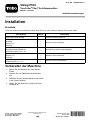
Form No. 3465-892 Rev A
Assist Bar Kit
T imeCutter
®
/T itan
®
Riding Mower
Model No. 161-4450
Installation Instructions
Installation
Loose Parts
Use the chart below to verify that all parts have been shipped.
Description
Qty .
Use
No parts required
–
Prepare the machine.
Assist handle 1
Pin (grooved)
1
W asher (3/8 inch)
1
Retaining ring 1
Assemble the assist handle.
Assist-handle bracket 1
Hex ange-head bolt (thread-forming—5/16
x 3/4 inch)
2
Install the assist-handle bracket.
Pin (grooved)
1
W asher (3/8 inch)
1
Retaining ring 1
Install the assist handle.
Handle retainer 1
Shoulder screw (1/4 x 1/2 inch)
1
Install the handle retainer .
Preparing the Machine
1. Park the machine on a level surface.
2. Disengage the blade-control switch.
3. Move the motion control levers outward to the
PARK position.
4. Shut of f the engine and remove the key .
© 2023—The T oro® Company
81 1 1 L yndale A venue South
Bloomington, MN 55420
Register at www .T oro.com.
Original Instructions (EN)
Printed in the USA
All Rights Reserved
*3465-892*

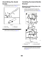
Assembling the Assist
Handle
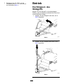
1. Assemble the grooved pin through the hole in
the assist handle as shown in Figure 1 .
g464941
Figure 1
1. Assist handle 3. Retaining ring
2. W asher (3/8 inch) 4. Pin (grooved)
2. Secure the pin to the handle with the washer
(3/8 inch) and the retaining ring ( Figure 1 ).
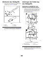
Installing the Assist-Handle
Bracket
Measuring and Drilling Holes into
the Frame Rail
1. Hold the assist-handle bracket against the
left frame rail and position it according to the
measurement for your particular model ( Figure
2).
g464996
Figure 2
A: T imeCutter models. B: T itan models.
1. Assist-handle bracket
3. 1 13 mm (4-7/16 inches)
2. Left frame rail 4. 146 mm (5-3/4 inches)
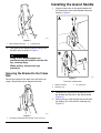
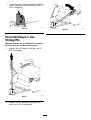
2. Using the assist-handle bracket as a template,
draw marks through the holes onto the frame
rail ( Figure 3 ).
2

g465023
Figure 3
1. Mark and drill holes here.
2. Left frame rail
3. Drill holes at the marked locations using a drill
bit (9/32 inch) as shown in Figure 3 .
W ARNING
Using a drill without proper eye
protection may allow debris to enter the
eye, causing injury .
When drilling, always wear eye
protection.
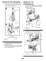
Securing the Bracket to the Frame
Rail
Secure the bracket to the side of the left frame rail
using 2 thread-forming hex ange-head bolts.
g465027
Figure 4
1. Hex ange-head bolt (thread-forming—5/16 x 3/4 inch)
Installing the Assist Handle
1. Align the lower hole in the assist handle with
the closed slot in the assist-handle bracket as
shown in Figure 5 .
g465144
Figure 5
T imeCutter model shown
1. W asher (3/8 inch) 3. Pin (grooved)
2. Retaining ring
2. Assemble the grooved pin through the slot in
the bracket and the hole in the assist handle
(Figure 5 ).
3. Secure the pin to the bracket and handle with
the washer (3/8 inch) and the retaining ring
(Figure 5 ).
3

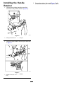
Installing the Handle
Retainer
1. Remove the existing shoulder screw that
secures the left pod the machine ( Figure 6 ).
g465175
Figure 6
1. Existing shoulder screw
2. Left pod
2. Align the handle retainer to the left pod as shown
in Figure 7 .
g465176
Figure 7
1. Shoulder screw (1/4 x 1/2
inch)
2. Retainer
3. Secure the retainer to the pod ( Figure 7 ) with
the shoulder screw (1/4 x 1/2 inch) from the kit.
4

Operation
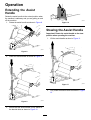
Extending the Assist
Handle
Rotate the assist handle to the extend position when
the machine is stationary and you are getting on and
of f the machine.
1. Rotate the assist handle as shown in Figure 8 .
g465177
Figure 8
2. Lower the assist handle as shown in Figure 9 .
g465178
Figure 9
3. Ensure that the assist handle is fully seated in
the bracket slots as shown in Figure 10 .
g465179
Figure 10
Stowing the Assist Handle
Important: Rotate the assist handle to the stow
position when operating the machine.
1. Lift the assist handle as show in Figure 1 1 .
g465190
Figure 1 1
2. Fully rotate the assist handle as shown in Figure
12 .
5

g465191
Figure 12
6

Form No. 3465 - 894 Rev A
Stützgriff - Kit
T imeCutter
®
/T itan
®
Aufsitzrasenmäher
Modellnr . 161 - 4450
Installationsanweisungen
Installation
Einzelteile
Prüfen Sie anhand der nachstehenden T abelle, dass Sie alle im Lieferumfang enthaltenen T eile erhalten haben.
Beschreibung Menge V erwendung
Keine T eile werden benötigt
–
Bereiten Sie die Maschine vor .
Stützgrif f
1
Nutenstift
1
Scheibe (⅜")
1
Haltering 1
Montieren Sie den Stützgrif f.
Stützgrif f - Halterung
1
Sechskant - Bundkopfschraube
(selbstschneidend, 5/16" x ¾")
2
Anbringen der Halterung des Stützgrif fs.
Nutenstift
1
Scheibe (⅜")
1
Haltering 1
Montieren Sie den Stützgrif f.
Grif fhalterung
1
Ansatzschraube (¼" x ½")
1
Montieren Sie die Grif fhalterung.
V orbereiten der Maschine
1. Parken Sie die Maschine auf einer ebenen
Fläche.
2. Kuppeln Sie den Zapfwellenantriebsschalter
aus.
3. Schieben Sie die Fahrantriebshebel nach außen
in die P ARKEN - Stellung.
4. Stellen Sie den Motor ab und ziehen Sie den
Schlüssel ab.
© 2023—The T oro® Company
81 1 1 L yndale A venue South
Bloomington, MN 55420
Registrieren Sie Ihr Produkt unter
www .T oro.com.
Originaldokuments (DE)
Druck: USA
Alle Rechte vorbehalten
*3465 - 894*

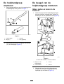
Montieren des Stützgriffs
1. Setzen Sie den Nutenstift durch die Bohrung im
Stützgrif f ein, wie in Bild 1 dargestellt.
g464941
Bild 1
1. Stützgrif f
3. Haltering
2. Scheibe (⅜")
4. Nutenstift
2. Befestigen Sie den Stift mit der Unterlegscheibe
(⅜“) und dem Sicherungsring am Stützgrif f ( Bild
1).
Anbringen der Halterung
des Stützgriffs
Ausmessen und Bohren von
Löchern in die Rahmenschiene
1. Halten Sie die Halterung des Stützgrif fs an die
linke Rahmenschiene und positionieren Sie
sie entsprechend den Abmessungen für Ihr
jeweiliges Modell ( Bild 2 ).
g464996
Bild 2
A: T imeCutter - Modelle. B: T itan - Modelle.
1. Stützgrif f - Halterung
3. 1 13 mm
2. Linke Rahmenschiene
4. 146 mm (5 3/4“)
2. Benutzen Sie die Halterung des Stützgrif fs als
Schablone und zeichnen Sie die Löcher auf der
Rahmenschiene an ( Bild 3 ).
2

g465023
Bild 3
1. Markieren und bohren Sie
die Löcher hier .
2. Linke Rahmenschiene
3. Bohren Sie an den markierten Stellen Löcher
mit einem Bohrer (9/32 Zoll), wie in Bild 3
dargestellt.
W ARNUNG:
Bei V erwendung einer Bohrmaschine
ohne entsprechenden Augenschutz
können Rückstände in das Auge
gelangen und es beschädigen.
T ragen Sie beim Bohren immer eine
Schutzbrille.
Befestigen der Halterung an der
Rahmenschiene
Befestigen Sie die Halterung mit zwei
selbstschneidenden Sechskant - Bundkopfschrauben
an der Seite der linken Rahmenschiene.
g465027
Bild 4
1. Sechskant - Bundkopfschraube (selbstschneidend,
5/16" x ¾")
3

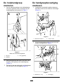
Montieren des Stützgriffs
1. Fluchten Sie die untere Bohrung des Stützgrif fs
mit dem Langloch in der Stützgrif f - Halterung
aus, wie in Bild 5 dargestellt.
g465144
Bild 5
T imeCutter - Modell dargestellt
1. Scheibe (⅜") 3. Nutenstift
2. Haltering
2. Setzen Sie den Nutenstift durch das Langloch
in der Stützgrif f - Halterung und der Bohrung im
Stützgrif f ein ( Bild 5 ).
3. Befestigen Sie den Stift mit der Unterlegscheibe
(⅜“) und dem Sicherungsring an der Halterung
und am Stützgrif f ( Bild 5 ).
Montieren der
Griffhalterung
1. Entfernen Sie die vorhandene Ansatzschraube
mit der die linke V erkleidung an der Maschine
befestigt ist ( Bild 6 ).
g465175
Bild 6
1. V orhandene
Ansatzschraube
2. Linke V erkleidung
2. Fluchten Sie die Grif fhalterung an der linken
V erkleidung aus, wie in Bild 7 dargestellt.
g465176
Bild 7
1. Ansatzschraube (¼" x ½")
2. Halter
4

3. Befestigen Sie den Halter mit der
Ansatzschraube (¼" x ½“) des Kits an
der V erkleidung ( Bild 7 ).
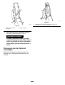
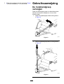
Betrieb
Hochklappen des
Stützgriffs
Klappen Sie den Stützgrif f in die hochgeklappte
Stellung, wenn die Maschine stillsteht und Sie auf und
von der Maschine steigen.
1. Klappen Sie den Stützgrif f nach oben, wie in
Bild 8 dargestellt.
g465177
Bild 8
2. Klappen Sie den Stützgrif f nach unten, wie in
Bild 9 abgebildet.
g465178
Bild 9
5

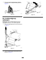
3. Stellen Sie sicher , dass der Stützgrif f vollständig
in den Langlöchern der Halterung sitzt, wie in
Bild 10 dargestellt.
g465179
Bild 10
Herunterklappen des
Stützgriffs
W ichtig: Klappen Sie den Stützgriff in die untere
Stellung, wenn Sie die Maschine bedienen.
1. Klappen Sie den Stützgrif f nach oben, wie in
Bild 1 1 abgebildet.
g465190
Bild 1 1
2. Klappen Sie den Stützgrif f vollständig nach
unten, wie in Bild 12 dargestellt.
g465191
Bild 12
6

Form No. 3465 - 898 Rev A
Kit barre de maintienT ondeuse autoportée T imeCutter
®
/T itan
®
N° de modèle 161 - 4450
Instructions de montage
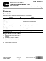
Montage
Pièces détachées
Reportez - vous au tableau ci - dessous pour vérier si toutes les pièces ont été expédiées.
Description
Qté
Utilisation
Aucune pièce requise
–
Préparation de la machine.
Poignée de maintien 1
Goupille (rainurée)
1
Rondelle (⅜")
1
Circlip
1
Assemblage de la poignée de maintien.
Support de la poignée de maintien
1
Boulon à tête hexagonale à embase(autotaraudeur – 5/16" x ¾")
2
Montage du support de la poignée de maintien.
Goupille (rainurée)
1
Rondelle (⅜")
1
Circlip
1
Montez le poignée de maintien.
Appui de la poignée 1
V is à épaulement (¼" x ½")
1
Pose de l'appui de la poignée.
Préparation de la machine1. Garez la machine sur une surface plane ethorizontale.
2. Désengagez la commande des lames.
3. Poussez les leviers de commande dedéplacement vers l'extérieur , à la positionSTATIONNEMENT .
4. Coupez le moteur et retirez la clé.
© 2023—The T oro® Company81 1 1 L yndale A venue SouthBloomington, MN 55420
Enregistrez votre produit àwww .T oro.com.
T raduction du texte d'origine (FR)
Imprimé aux États - UnisT ous droits réservés
*3465 - 898*

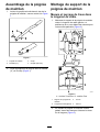
Assemblage de la poignéede maintien
1. Insérez la goupille rainurée dans le trou de lapoignée de maintien, comme montré à la Figure1.
g464941
Figure 1
1. Poignée de maintien
3. Circlip
2. Rondelle (⅜") 4. Goupille (rainurée)
2. Fixez la goupille sur la poignée avec la rondelle(⅜") et le circlip ( Figure 1 ).
Montage du support de lapoignée de maintien
Mesure et perçage de trous dansle longeron de cadre
1. Maintenez le support de la poignée de maintiencontre le longeron de cadre gauche, etpositionnez - le en vous aidant des mesures pourvotre modèle particulier ( Figure 2 ).
g464996
Figure 2
A : modèles T imeCutter . B : modèles T itan.
1. Support de la poignée demaintien
3. 1 13 mm
2. Longeron de cadre gauche 4. 146 mm
2. En utilisant la poignée de maintien commegabarit, tracez des marques à travers les troussur le longeron ( Figure 3 ).
2

g465023
Figure 3
1. Marquer et percer un trouici
2. Longeron de cadre gauche
3. Percez des trous aux emplacements marquésavec un foret (9/32"), comme montré à la Figure3.
A TTENTION
Des débris peuvent être projetés dansles yeux et causer des blessures encas d'utilisation d'une perceuse sansprotection oculaire adaptée.
Portez toujours une protection oculairepour les opérations de perçage.
Fixation du support sur lelongeron de cadre
Fixez le support sur le côté du longeron de cadregauche à l'aide de 2 boulons autotaraudeurs à têtehexagonale à embase.
g465027
Figure 4
1. Boulon à tête hexagonale à embase (autotaraudeur –5/16" x ¾")
3

Montage de la poignée demaintien
1. Alignez le trou inférieur de la poignée demaintien sur la fente fermée du support de lapoignée, comme montré à la Figure 5 .
g465144
Figure 5
Modèle T imeCutter montré
1. Rondelle (⅜") 3. Goupille (rainurée)
2. Circlip
2. Insérez la goupille rainurée dans la fente dusupport et le trou de la poignée de maintien(Figure 5 ).
3. Fixez la goupille au support et à la poignée avecla rondelle (⅜") et le circlip ( Figure 5 ).
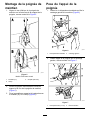
Pose de l'appui de lapoignée
1. Retirez la vis à épaulement existante qui xe lecarénage gauche à la machine ( Figure 6 ).
g465175
Figure 6
1. V is à épaulement existante
2. Carénage gauche
2. Placez l'appui de la poignée sur le carénagegauche, comme montré à la Figure 7 .
g465176
Figure 7
1. V is à épaulement (¼" x ½")
2. Étrier de xation
4

3. Fixez l'appui sur le carénage ( Figure 7 ) avec lavis à épaulement (¼" x ½") prise dans le kit.
Utilisation
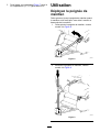
Déployez la poignée demaintien
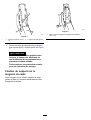
Faites pivoter et levez la poignée de maintien quandla machine est à l'arrêt pour vous aider à monter oudescendre de la machine.
1. Faites pivoter la poignée de maintien, commemontré à la Figure 8 .
g465177
Figure 8
2. Enfoncez la poignée de maintien, commemontré à la Figure 9 .
g465178
Figure 9
5

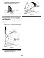
3. Assurez - vous que la poignée de maintien estcomplètement engagée dans les fentes dusupport, comme montré à la Figure 10 .
g465179
Figure 10
Rangement de la poignéede maintien
Important: Faites pivoter la poignée de maintienen position de rangement quand vous utilisez lamachine.
1. Levez la poignée de maintien comme montré àla Figure 1 1 .
g465190
Figure 1 1
2. Faites pivoter et baissez la poignée de maintien,comme montré à la Figure 12 .
g465191
Figure 12
6
Seite wird geladen ...
Seite wird geladen ...
Seite wird geladen ...
Seite wird geladen ...
Seite wird geladen ...
Seite wird geladen ...
Seite wird geladen ...
Seite wird geladen ...
-
 1
1
-
 2
2
-
 3
3
-
 4
4
-
 5
5
-
 6
6
-
 7
7
-
 8
8
-
 9
9
-
 10
10
-
 11
11
-
 12
12
-
 13
13
-
 14
14
-
 15
15
-
 16
16
-
 17
17
-
 18
18
-
 19
19
-
 20
20
-
 21
21
-
 22
22
-
 23
23
-
 24
24
-
 25
25
-
 26
26
-
 27
27
-
 28
28


Toro Assist Bar Kit, TimeCutter/Titan Riding Mower Installationsanleitung
- Typ
- Installationsanleitung
in anderen Sprachen
Verwandte Artikel
-
Toro LED Light Kit, TimeCutter HD Riding Mower Installationsanleitung
-
-
-
-
Toro E-Z Vac Complete Twin Bagger, TimeCutter HD Riding Mower Benutzerhandbuch
-
-
-
Toro 127 cm TimeCutter MX 5075T Zero Turn Mower 74695 Benutzerhandbuch
-
Toro PowerPlex 61cm 40V MAX Hedge Trimmer Benutzerhandbuch