SICK AFS/AFM60 EtherNet/ IP absolute encoders Mounting instructions
- Typ
- Mounting instructions

DEUTSCH DEUTSCHDEUTSCH DEUTSCH
AFS/AFM60 EtherNet/IP Absolut-Encoder sind nach den anerkannten
Regeln der Technik hergestellte Messgeräte.
▸
Der Anbau des Encoders ist von einem Fachmann mit Kenntnissen
in Elektrik und Feinmechanik vorzunehmen.
▸
Der Encoder darf nur zu dem seiner Bauart entsprechenden Zweck
verwendet werden.
Sicherheitshinweise
▸
Beachten Sie die für Ihr Land gültigen berufsgenossenschaftlichen
Sicherheits- und Unfallverhütungsvorschriften.
▸
Schalten Sie die Spannung bei allen von der Montage betroffenen
Geräte/Maschinen und Anlagen ab.
▸
Elektrische Verbindungen zum Encoder nie bei eingeschalteter Span-
nung herstellen bzw. lösen, dies kann zu Gerätedefekt führen.
▸
Schläge auf die Welle bzw. Spannzange vermeiden.
Abschirmung gemäß EtherNet/IP-Spezikation
Es wird empfohlen, geschirmte Leitungen zu verwenden und den
Schirm beidseitig aufzulegen. Um ein Optimum an Schirmeektivität zu
erreichen und zu verhindern, dass Masseausgleichsströme über den
Schirm ießen, ist Folgendes zu beachten:
▸
Es muss sichergestellt sein, dass eine gute elektrische Verbindung
zwischen dem Metallgehäuse des Encoders und den geerdeten Me-
tallteilen der Anlage/Maschine vorhanden ist. Dies wird gewöhnlich
durch die metallische Verbindung über den Encoderflansch erreicht.
▸
Falls die angewandte Befestigungsweise keine gut leitende elektri-
sche Verbindung aufweist, müssen zusätzliche Maßnahmen in Form
eines Erdungskabels getroffen werden.
Anschluss an das Netzwerk (Port 1 oder Port 2)
▸
Anschluss direkt über Rundschraubsystem M12.
▸
Im Auslieferungszustand ist der Port 2 mit einer aufgeschraubten
Kunststoffkappe versehen.
Anzugsmoment 0,4 Nm
▸
Die Schutzart IP 65 (Welle), IP 67 (Gehäuse) wird nur mit aufge-
schraubten Steckern oder Kunststoffkappen erreicht.
Installationshinweise zur Spannungsversorgung
Die Zuführung der Versorgungsspannung erfolgt im Allgemeinen über
eine separate Leitung und wird nicht als Linienstruktur ausgelegt. Soll
für die Spannungsversorgung ebenfalls eine Struktur als Bus verwen-
det werden, gilt folgende Einschränkung:
a
Max. Stromfluss über die Stecker bzw. Anschlussleiste im Bus-
Anschlussadapter ist begrenzt auf 2 A.
a
Max. Anzahl der Encoder in Reihenschaltung beträgt 10.
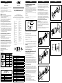
Rundschraubsystem M12
Anschluss über 3 x Rundschraubsystem M12.
Pinbelegung
EtherNet/IP Pinout
Port 1 und 2 PIN Signal Farbe der Adern
2
1
3
4
1 TXD+ Weiß/orange
3 TXD– Orange
2 RXD+ Weiß/grün
4 RXD– Grün
Versorgungsspannung PIN Signal Farbe der Adern
1
2
4
3
1 V
CC
Braun
2
Warnung!
Nicht benutzen.
Weiß
3 GND Blau
4
Warnung!
Nicht benutzen.
Schwarz
LED Statusinformation
Der Encoder verfügt über 5 LED’s, die Statusinformationen und Fehler-
informationen anzeigen.
Net
Mod
Link 1
Link 2
Encoder
Modul Status LED Kurzbeschreibung
OFF Keine Versorgungsspannung
Grün Gerät betriebsbereit
Grün blinkend Standby
Rot blinkend Geringfügiger Fehler
Rot Schwerwiegender Fehler
Grün/rot blinkend Selbsttest
AFS/AFM60 EtherNet/IP Geräte-
handling im Netzwerk
Sehr geehrter Kunde,
bitte downloaden Sie die Betriebsanleitung und das EDS-File des AFS/
AFM60 EtherNet/IP von unserer Homepage www.sick.com. Hierzu
geben Sie bitte die siebenstellige Artikelnummer Ihres Encoders direkt
in das Feld „Suchen“ auf der Startseite ein. Klicken Sie dann auf das
entsprechende Suchergebnis und Sie werden zu sämtlichen Informati-
onen und Dateien für Ihr Gerät weitergeleitet.
Folgende Encodermerkmale können auch über die Hardware kongu-
riert werden:
▸
IP-Adresse
▸
Presetfunktion
Um eine dieser Funktionen ausführen zu können, sind folgende Maß-
nahmen erforderlich
▸
Schraubkappe auf der Encoderrückseite entfernen
GND
10–30 V DC
WARNING
DO NOT
USE
x10
x100 x1
Net
Mod
Link 1
Link 2
Port 1Port 2
Encoder
a
0
9
8
7
6
5
4
3
2
1
0
9
8
7
6
5
4
3
2
1
9
8
7
6
5
4
3
2
1
Dec-Switches
Drehschalter für IP-Adresse, Einerstelle, Zehnerstelle und Hunderter-
stelle
▸
Adressvergabebereich von 1–254
Beispiel: voreingestellte IP-Adresse:
192.168.1.123 (die letzten 3 Stellen sind vom Anwender frei wählbar)
Dec-Switch x 1 = Einerstelle > 7
Dec-Switch x 10 = Zehnerstelle > 5
Dec-Switch x 100 = Hunderterstelle > 1
192.168.1.157
a
Achtung: bei Dec-Switch-Stellung „888“ und erneutem Einschalten
des Encoders, wird dieser auf die Werkseinstellung zurückgesetzt.
Preset-Taster Hardware (Software siehe Handbuch
8014212)
Der Encoder wird auf einen speziellen, vordenierten Wert eingestellt,
wenn die PRESET-Funktion durch Drücken des Preset-Knopfes ausge-
führt wird. Der Defaultwert ab Werk ist null (0).
Schraubkappe wieder montieren.
Anzugsmoment Schraubkappe: 0,8 Nm
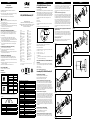
Montage AFS/AFM60 EtherNet/IP
Encoder mit Servoansch
Bei dieser Flanschausführung gibt es 2 Anbaumöglichkeiten:
▸
Über die 3 flanschseitigen Gewindebohrungen.
▸
Mit Servoklammern an der Servonut.
Anbau über anschseitige Gewindebohrungen (Bild 1)
Kundenseitige Antriebswelle blockieren. Kupplung (1) am Encoder
montieren; darauf achten, dass diese nicht am Encoder-Flansch streift.
Encoder mit montierter Kupplung (1) auf Antriebswelle und Zentrier-
satz (2) aufschieben. Encoder mit 3 Schrauben M4 (3) befestigen.
Kupplung (1) auf der Antriebswelle befestigen. Darauf achten, dass die
Kupplung keiner axialen Spannung ausgesetzt wird. Elektrische Verbin-
dung bei abgeschalteter Spannung herstellen. Spannung einschalten
und Funktion des Encoders prüfen.
Anbau mit Servoklammern (Bild 2)
Kundenseitige Antriebswelle blockieren. Kupplung (1) am Encoder
montieren; darauf achten, dass sie nicht am Encoder-Flansch streift.
Servoklammern (2) mit Schrauben M4 (3) montieren. Schrauben nicht
festziehen, Servoklammern so verdrehen, dass der Encoder-Flansch in
die Zentrierung geschoben werden kann. Encoder mit montierter Kupp-
lung (1) auf Antriebswelle und Zentrierung aufschieben. Servoklammer
(2) durch Drehen in die Nut einrücken und leicht festziehen. Kupplung
(1) auf Antriebswelle befestigen. Darauf achten, dass die Kupplung
keiner axialen Spannung ausgesetzt wird. Alle 3 Schrauben der
Servoklammern festziehen. Elektrische Verbindung bei abgeschalteter
Spannung herstellen.
Encoder mit Klemmansch
Bei dieser Flanschausführung gibt es 2 Anbaumöglichkeiten:
▸
Über flanschseitige Gewindebohrungen.
▸
Über Klemmung am Klemmansatz.
Anbau über anschseitige Gewindebohrungen (Bild 3)
Kupplung (1) montieren; darauf achten, dass sie nicht am Encoder-
Flansch streift. Encoder mit montierter Kupplung (1) auf Antriebswelle
und Zentrier-/Klemmsatz (3) aufschieben. Encoder mit 3 Schrauben
M4 (2) befestigen, Kupplung (1) auf der Antriebswelle befestigen. Die
Kupplung darf keinen axialen Spannungen ausgesetzt werden. Elek-
trische Verbindung bei abgeschalteter Spannung herstellen. Spannung
einschalten und Funktion des Encoders prüfen.
Anbau über den Klemmansatz (Bild 4)
Da der Klemmansatz gleichzeitig auch Zentrieransatz ist, muss die
Klemmvorrichtung so ausgebildet sein, dass beim Festklemmen
kein unzulässiger Winkel bzw. Wellenversatz entsteht. Kundenseitige
Antriebswelle blockieren. Kupplung (1) montieren; darauf achten,
dass sie beim Verdrehen der Welle nicht am Encoder-Flansch streift.
Encoder mit montierter Kupplung (1) auf Antriebswelle und Klem-
mansatz in Klemmvorrichtung (2) aufschieben. Encoder mit Schraube
(3) festklemmen. Kupplung (1) auf der Antriebswelle befestigen. Die
Kupplung darf keinen axialen Spannungen ausgesetzt werden. Elek-
trische Verbindung bei abgeschalteter Spannung herstellen. Spannung
einschalten und Funktion des Encoders prüfen.
Encoder mit Flansch für Aufsteckhohlwelle
(Bild 5 und 6)
Kundenseitige Antriebswelle blockieren. Zylinderschraube (2) am
Klemmring (1) lösen. Encoder mit Spannzange auf Antriebswelle
aufschieben. Anbauhinweis Bild 6 beachten! Momentenstütze (3) mit
4 Schrauben M3 (4) und U-Scheiben befestigen. Zylinderschraube (2)
an Klemmring (1) festziehen.
Anzugsmoment max. 1,1 Nm.
Elektrische Verbindung bei abgeschalteter Spannung herstellen. Span-
nung einschalten und Funktion des Encoders prüfen.
Bild 1
1
2
3
Bild 2
3
2
1
Bild 3
1
2
3
Bild 4
1
3
2
Bild 5
4
Bild 6
min. 15
max. 40
1
2
3
SICK Encoder
Montageanleitung
SICK Encoder
Netzwerk Status LED Kurzbeschreibung
OFF Keine Versorgungsspannung / keine IP Adresse
Grün blinkend Keine Verbindung
Grün Angeschlossen
Rot blinkend Geringfügiger Fehler
Rot Schwerwiegender Fehler
Grün/ rot blinkend Selbsttest
Encoder Status LED Kurzbeschreibung
OFF Keine Versorgungsspannung
Grün blinkend Falscher Parameter
Grün Gerät betriebsbereit
Rot blinkend Geringfügiger Fehler
Rot Schwerwiegender Fehler
Grün/ rot blinkend Selbsttest
Link 1 Status LED Kurzbeschreibung
OFF Keine Verbindung / Versorgungsspannung aus
Grün leuchtend Link
Gelb Anschluss gestört
Grün blinkend Anschluss aktiv
Gelb blinkend Kollision
Link 2 Status LED Kurzbeschreibung
OFF Keine Verbindung / Versorgungsspannung aus
Grün leuchtend Link
Gelb Anschluss gestört
Grün blinkend Anschluss aktiv
Gelb blinkend Kollision
8014464/12XB/2019-03-18 ∙ RA_07
AFS/AFM60 EtherNet/IP
SICK STEGMANN GmbH
Postfach 1560 · D-78156 Donaueschingen
Dürrheimer Straße 36 · D-78166 Donaueschingen
Telefon: +49 (0) 771 80 70 · Telefax +49 (0) 771 80 71 00
www.sick.com · [email protected]
BZ int48
Please find detailed addresses and further locations in all major industrial
nations at www.sick.com
Australia
Phone +61 (3) 9457 0600
Austria
Phone +43 (0) 2236 62288-0
Belgium/Luxembourg
Phone +32 (0) 2 466 55 66
Brazil
Phone +55 11 3215-4900
Canada
Phone +1 905.771.1444
Czech Republic
Phone +420 2 57 91 18 50
Chile
Phone +56 (2) 2274 7430
China
Phone +86 20 2882 3600
Denmark
Phone +45 45 82 64 00
Finland
Phone +358-9-25 15 800
France
Phone +33 1 64 62 35 00
Germany
Phone +49 (0) 2 11 53 01
Hong Kong
Phone +852 2153 6300
Hungary
Phone +36 1 371 2680
India
Phone +91-22-6119 8900
Israel
Phone +972-4-6881000
Italy
Phone +39 02 27 43 41
Japan
Phone +81 3 5309 2112
Malaysia
Phone +603-8080 7425
Mexico
Phone +52 (472) 748 9451
Netherlands
Phone +31 (0) 30 229 25 44
New Zealand
Phone +64 9 415 0459
Norway
Phone +47 67 81 50 00
Poland
Phone +48 22 539 41 00
Romania
Phone +40 356-17 11 20
Russia
Phone +7 495 283 09 90
Singapore
Phone +65 6744 3732
Slovakia
Phone +421 482 901 201
Slovenia
Phone +386 591 78849
South Africa
Phone +27 (0)11 472 3733
South Korea
Phone +82 2 786 6321
Spain
Phone +34 93 480 31 00
Sweden
Phone +46 10 110 10 00
Switzerland
Phone +41 41 619 29 39
Taiwan
Phone +886-2-2375-6288
Thailand
Phone +66 2 645 0009
Turkey
Phone +90 (216) 528 50 00
United Arab Emirates
Phone +971 (0) 4 88 65 878
United Kingdom
Phone +44 (0)17278 31121
USA
Phone +1 800.325.7425
Vietnam
Phone +65 6744 3732
Irrtümer und Änderungen vorbehalten.

ENGLISH ENGLISHENGLISH ENGLISH
AFS/AFM60 EtherNet/IP absolute encoders are state-of-the-art
measuring instruments.
▸
The encoder must be installed by trained personnel with knowledge
of electrical engineering and precision engineering.
▸
The encoder must only be used for its intended purpose.
Safety advice
▸
Observe the professional safety and accident prevention regulations
applicable to your country.
▸
Switch off the voltage to all devices/machines and systems affected
by the installation process.
▸
Never electrically connect or disconnect the encoder with the voltage
switched on, this may lead to damage to the unit.
▸
Avoid striking the shaft or collet.
Shielding acc. to EtherNet/IP specication
We recommend the use of shielded cables with the shield connected
at both ends. To achieve optimum screening eectiveness and to
prevent mass equalisation currents from owing across the screen,
note the following:
▸
It must be ensured that there is a good electrical connection
between the metal housing of the encoder and the earthed metal
parts of the system/machine. This is usually achieved by the metallic
connection across the encoder flange.
▸
If the fixing method used does not have a well-conducting electrical
connection, additional measures in the form of an earthing cable
must be taken.
Connection to the network (Port 1 or Port 2)
▸
Direct connection via M12 screw-in system.
▸
On delivery, Port 2 is provided with a screw-on plastic cap.
Tightening torque 0.4 Nm
▸
Enclosure rating IP 65 (shaft), IP 67 (housing) is only achieved when
plugs or plastic caps are screwed on.
Installation notes: voltage supply
The supply voltage is generally supplied via a separate line and is
not designed as a line structure. If, for the voltage supply, the same
cabling arrangement as used by the bus is implemented, the following
limitation applies:
a
Max. current flow across the plugs or terminal block in the bus link
adapter is limited to 2 A.
a
Max. number of encoders (series connection) is 10.
Screw-in system M12
Connection via 3 x screw-in system M12.
Allocation
EtherNet/IP Pinout
Port 1 and 2 PIN Signal Color of wires
2
1
3
4
1 TXD+ White/orange
3 TXD– Orange
2 RXD+ White/green
4 RXD– Green
Voltage supply PIN Signal Color of wires
1
2
4
3
1 V
CC
Brown
2
Warning!
Do not use.
White
3 GND Blue
4
Warning!
Do not use.
Black
LED status information
The encoder has 5 LEDs that show status information and error
information.
Net
Mod
Link 1
Link 2
Encoder
Module status LED Brief description
OFF No voltage supply
Green Device ready for operation
Green, blinking Standby
Red, blinking Minor error
Red Serious error
Green/red, blinking Self-test
AFS/AFM60 EtherNet/IP, device
handling in the network
Dear valued customer,
please download the operating instructions and the EDS le for the AFS/
AFM60 EtherNet/IP from our homepage www.sick.com. For this, please
enter the seven-digit part number of your encoder directly in the eld
“Search” on the welcome page. Then please click on the searching result
and you will be forwarded to all information and les for your product.
The following encoder features can also be congured via the
hardware:
▸
IP address
▸
Preset function
The following measures are necessary in order to run one of these
functions
▸
Remove screw-on cap from the back of the encoder
GND
10–30 V DC
WARNING
DO NOT
USE
x10
x100 x1
Net
Mod
Link 1
Link 2
Port
1P
ort 2
Encoder
a
0
9
8
7
6
5
4
3
2
1
0
9
8
7
6
5
4
3
2
1
9
8
7
6
5
4
3
2
1
Dec. switches
Rotary switches for IP address, ones, tens and hundreds
▸
Address input range from 1–254
Example: preset IP address:
192.168.1.123 (the nal three places are freely selectable by user)
Dec. switch x 1 = ones > 7
Dec. switch x 10 = tens > 5
Dec. switch x 100 = hundreds > 1
192.168.1.157
a
Please note: If encoder is restarted with dec. switch set to “888” it
will be reset to the default settings.
Preset button hardware (see manual 8014213 for
software)
The encoder is set to a special pre-dened value when the PRESET
function is activated by pressing the Preset button. The works default
value is zero (0).
Remount screw cap.
Screw cap tightening torque: 0.8 Nm
Assembly AFS/AFM60 EtherNet/IP
Encoders with servo ange
This ange design oers two installation options:
▸
Via the 3 threaded holes on the flange side.
▸
With servo clamps on the servo groove.
Installation via threaded holes on the ange side (Figure 1)
Lock the drive shaft on the application side. Mount the coupling (1)
on the encoder; ensure that it does not touch the encoder ange.
Push the encoder, with mounted coupling (1), onto the drive shaft
and mounting spigot into the centring recess (2). Fix the Encoder
with 3 x M4 screws (3). Fix the coupling (1) to the drive shaft. The
coupling must not be subjected to any axial stresses. Make the electric
connections with the voltage switched o. Switch on the voltage and
check the operation of the encoder.
Installation with servo clamps (Figure 2)
Lock the drive shaft on the application side. Mount the coupling (1) on
the encoder; ensure that it does not touch the encoder ange. Mount
the servo clamps (2) with M4 screws (3). Do not tighten screws, rotate
the servo clamps such that the encoder ange can be pushed into
the centring recess. Push the encoder, with mounted coupling (1),
onto drive shaft and centring recess. Place the servo clamp (2), into
the groove, and tighten lightly. Fix the coupling (1) to the drive shaft.
The coupling must not be subjected to any axial stresses. Tighten all
3 screws of the servo clamps. Make the electric connections with the
voltage switched o. Switch on the voltage and check the operation of
the encoder.
Encoders with face mount ange
This ange design oers two installation options:
▸
Via the threaded holes on the flange side.
▸
By clamping the mounting spigot.
Installation via the threaded holes on the ange side (Figure 3)
Lock the drive shaft on the application side. Mount the coupling (1);
ensure that it does not touch the encoder ange. Push the encoder,
with mounted coupling (1), onto the drive shaft and centring/clamping
arrangement (3). Fix the encoder with 3 x M4 screws (2), x the
coupling (1) to the drive shaft. The coupling must not be subjected to
any axial stresses. Make the electrical connections with the voltage
switched o. Switch on the voltage and check the operation of the
encoder.
Installation via the mounting spigot (Figure 4)
Since the mounting spigot is also the means of centring, the clamping
device must be constructed such that clamping rmly does not lead to
an invalid angle or shaft oset. Lock the drive shaft on the application
side. Mount the coupling (1); ensure that, when the shaft is rotated, it
does not touch the encoder ange. Push the encoder, with mounted
coupling (1), onto the drive shaft, and the mounting spigot into the
clamping device (2). Clamp the encoder with the screw (3). Fix the
coupling (1) on the drive shaft. The coupling must not be subjected to
any axial stresses. Make the electrical connections with the voltage
switched o. Switch on the voltage and check the operation of the
encoder.
Encoders with stator coupling for blind hollow shaft
(Figure 5 and 6)
Lock the drive shaft on the application side. Loosen the hexagonal
screw (2) on the clamping ring (1). Push the encoder and collet onto
the drive shaft. Take note of installation gure 6. Fix the stator coupling
(3) with 4 x M3 screws (4) and washers. Firmly tighten the hexagonal
screw (2) on the clamping ring (1).
Tightening torque 1.1 Nm.
Make the electrical connections with the voltage switched o. Switch
on the voltage and check the operation of the encoder.
Figure 1
1
2
3
Figure 2
3
2
1
Figure 3
1
2
3
Figure 4
1
3
2
Figure 5
4
Figure 6
min. 15
max. 40
1
2
3
SICK encoders
Mounting instructions
SICK encoders
Network status LED Brief description
OFF No voltage supply / no IP address
Green, blinking No connection
Green Connected
Red, blinking Minor error
Red Serious error
Green/red, blinking Self-test
Encoder status LED Brief description
OFF No voltage supply
Green, blinking Wrong parameter
Green Device ready for operation
Red, blinking Minor error
Red Serious error
Green/red, blinking Self-test
Link 1 status LED Brief description
OFF No connection / voltage supply o
Green Link
Yellow Connection interrupted
Green, blinking Connection active
Yellow, blinking Collision
Link 2 status LED Brief description
OFF No connection / voltage supply o
Green Link
Yellow Connection interrupted
Green, blinking Connection active
Yellow, blinking Collision
AFS/AFM60 EtherNet/IP
SICK STEGMANN GmbH
PO Box 1560 · D-78156 Donaueschingen, Germany
Dürrheimer Straße 36 · D-78166 Donaueschingen, Germany
Phone: +49 771 80 70 · Fax: +49 771 80 71 00
www.sick.com · [email protected]
BZ int48
Please find detailed addresses and further locations in all major industrial
nations at www.sick.com
Australia
Phone +61 (3) 9457 0600
Austria
Phone +43 (0) 2236 62288-0
Belgium/Luxembourg
Phone +32 (0) 2 466 55 66
Brazil
Phone +55 11 3215-4900
Canada
Phone +1 905.771.1444
Czech Republic
Phone +420 2 57 91 18 50
Chile
Phone +56 (2) 2274 7430
China
Phone +86 20 2882 3600
Denmark
Phone +45 45 82 64 00
Finland
Phone +358-9-25 15 800
France
Phone +33 1 64 62 35 00
Germany
Phone +49 (0) 2 11 53 01
Hong Kong
Phone +852 2153 6300
Hungary
Phone +36 1 371 2680
India
Phone +91-22-6119 8900
Israel
Phone +972-4-6881000
Italy
Phone +39 02 27 43 41
Japan
Phone +81 3 5309 2112
Malaysia
Phone +603-8080 7425
Mexico
Phone +52 (472) 748 9451
Netherlands
Phone +31 (0) 30 229 25 44
New Zealand
Phone +64 9 415 0459
Norway
Phone +47 67 81 50 00
Poland
Phone +48 22 539 41 00
Romania
Phone +40 356-17 11 20
Russia
Phone +7 495 283 09 90
Singapore
Phone +65 6744 3732
Slovakia
Phone +421 482 901 201
Slovenia
Phone +386 591 78849
South Africa
Phone +27 (0)11 472 3733
South Korea
Phone +82 2 786 6321
Spain
Phone +34 93 480 31 00
Sweden
Phone +46 10 110 10 00
Switzerland
Phone +41 41 619 29 39
Taiwan
Phone +886-2-2375-6288
Thailand
Phone +66 2 645 0009
Turkey
Phone +90 (216) 528 50 00
United Arab Emirates
Phone +971 (0) 4 88 65 878
United Kingdom
Phone +44 (0)17278 31121
USA
Phone +1 800.325.7425
Vietnam
Phone +65 6744 3732
8014464/12XB/2019-03-18 ∙ RA_07
Subject to change without notice.
-
 1
1
-
 2
2


SICK AFS/AFM60 EtherNet/ IP absolute encoders Mounting instructions
- Typ
- Mounting instructions
in anderen Sprachen
Verwandte Artikel
-
SICK AFS/AFM60 PROFINET Absolute Encoder Bedienungsanleitung
-
-
-
-
-
-
-
-
-