Yamaha 02R96 Bedienungsanleitung
- Kategorie
- DJ-Controller
- Typ
- Bedienungsanleitung

DIGITAL MIXING CONSOLE
EN
Owner’s ManualOwner’s Manual
Owner’s Manual
Keep This Manual For Future Reference.

WARNING: THIS APPARATUS MUST BE EARTHED
IMPORTANT
THE WIRES IN THIS MAINS LEAD ARE COLOURED IN
ACCORDANCE WITH THE FOLLOWING CODE:
GREEN-AND-YELLOW : EARTH
BLUE : NEUTRAL
BROWN : LIVE
As the colours of the wires in the mains lead of this apparatus may
not correspond with the coloured markings identifying the terminals in
your plug, proceed as follows:
The wire which is coloured GREEN and YELLOW must be
connected to the terminal in the plug which is marked by the letter E
or by the safety earth symbol or coloured GREEN and YELLOW.
The wire which is coloured BLUE must be connected to the terminal
which is marked with the letter N or coloured BLACK.
The wire which is coloured BROWN must be connected to the
terminal which is marked with the letter L or coloured RED.
* This applies only to products distributed by YAMAHA KEMBLE
MUSIC (U.K.) LTD.
FCC INFORMATION (U.S.A.)
1. IMPORTANT NOTICE: DO NOT MODIFY THIS UNIT! This product, when installed as indicated in the instructions contained in this manual, meets FCC
requirements. Modifications not expressly approved by Yamaha may void your authority, granted by the FCC, to use the product.
2. IMPORTANT: When connecting this product to accessories and/or another product use only high quality shielded cables. Cable/s supplied with this product MUST
be used. Follow all installation instructions. Failure to follow instructions could void your FCC authorization to use this product in the USA.
3. NOTE: This product has been tested and found to comply with the requirements listed in FCC Regulations, Part 15 for Class “B” digital devices. Compliance with
these requirements provides a reasonable level of assurance that your use of this product in a residential environment will not result in harmful interference with
other electronic devices. This equipment generates/uses radio frequencies and, if not installed and used according to the instructions found in the users manual, may
cause interference harmful to the operation of other electronic devices. Compliance with FCC regulations does not guarantee that interference will not occur in all
installations. If this product is found to be the source of interference, which can be determined by turning the unit “OFF” and “ON”, please try to eliminate the
problem by using one of the following measures: Relocate either this product or the device that is being affected by the interference. Utilize power outlets that are on
different branch (circuit breaker or fuse) circuits or install AC line filter/s. In the case of radio or TV interference, relocate/reorient the antenna. If the antenna lead-in
is 300 ohm ribbon lead, change the lead-in to coaxial type cable. If these corrective measures do not produce satisfactory results, please contact the local retailer
authorized to distribute this type of product. If you can not locate the appropriate retailer, please contact Yamaha Corporation of America, Electronic Service
Division, 6600 Orangethorpe Ave, Buena Park, CA 90620
The above statements apply ONLY to those products distributed by Yamaha Corporation of America or its subsidiaries.
ADVARSEL!
Lithiumbatteri—Eksplosionsfare ved fejlagtig
håndtering. Udskiftning må kun ske med batteri
af samme fabrikat og type. Levér det brugte
batteri tilbage til leverandoren.
VARNING
Explosionsfara vid felaktigt batteribyte. Använd
samma batterityp eller en ekvivalent typ som
rekommenderas av apparattillverkaren.
Kassera använt batteri enligt fabrikantens
instruktion.
VAROITUS
Paristo voi räjähtää, jos se on virheellisesti
asennettu. Vaihda paristo ainoastaan
laitevalmistajan suosittelemaan tyyppiin. Hävitä
käytetty paristo valmistajan ohjeiden
mukaisesti.
• Explanation of Graphical Symbols
The lightning flash with arrowhead symbol
within an equilateral triangle is intended to
alert the user to the presence of uninsulated
“dangerous voltage” within the product’s
enclosure that may be of sufficient magni-
tude to constitute a risk of electric shock to
persons.
The exclamation point within an equilat-
eral triangle is intended to alert the user to
the presence of important operating and
maintenance (servicing) instructions in the
literature accompanying the product.
CAUTION: TO REDUCE THE RISK OF
ELECTRIC SHOCK, DO NOT REMOVE
COVER (OR BACK). NO USER-SERVICEABLE
PARTS INSIDE. REFER SERVICING TO
QUALIFIED SERVICE PERSONNEL.
CAUTION
RISK OF ELECTRIC SHOCK
DO NOT OPEN
The above warning is located on the
side of the unit.
NEDERLAND / THE NETHERLANDS
• Dit apparaat bevat een lithium batterij voor geheugen back-up.
• This apparatus contains a lithium battery for memory back-up.
• Raadpleeg uw leverancier over de verwijdering van de batterij op het
moment dat u het apparaat ann het einde van de levensduur of gelieve
dan contact op te nemen met de vertegenwoordiging van Yamaha in
uw land.
•For the removal of the battery at the moment of the disposal at the end
of life please consult your retailer or Yamaha representative office in
your country.
• Gooi de batterij niet weg, maar lever hem in als KCA.
• Do not throw away the battery. Instead, hand it in as small chemical
waste.
(lithium disposal)

Warnings
3
02R96 Version 2—Owner’s Manual
Important Information
Warnings
•Connect this unit’s power cord only to an AC outlet of the type stated in this Owner’s Man-
ual or as marked on the unit. Failure to do so is a fire and electrical shock hazard.
•Be sure to connect to an appropriate outlet with a protective grounding connection.
Improper grounding can result in electrical shock.
•Do not allow water to enter this unit or allow the unit to become wet. Fire or electrical shock
may result.
•Do not place heavy objects, including this unit, on top of the power cord. A damaged power
cord is a fire and electrical shock hazard. In particular, be careful not to place heavy objects
on a power cord covered by a carpet.
•Do not place a container with liquid or small metal objects on top of this unit. Liquid or
metal objects inside this unit are a fire and electrical shock hazard.
•This unit is equipped with a dedicated ground connection to prevent electrical shock.
Before connecting the power plug to an AC outlet, be sure to ground the unit. If the power
cord has a three-pin plug, it will provide sufficient grounding so long as the AC outlet is
grounded correctly.
•Do not scratch, bend, twist, pull, or heat the power cord. A damaged power cord is a fire
and electrical shock hazard.
•Do not remove the unit’s cover. You could receive an electrical shock. If you think internal
inspection, maintenance, or repair is necessary, contact your dealer.
•Do not modify the unit. Doing so is a fire and electrical shock hazard.
•If lightning begins to occur, turn off the power switch of the unit as soon as possible, and
unplug the power cable plug from the electrical outlet.
•If there is a possibility of lightning, do not touch the power cable plug if it is still connected.
Doing so may be an electrical shock hazard.
•Use only the included power cord for this unit. Using other types may be a fire and electrical
shock hazard.
•The 02R96 has four rear-panel slots for installing mini-YGDAI cards. For technical reasons,
certain card combinations are not supported. Before installing any cards, check the Yamaha
web site to if your card is compatible. Installing cards that are not endorsed by Yamaha may
cause electrical shock, fire, or damage to the unit.
•If the power cord is damaged (i.e., cut or a bare wire is exposed), ask your dealer for a
replacement. Using the unit with a damaged power cord is a fire and electrical shock hazard.
•If you notice any abnormality, such as smoke, odor, or noise, or if a foreign object or liquid
gets inside the unit, turn it off immediately. Remove the power cord from the AC outlet.
Consult your dealer for repair. Using the unit in this condition is a fire and electrical shock
hazard.
• Should this unit be dropped or the cabinet be damaged, turn the power switch off, remove
the power plug from the AC outlet, and contact your dealer. If you continue using the unit
without heeding this instruction, fire or electrical shock may result.
Cautions
•Keep this unit away from the following locations:
—Locations exposed to oil splashes or steam, such as near cooking stoves, humidifiers, etc.
—Unstable surfaces, such as a wobbly table or slope.
—Locations exposed to excessive heat, such as inside a car with all the windows closed, or
places that receive direct sunlight.
—Locations subject to excessive humidity or dust accumulation.

4
Important Information
02R96 Version 2—Owner’s Manual
•Hold the power cord plug when disconnecting it from an AC outlet. Never pull the cord. A
damaged power cord is a potential fire and electrical shock hazard.
•Do not touch the power plug with wet hands. Doing so is a potential electrical shock hazard.
•This unit has ventilation holes along the front underside and at the rear to prevent the inter-
nal temperature from rising too high. Do not block them. Blocked ventilation holes are a
fire hazard. In particular, do not operate the unit while it’s on its side, is upside down, or
while it’s covered with a cloth or dust sheet.
•If you are using the optional MB02R96 Peak Meter Bridge, do not hold only the MB02R96
when moving the 02R96. Otherwise, the meter brackets may be damaged, the main unit
may malfunction, or you may be injured if the unit falls.
•This unit is heavy. Use two or more people to carry it.
•When you transport or move the 02R96 with the MB02R96 attached, do not permit impact
or stress on the cable connector that connects the MB02R96 to the 02R96. Otherwise, mal-
function may occur.
•To relocate the unit, turn the power switch off, remove the power plug from the AC outlet,
and remove all connecting cables. Damaged cables may cause fire or electrical shock.
•When setting up the product, make sure that the AC outlet you are using is easily accessible.
If some trouble or malfunction occurs, immediately turn off the power switch and discon-
nect the plug from the outlet. Even when the power switch is turned off, electricity is still
flowing to the product at the minimum level. When you are not using the product for a long
time, make sure to unplug the power cord from the wall AC outlet.
•If you know you will not use this unit for a long period of time, such as when going on vaca-
tion, remove the power plug from the AC outlet. Leaving it connected is a potential fire haz-
ard.
•The inside of the unit should be cleaned periodically. Dust accumulation inside the unit
may cause malfunction and is a potential fire hazard. Consult your dealer for information
about cleaning.
•To prevent electrical shock when cleaning the unit, remove the power plug from the AC out-
let.
•Do not apply oil, grease, or contact cleaner to the faders. Doing so may cause problems with
electrical contact or fader motion.
•Do not use the headphones for a long period of time at a high or uncomfortable volume
level, since this can cause permanent hearing loss. If you experience any hearing loss or ring-
ing in the ears, consult a physician.
Operating Notes
• XLR-type connectors are wired as follows: pin 1–ground, pin 2–hot (+), and pin 3–cold (–).
•Insert TRS phone jacks are wired as follows: sleeve–ground, tip–send, and ring–return.
•The performance of components with moving contacts, such switches, rotary controls, fad-
ers, and connectors, deteriorates over time. The rate of deterioration depends on the oper-
ating environment and is unavoidable. Consult your dealer about replacing defective
components.
•Using a mobile telephone near this unit may induce noise. If noise occurs, use the telephone
away from the unit.
•If the message “WARNING Low Battery!” appears when you turn on this unit, contact your
dealer as soon as possible about replacing the internal data backup battery. The unit will still
operate correctly, but data other than the presets will be lost.
•Before replacing the batteries, back up your data to a memory card, or another unit by using
MIDI Bulk Dump.
•The digital circuits of this unit may induce a slight noise into nearby radios and TVs. If noise
occurs, relocate the affected equipment.

Interference
5
02R96 Version 2—Owner’s Manual
•When connecting D-sub cables, be sure to tighten the screws on both sides of the connector
securely. To disconnect the cable, loosen the screws completely, then remove the cable by
holding the connector part. Do not remove the plug by pulling the cable while the screws
are still attached. Otherwise, the connector may be damaged, leading to malfunction.
•When you change the wordclock settings on any device in your digital audio system, some
devices may output noise, so turn down your power amps beforehand, otherwise your
speakers may be damaged.
Interference
The 02R96 uses high-frequency digital circuits that may cause interference on radio and
television equipment located nearby. If interference is a problem, relocate the affected
equipment. Using a mobile telephone near the unit may induce noise. In this case use the
telephone away from the unit.
02R96 Exclusion of Certain Responsibility
Manufacturer, importer, or dealer shall not be liable for any incidental damages including
personal injury or any other damages caused by improper use or operation of the 02R96.
Trademarks
ADAT MultiChannel Optical Digital Interface is a trademark and ADAT and Alesis are reg-
istered trademarks of Alesis Corporation. Apogee is a trademark of Apogee Electronics, Inc.
Apple, Mac, and Power Macintosh are registered trademarks and Mac OS is a trademark of
Apple Corporation, Inc. HUI is a trademark of Mackie Designs, Inc. Intel and Pentium are
registered trademarks of Intel Corporation. Nuendo is a registered trademark of Steinberg
Media Technologies AG. Pro Tools is a trademark or registered trademark of Digidesign
and/or Avid Technology, Inc. Tascam Digital Interface is a trademark and Tascam and Teac
are registered trademarks of Teac Corporation. Microsoft and Windows are registered
trademarks of Microsoft Corporation, Inc. Waves is a trademark of Waves, Inc. Yamaha is a
trademark of Yamaha Corporation. Nuendo and Cubse SX are trademarks of Steinberg
Media Technologies GmbH. All other trademarks are the property of their respective hold-
ers and are hereby acknowledged.
Copyright
No part of the 02R96, its software, or this
Owner’s Manual
may be reproduced or distrib-
uted in any form or by any means without the prior written authorization of Yamaha Cor-
poration.
© 2003 Yamaha Corporation. All rights reserved.
Yamaha Web Site
Further information about the 02R96, related products, and other Yamaha professional
audio equipment is available on the Yamaha Professional Audio Web site at:
<http://www.yamahaproaudio.com/>.
Package Contents
• 02R96 Digital Mixing Console
• CD-ROM
•Power cord
•This manual
•Studio Manager Installation Guide
Optional Extras
•MB02R96 Peak Meter Bridge
• SP02R96 Wooden Side Panels
• mini YGDAI I/O cards

6
Important Information
02R96 Version 2—Owner’s Manual
About this Owner’s Manual
This
Owner’s Manual
covers the 02R96 Digital Mixing Console.
All the information you need in order to operate the 02R96 Digital Mixing Console is con-
tained in this manual. Use the table of contents to familiarize yourself with the manual’s
organization and to locate tasks and topics, and use the index to locate specific information.
Before diving in, it’s recommend that you read the “Operating Basics” chapter, starting on
page 43.
Each chapter of this manual discusses a specific section or function of the 02R96. The Input
and Output Channels are explained in the following chapters: “Input Channels,” “Bus
Outs,” “Aux Sends,” and “Stereo Out.” Where possible, these chapters have been organized
in order of signal flow, from input through to output.
Functions such as EQ and Delay are common to all channels. Rather than repeat the same
information over and over, these functions are explained once in the “Common Channel
Functions” chapter, which starts on page 107. The Input Channels, Bus Outs, Aux Sends,
and Stereo Out chapters contain cross-references to the relevant sections of the “Common
Channel Functions” chapter.
Conventions Used in this Manual
The 02R96 features two types of button: physical buttons that you can press (e.g., ENTER
and DISPLAY) and buttons that appear on the display pages. References to physical buttons
are enclosed in square brackets, for example, “press the [ENTER] button.” References to dis-
play page buttons are not emphasized, for example, “press the ENTER button.”
Display pages can be selected by using the [DISPLAY] buttons or the Left Tab Scroll, Right
Tab Scroll, and F1–4 buttons below the display. In order to simplify explanations, only the
[DISPLAY] button method is mentioned in the procedures. See “Selecting Display Pages”
on page 45 for details on all the ways in which pages can be selected.
Installing the 02R96
The 02R96 should be placed on a strong and stable surface, somewhere that complies with
the warnings and cautions listed in the previous sections.
New Functions in 02R96 Version 2
The following functions have been added to the 02R96 as part of the upgrade of the firm-
ware from version 1.2 to version 2.0.
Control Surface
• Encoder mode now features an assignable function, ALT LAYER, which enables you to con-
trol the channel level for all 48 channels without switching between layers.
→
page 50
•There are now 48 assignable Encoder mode parameters.
→
page 52
Input Channels
•Surround Pan supports 6.1 Surround.
→
page 85
•You can change the bus assigned to each surround pan channel.
→
page 87
•The Fader Group Master function enables you to control the overall level of the Fader group
channels simultaneously while maintaining the relative level balance of each channel.
→
page 80
•The Mute Group Master function enables you to mute all channels in a Mute group simul-
taneously.
→
page 79
•The on/off status of the Follow Pan button is reflected in the pan and Surround Pan settings.
→
page 82

New Functions in 02R96 Version 2
7
02R96 Version 2—Owner’s Manual
Aux Sends
•You can exclude channels from Aux Sends (Mix Minus).
→
page 104
•You can copy the channel fader positions to Aux Sends.
→
page 104
•You can set all Send levels to nominal simultaneously.
→
page 99
•If an Aux Send is set to pre-fader, you can set the Pre point before or after the [ON] button.
→
page 99
Common Channel Functions
•Input and Output Channel Meter pages indicate the gain reduction being applied by the
Gate and Compressor.
→
page 108
•You can select whether the Input Channel’s Pan setting is used when the Input Channel Solo
signal is set to Pre Fader.
→
page 121
•Raising the channel faders for soloed Channels from –
∞
can unsolo the Channels.
→
page 121
•The AUX SELECT [AUX 1]–[AUX 8] buttons enable you to solo or unsolo Aux Sends.
→
page 121
•The Fader Group Master function enables you to control the overall level of the Fader group
channels simultaneously while maintaining the relative level balance of each channel.
→
page 127
•The Mute Group Master function enables you to mute all channels in a Mute group simul-
taneously.
→
page 129
Monitor
•The level of the Surround Monitor can be reset to 85dB SPL.
→
page 138
•A new parameter has been added to Base Management on the Surround Monitor Setup
page.
→
page 140
•Surround Monitor is also available when Surround mode is set to Stereo.
•You can simultaneously select BUS and SLOT on the Surround Monitor page.
•You can select from Slot Channel 9 through Channel 16 as Surround Monitor signal sources.
•You can simultaneously select 2TRD, D2, D3, A1, or A2, and STEREO, ASSIGN1, or
ASSIGN2 as Control Monitor signal sources.
•You can select the Talkback mic signal as the Studio Monitor source.
→
page 142
Internal Effects and Plug-ins
•You can add optional Add-On Effects to the preset effects.
→
page 157
Scene Memory
•You can globally apply the Fade Time setting to all scenes.
→
page 166
•You can globally apply the Recall Safe setting to all scenes.
→
page 167
•Any channel or parameter settings in the current scene can be copied and pasted into other
scenes.
→
page 168
•You can select more parameters for the Recall Safe function.
→
page 167
Automix
•You can insert the current mix parameters in a region specified in the Automix data.
→
page 180
•Touching the faders can punch parameter values in and out if the corresponding OVER-
WRITE button is set to on.
→
page 171
•A parameter related to timecode synchronization has been added.
→
page 234

8
Important Information
02R96 Version 2—Owner’s Manual
Remote Control
•The Joystick or the controls in the SELECTED CHANNEL section enable you to control Pro
To ols Surround Pan settings.
•The USER DEFINED KEYS enable you to switch windows in the included Studio Manager
application software.
Other Functions
•A user-assignable layer enables you to assign Channels to Remote layer targets.
→
page 228
•You can also select General DAW (for DAW software that supports the Pro Tools protocol)
or Cubase SX as the target for a Remote layer.
→
page 219
•Yamaha’s proprietary Advanced DAW protocol has been added to Nuendo, Cubase SX, and
General DAW. This enables you to control these devices using the 02R96’s SELECTED
CHANNEL section. (Controllable functions vary depending on the DAW software and ver-
sion you are using.)
•You can now assign any of 174 functions to the USER DEFINED KEYS.
→
page 238
•You can assign the selected channels to a Fader or Mute group using the USER DEFINED
KEYS.
→
page 238
•An Operation Lock function prevents unintentional edits and uses a password to restrict
access to panel operation.
→
page 235
•The Oscillator can output sine wave signals with different frequencies to the L and R chan-
nels and odd and even buses.
→
page 234
•You can set the Auto Direct Out On check box so that if you change a channel’s Direct Out
destination, the channel Direct Out will automatically be enabled.
→
page 231
•You can set the Routing ST Pair Link check box so that the routing from paired Channels to
the Stereo Bus is linked.
→
page 231
* This applies only to products distributed by YAMAHA CORPORATION OF AMERICA. (mercury)
This product contains a high intensity lamp that contains a small amount of mercury. Disposal of this material
may be regulated due to environmental considerations. For disposal information in the United States, refer to
the Electronic Industries Alliance web site: www.eiae.org
* This applies only to products distributed by
YAMAHA CORPORATION OF AMERICA.
COMPLIANCE INFORMATION STATEMENT
(DECLARATION OF CONFORMITY PROCEDURE)
Responsible Party : Yamaha Corporation of America
Address : 6600 Orangethorpe Ave., Buena Park, Calif. 90620
Telephone : 714-522-9011
Type of Equipment : Digital Mixing Console
Model Name : 02R96
This device complies with Part 15 of the FCC Rules.
Operation is subject to the following two conditions:
1) this device may not cause harmful interference, and
2) this device must accept any interference received including interference
that may cause undesired operation.
See user manual instructions if interference to radio reception is sus-
pected.
(FCC DoC)
* This applies only to products distributed by YAMAHA CORPORATION OF AMERICA. (Perchlorate)
This product contains a battery that contains perchlorate material.
Perchlorate Material—special handling may apply,
See www.dtsc.ca.gov/hazardouswaste/perchlorate.

Contents
9
02R96 Version 2—Owner’s Manual
Contents
1 Welcome . . . . . . . . . . . . . . . . . . . . . . . . . . . . . . . . 16
2 Control Surface & Rear Panel . . . . . . . . . . . . . . . . 19
Control Surface . . . . . . . . . . . . . . . . . . . . . . . . . . . . . . . . . . . . . . . . . . . . . . . . . . . . . 19
Rear Panel . . . . . . . . . . . . . . . . . . . . . . . . . . . . . . . . . . . . . . . . . . . . . . . . . . . . . . . . . 37
3 Operating Basics . . . . . . . . . . . . . . . . . . . . . . . . . . 43
Connecting the Power Cord . . . . . . . . . . . . . . . . . . . . . . . . . . . . . . . . . . . . . . . . . . . 43
Turning On & Off the 02R96 . . . . . . . . . . . . . . . . . . . . . . . . . . . . . . . . . . . . . . . . . . 43
About the Display . . . . . . . . . . . . . . . . . . . . . . . . . . . . . . . . . . . . . . . . . . . . . . . . . . . 44
Selecting Display Pages . . . . . . . . . . . . . . . . . . . . . . . . . . . . . . . . . . . . . . . . . . . . . . . 45
Display Parameter Boxes . . . . . . . . . . . . . . . . . . . . . . . . . . . . . . . . . . . . . . . . . . . . . 45
Parameter Windows . . . . . . . . . . . . . . . . . . . . . . . . . . . . . . . . . . . . . . . . . . . . . . . . . 46
Confirmation Messages . . . . . . . . . . . . . . . . . . . . . . . . . . . . . . . . . . . . . . . . . . . . . . 46
Title Edit Window . . . . . . . . . . . . . . . . . . . . . . . . . . . . . . . . . . . . . . . . . . . . . . . . . . . 46
Selecting Layers . . . . . . . . . . . . . . . . . . . . . . . . . . . . . . . . . . . . . . . . . . . . . . . . . . . . . 47
Selecting Channels . . . . . . . . . . . . . . . . . . . . . . . . . . . . . . . . . . . . . . . . . . . . . . . . . . . 48
Selecting Fader Modes . . . . . . . . . . . . . . . . . . . . . . . . . . . . . . . . . . . . . . . . . . . . . . . 49
Selecting Encoder Modes . . . . . . . . . . . . . . . . . . . . . . . . . . . . . . . . . . . . . . . . . . . . . 50
Assigning Parameters to the ENCODER MODE Assign Buttons . . . . . . . . . . . . . 51
4 Analog I/O & the AD Input Section . . . . . . . . . . . 53
AD Input Section . . . . . . . . . . . . . . . . . . . . . . . . . . . . . . . . . . . . . . . . . . . . . . . . . . . . 53
Stereo Out . . . . . . . . . . . . . . . . . . . . . . . . . . . . . . . . . . . . . . . . . . . . . . . . . . . . . . . . . 54
Control Room Monitor Out . . . . . . . . . . . . . . . . . . . . . . . . . . . . . . . . . . . . . . . . . . 54
Studio Monitor Out . . . . . . . . . . . . . . . . . . . . . . . . . . . . . . . . . . . . . . . . . . . . . . . . . 54
Omni Outs . . . . . . . . . . . . . . . . . . . . . . . . . . . . . . . . . . . . . . . . . . . . . . . . . . . . . . . . . 54
2TR Analog INs . . . . . . . . . . . . . . . . . . . . . . . . . . . . . . . . . . . . . . . . . . . . . . . . . . . . . 54
5 Digital I/O & Cascading . . . . . . . . . . . . . . . . . . . . 55
Wordclocks . . . . . . . . . . . . . . . . . . . . . . . . . . . . . . . . . . . . . . . . . . . . . . . . . . . . . . . . 55
2TR Digital Outs . . . . . . . . . . . . . . . . . . . . . . . . . . . . . . . . . . . . . . . . . . . . . . . . . . . . 57
2TR Digital Ins . . . . . . . . . . . . . . . . . . . . . . . . . . . . . . . . . . . . . . . . . . . . . . . . . . . . . . 58
2TR In Sampling Rate Conversion . . . . . . . . . . . . . . . . . . . . . . . . . . . . . . . . . . . . . 58
Slot I/O . . . . . . . . . . . . . . . . . . . . . . . . . . . . . . . . . . . . . . . . . . . . . . . . . . . . . . . . . . . . 59
Dithering Digital Outputs . . . . . . . . . . . . . . . . . . . . . . . . . . . . . . . . . . . . . . . . . . . . 62
Monitoring Digital Input Channel Status . . . . . . . . . . . . . . . . . . . . . . . . . . . . . . . . 62
Cascading Consoles . . . . . . . . . . . . . . . . . . . . . . . . . . . . . . . . . . . . . . . . . . . . . . . . . . 63
6 Input & Output Patching . . . . . . . . . . . . . . . . . . . 66
Input Patching . . . . . . . . . . . . . . . . . . . . . . . . . . . . . . . . . . . . . . . . . . . . . . . . . . . . . . 66
Output Patching . . . . . . . . . . . . . . . . . . . . . . . . . . . . . . . . . . . . . . . . . . . . . . . . . . . . 68
Naming Input & Output Ports . . . . . . . . . . . . . . . . . . . . . . . . . . . . . . . . . . . . . . . . . 71
Patch Select Window . . . . . . . . . . . . . . . . . . . . . . . . . . . . . . . . . . . . . . . . . . . . . . . . . 71
Patching with the Encoders . . . . . . . . . . . . . . . . . . . . . . . . . . . . . . . . . . . . . . . . . . . 72

10
Contents
02R96 Version 2—Owner’s Manual
7 Input Channels . . . . . . . . . . . . . . . . . . . . . . . . . . . . 73
Patching Input Channels . . . . . . . . . . . . . . . . . . . . . . . . . . . . . . . . . . . . . . . . . . . . . 73
Metering Input Channels . . . . . . . . . . . . . . . . . . . . . . . . . . . . . . . . . . . . . . . . . . . . . 73
Reversing the Signal Phase . . . . . . . . . . . . . . . . . . . . . . . . . . . . . . . . . . . . . . . . . . . . 73
Gating Input Channels . . . . . . . . . . . . . . . . . . . . . . . . . . . . . . . . . . . . . . . . . . . . . . . 74
Attenuating Input Channels . . . . . . . . . . . . . . . . . . . . . . . . . . . . . . . . . . . . . . . . . . 75
EQ’ing Input Channels . . . . . . . . . . . . . . . . . . . . . . . . . . . . . . . . . . . . . . . . . . . . . . . 75
Grouping Input Channel EQs . . . . . . . . . . . . . . . . . . . . . . . . . . . . . . . . . . . . . . . . . 76
Input Channel Inserts . . . . . . . . . . . . . . . . . . . . . . . . . . . . . . . . . . . . . . . . . . . . . . . . 76
Compressing Input Channels . . . . . . . . . . . . . . . . . . . . . . . . . . . . . . . . . . . . . . . . . 76
Grouping Input Channel Compressors . . . . . . . . . . . . . . . . . . . . . . . . . . . . . . . . . 77
Delaying Input Channels . . . . . . . . . . . . . . . . . . . . . . . . . . . . . . . . . . . . . . . . . . . . . 77
Muting Input Channels (ON/OFF) . . . . . . . . . . . . . . . . . . . . . . . . . . . . . . . . . . . . 77
Grouping Input Channel Mutes (ON/OFF) . . . . . . . . . . . . . . . . . . . . . . . . . . . . . 78
Input Channel Mute Master . . . . . . . . . . . . . . . . . . . . . . . . . . . . . . . . . . . . . . . . . . 79
Setting Input Channel Levels . . . . . . . . . . . . . . . . . . . . . . . . . . . . . . . . . . . . . . . . . . 79
Grouping Input Channel Faders . . . . . . . . . . . . . . . . . . . . . . . . . . . . . . . . . . . . . . . 79
Group Master for Input Channel Faders . . . . . . . . . . . . . . . . . . . . . . . . . . . . . . . . 80
Routing Input Channels . . . . . . . . . . . . . . . . . . . . . . . . . . . . . . . . . . . . . . . . . . . . . . 82
Panning Input Channels . . . . . . . . . . . . . . . . . . . . . . . . . . . . . . . . . . . . . . . . . . . . . 83
Using Surround Pan . . . . . . . . . . . . . . . . . . . . . . . . . . . . . . . . . . . . . . . . . . . . . . . . . 85
Assigning Surround Channels to Buses . . . . . . . . . . . . . . . . . . . . . . . . . . . . . . . . . 87
Sending Input Channels to Aux Sends . . . . . . . . . . . . . . . . . . . . . . . . . . . . . . . . . . 90
Soloing Input Channels . . . . . . . . . . . . . . . . . . . . . . . . . . . . . . . . . . . . . . . . . . . . . . 90
Direct Outs . . . . . . . . . . . . . . . . . . . . . . . . . . . . . . . . . . . . . . . . . . . . . . . . . . . . . . . . 90
Pairing Input Channels . . . . . . . . . . . . . . . . . . . . . . . . . . . . . . . . . . . . . . . . . . . . . . 90
Viewing Input Channel Settings . . . . . . . . . . . . . . . . . . . . . . . . . . . . . . . . . . . . . . . 90
Naming Input Channels . . . . . . . . . . . . . . . . . . . . . . . . . . . . . . . . . . . . . . . . . . . . . . 90
Using the MS Stereo Microphone . . . . . . . . . . . . . . . . . . . . . . . . . . . . . . . . . . . . . . 91
8 Stereo Out . . . . . . . . . . . . . . . . . . . . . . . . . . . . . . . 92
Stereo Out Connectors . . . . . . . . . . . . . . . . . . . . . . . . . . . . . . . . . . . . . . . . . . . . . . . 92
Patching the Stereo Out to Outputs . . . . . . . . . . . . . . . . . . . . . . . . . . . . . . . . . . . . 92
Routing Input Channels to the Stereo Out . . . . . . . . . . . . . . . . . . . . . . . . . . . . . . . 92
Sending Bus Outs to the Stereo Out . . . . . . . . . . . . . . . . . . . . . . . . . . . . . . . . . . . . 92
Metering the Stereo Out . . . . . . . . . . . . . . . . . . . . . . . . . . . . . . . . . . . . . . . . . . . . . . 92
Monitoring the Stereo Out . . . . . . . . . . . . . . . . . . . . . . . . . . . . . . . . . . . . . . . . . . . 92
Attenuating the Stereo Out . . . . . . . . . . . . . . . . . . . . . . . . . . . . . . . . . . . . . . . . . . . 92
EQ’ing the Stereo Out . . . . . . . . . . . . . . . . . . . . . . . . . . . . . . . . . . . . . . . . . . . . . . . 92
Grouping Master EQs . . . . . . . . . . . . . . . . . . . . . . . . . . . . . . . . . . . . . . . . . . . . . . . . 92
Stereo Out Inserts . . . . . . . . . . . . . . . . . . . . . . . . . . . . . . . . . . . . . . . . . . . . . . . . . . . 93
Compressing the Stereo Out . . . . . . . . . . . . . . . . . . . . . . . . . . . . . . . . . . . . . . . . . . 93
Grouping Master Compressors . . . . . . . . . . . . . . . . . . . . . . . . . . . . . . . . . . . . . . . . 93
Muting the Stereo Out (ON/OFF) . . . . . . . . . . . . . . . . . . . . . . . . . . . . . . . . . . . . . 93
Grouping Master Mutes (ON/OFF) . . . . . . . . . . . . . . . . . . . . . . . . . . . . . . . . . . . . 93
Setting the Stereo Out Level . . . . . . . . . . . . . . . . . . . . . . . . . . . . . . . . . . . . . . . . . . . 93
Grouping Master Faders . . . . . . . . . . . . . . . . . . . . . . . . . . . . . . . . . . . . . . . . . . . . . 93
Balancing the Stereo Out . . . . . . . . . . . . . . . . . . . . . . . . . . . . . . . . . . . . . . . . . . . . . 94
Delaying the Stereo Out . . . . . . . . . . . . . . . . . . . . . . . . . . . . . . . . . . . . . . . . . . . . . . 94
Viewing Stereo Out Settings . . . . . . . . . . . . . . . . . . . . . . . . . . . . . . . . . . . . . . . . . . 94
Naming the Stereo Out . . . . . . . . . . . . . . . . . . . . . . . . . . . . . . . . . . . . . . . . . . . . . . 94

Contents
11
02R96 Version 2—Owner’s Manual
9 Bus Outs . . . . . . . . . . . . . . . . . . . . . . . . . . . . . . . . . 95
Patching Bus Outs to Outputs . . . . . . . . . . . . . . . . . . . . . . . . . . . . . . . . . . . . . . . . . 95
Routing Input Channels to Bus Outs . . . . . . . . . . . . . . . . . . . . . . . . . . . . . . . . . . . 95
Metering Bus Outs . . . . . . . . . . . . . . . . . . . . . . . . . . . . . . . . . . . . . . . . . . . . . . . . . . 95
Monitoring Bus Outs . . . . . . . . . . . . . . . . . . . . . . . . . . . . . . . . . . . . . . . . . . . . . . . . 95
Attenuating Bus Outs . . . . . . . . . . . . . . . . . . . . . . . . . . . . . . . . . . . . . . . . . . . . . . . . 95
EQ’ing Bus Outs . . . . . . . . . . . . . . . . . . . . . . . . . . . . . . . . . . . . . . . . . . . . . . . . . . . . 95
Grouping Master EQs . . . . . . . . . . . . . . . . . . . . . . . . . . . . . . . . . . . . . . . . . . . . . . . . 95
Bus Out Inserts . . . . . . . . . . . . . . . . . . . . . . . . . . . . . . . . . . . . . . . . . . . . . . . . . . . . . 95
Compressing Bus Outs . . . . . . . . . . . . . . . . . . . . . . . . . . . . . . . . . . . . . . . . . . . . . . . 95
Grouping Master Compressors . . . . . . . . . . . . . . . . . . . . . . . . . . . . . . . . . . . . . . . . 95
Muting Bus Outs (ON/OFF) . . . . . . . . . . . . . . . . . . . . . . . . . . . . . . . . . . . . . . . . . . 96
Grouping Master Mutes (ON/OFF) . . . . . . . . . . . . . . . . . . . . . . . . . . . . . . . . . . . . 96
Setting Bus Out Levels . . . . . . . . . . . . . . . . . . . . . . . . . . . . . . . . . . . . . . . . . . . . . . . 96
Grouping Master Faders . . . . . . . . . . . . . . . . . . . . . . . . . . . . . . . . . . . . . . . . . . . . . . 96
Delaying Bus Outs . . . . . . . . . . . . . . . . . . . . . . . . . . . . . . . . . . . . . . . . . . . . . . . . . . . 96
Soloing Bus Outs . . . . . . . . . . . . . . . . . . . . . . . . . . . . . . . . . . . . . . . . . . . . . . . . . . . . 96
Pairing Bus Outs . . . . . . . . . . . . . . . . . . . . . . . . . . . . . . . . . . . . . . . . . . . . . . . . . . . . 96
Sending Bus Outs to the Stereo Out . . . . . . . . . . . . . . . . . . . . . . . . . . . . . . . . . . . . 97
Viewing Bus Out Settings . . . . . . . . . . . . . . . . . . . . . . . . . . . . . . . . . . . . . . . . . . . . . 97
Naming Bus Outs . . . . . . . . . . . . . . . . . . . . . . . . . . . . . . . . . . . . . . . . . . . . . . . . . . . 97
10 Aux Sends . . . . . . . . . . . . . . . . . . . . . . . . . . . . . . . 98
Patching Aux Send Masters to Outputs . . . . . . . . . . . . . . . . . . . . . . . . . . . . . . . . . 98
Setting the Aux Send Mode . . . . . . . . . . . . . . . . . . . . . . . . . . . . . . . . . . . . . . . . . . . 98
Pre-Fader or Post-Fader Aux Sends . . . . . . . . . . . . . . . . . . . . . . . . . . . . . . . . . . . . . 98
Setting Aux Send Levels . . . . . . . . . . . . . . . . . . . . . . . . . . . . . . . . . . . . . . . . . . . . . . 99
Aux Send Pages . . . . . . . . . . . . . . . . . . . . . . . . . . . . . . . . . . . . . . . . . . . . . . . . . . . . . 99
Viewing Aux Send Settings . . . . . . . . . . . . . . . . . . . . . . . . . . . . . . . . . . . . . . . . . . . . 101
Panning Aux Sends . . . . . . . . . . . . . . . . . . . . . . . . . . . . . . . . . . . . . . . . . . . . . . . . . . 103
Excluding Certain Channels from Aux Sends (Mix Minus) . . . . . . . . . . . . . . . . . 104
Copying Channel Fader Positions to Aux Sends . . . . . . . . . . . . . . . . . . . . . . . . . . 104
Metering Aux Send Masters . . . . . . . . . . . . . . . . . . . . . . . . . . . . . . . . . . . . . . . . . . . 105
Monitoring Aux Send Masters . . . . . . . . . . . . . . . . . . . . . . . . . . . . . . . . . . . . . . . . . 105
Attenuating Aux Send Masters . . . . . . . . . . . . . . . . . . . . . . . . . . . . . . . . . . . . . . . . . 105
EQ’ing Aux Send Masters . . . . . . . . . . . . . . . . . . . . . . . . . . . . . . . . . . . . . . . . . . . . . 105
Grouping Master EQs . . . . . . . . . . . . . . . . . . . . . . . . . . . . . . . . . . . . . . . . . . . . . . . . 105
Aux Send Master Inserts . . . . . . . . . . . . . . . . . . . . . . . . . . . . . . . . . . . . . . . . . . . . . . 105
Compressing Aux Send Masters . . . . . . . . . . . . . . . . . . . . . . . . . . . . . . . . . . . . . . . 105
Grouping Master Compressors . . . . . . . . . . . . . . . . . . . . . . . . . . . . . . . . . . . . . . . . 105
Muting Aux Send Masters (ON/OFF) . . . . . . . . . . . . . . . . . . . . . . . . . . . . . . . . . . . 105
Grouping Master Mutes (ON/OFF) . . . . . . . . . . . . . . . . . . . . . . . . . . . . . . . . . . . . 106
Settings Aux Send Master Levels . . . . . . . . . . . . . . . . . . . . . . . . . . . . . . . . . . . . . . . 106
Grouping Master Faders . . . . . . . . . . . . . . . . . . . . . . . . . . . . . . . . . . . . . . . . . . . . . . 106
Delaying Aux Send Masters . . . . . . . . . . . . . . . . . . . . . . . . . . . . . . . . . . . . . . . . . . . 106
Soloing Aux Sends . . . . . . . . . . . . . . . . . . . . . . . . . . . . . . . . . . . . . . . . . . . . . . . . . . . 106
Pairing Aux Sends . . . . . . . . . . . . . . . . . . . . . . . . . . . . . . . . . . . . . . . . . . . . . . . . . . . 106
Viewing Aux Send Master Settings . . . . . . . . . . . . . . . . . . . . . . . . . . . . . . . . . . . . . 106
Naming Aux Send Masters . . . . . . . . . . . . . . . . . . . . . . . . . . . . . . . . . . . . . . . . . . . . 106

12
Contents
02R96 Version 2—Owner’s Manual
11 Common Channel Functions . . . . . . . . . . . . . . . . 107
Metering . . . . . . . . . . . . . . . . . . . . . . . . . . . . . . . . . . . . . . . . . . . . . . . . . . . . . . . . . . 107
Attenuating Signals . . . . . . . . . . . . . . . . . . . . . . . . . . . . . . . . . . . . . . . . . . . . . . . . . . 110
Using EQ . . . . . . . . . . . . . . . . . . . . . . . . . . . . . . . . . . . . . . . . . . . . . . . . . . . . . . . . . . 111
Grouping Output Channel EQs . . . . . . . . . . . . . . . . . . . . . . . . . . . . . . . . . . . . . . . 114
Using Inserts . . . . . . . . . . . . . . . . . . . . . . . . . . . . . . . . . . . . . . . . . . . . . . . . . . . . . . . 115
Compressing Channels . . . . . . . . . . . . . . . . . . . . . . . . . . . . . . . . . . . . . . . . . . . . . . . 116
Grouping Output Channel Compressors . . . . . . . . . . . . . . . . . . . . . . . . . . . . . . . . 119
Delaying Channel Signals . . . . . . . . . . . . . . . . . . . . . . . . . . . . . . . . . . . . . . . . . . . . . 120
Soloing Channels . . . . . . . . . . . . . . . . . . . . . . . . . . . . . . . . . . . . . . . . . . . . . . . . . . . 121
Pairing Channels . . . . . . . . . . . . . . . . . . . . . . . . . . . . . . . . . . . . . . . . . . . . . . . . . . . . 123
Grouping Output Channel Faders . . . . . . . . . . . . . . . . . . . . . . . . . . . . . . . . . . . . . 126
Group Master for the Output Channel Faders . . . . . . . . . . . . . . . . . . . . . . . . . . . . 127
Grouping Output Channel Mutes (ON/OFF) . . . . . . . . . . . . . . . . . . . . . . . . . . . . 128
Output Channel Mute Master . . . . . . . . . . . . . . . . . . . . . . . . . . . . . . . . . . . . . . . . . 129
Viewing Channel Parameter Settings . . . . . . . . . . . . . . . . . . . . . . . . . . . . . . . . . . . 129
Viewing Channel Fader Settings . . . . . . . . . . . . . . . . . . . . . . . . . . . . . . . . . . . . . . . 130
Naming Channels . . . . . . . . . . . . . . . . . . . . . . . . . . . . . . . . . . . . . . . . . . . . . . . . . . . 134
12 Monitoring & Talkback . . . . . . . . . . . . . . . . . . . . . 136
Control Room Monitoring . . . . . . . . . . . . . . . . . . . . . . . . . . . . . . . . . . . . . . . . . . . 136
Studio Monitoring . . . . . . . . . . . . . . . . . . . . . . . . . . . . . . . . . . . . . . . . . . . . . . . . . . 137
Surround Monitoring . . . . . . . . . . . . . . . . . . . . . . . . . . . . . . . . . . . . . . . . . . . . . . . . 138
Using Talkback . . . . . . . . . . . . . . . . . . . . . . . . . . . . . . . . . . . . . . . . . . . . . . . . . . . . . 142
13 Libraries . . . . . . . . . . . . . . . . . . . . . . . . . . . . . . . . 143
About the Libraries . . . . . . . . . . . . . . . . . . . . . . . . . . . . . . . . . . . . . . . . . . . . . . . . . . 143
General Library Operation . . . . . . . . . . . . . . . . . . . . . . . . . . . . . . . . . . . . . . . . . . . . 143
Channel Library . . . . . . . . . . . . . . . . . . . . . . . . . . . . . . . . . . . . . . . . . . . . . . . . . . . . 144
Input Patch Library . . . . . . . . . . . . . . . . . . . . . . . . . . . . . . . . . . . . . . . . . . . . . . . . . . 145
Output Patch Library . . . . . . . . . . . . . . . . . . . . . . . . . . . . . . . . . . . . . . . . . . . . . . . . 145
Effects Library . . . . . . . . . . . . . . . . . . . . . . . . . . . . . . . . . . . . . . . . . . . . . . . . . . . . . . 146
Bus to Stereo Library . . . . . . . . . . . . . . . . . . . . . . . . . . . . . . . . . . . . . . . . . . . . . . . . 147
Gate Library . . . . . . . . . . . . . . . . . . . . . . . . . . . . . . . . . . . . . . . . . . . . . . . . . . . . . . . . 148
Comp Library . . . . . . . . . . . . . . . . . . . . . . . . . . . . . . . . . . . . . . . . . . . . . . . . . . . . . . 149
EQ Library . . . . . . . . . . . . . . . . . . . . . . . . . . . . . . . . . . . . . . . . . . . . . . . . . . . . . . . . . 150
Automix Library . . . . . . . . . . . . . . . . . . . . . . . . . . . . . . . . . . . . . . . . . . . . . . . . . . . . 151
Surround Monitor Library . . . . . . . . . . . . . . . . . . . . . . . . . . . . . . . . . . . . . . . . . . . . 152
14 Internal Effects & Plug-Ins . . . . . . . . . . . . . . . . . . 153
About the Effects . . . . . . . . . . . . . . . . . . . . . . . . . . . . . . . . . . . . . . . . . . . . . . . . . . . . 153
Patching Effects Processors . . . . . . . . . . . . . . . . . . . . . . . . . . . . . . . . . . . . . . . . . . . 153
Preset Effects & Types . . . . . . . . . . . . . . . . . . . . . . . . . . . . . . . . . . . . . . . . . . . . . . . . 153
Editing Effects . . . . . . . . . . . . . . . . . . . . . . . . . . . . . . . . . . . . . . . . . . . . . . . . . . . . . . 156
Adding Optional Add-On Effects . . . . . . . . . . . . . . . . . . . . . . . . . . . . . . . . . . . . . . 157
About Plug-Ins . . . . . . . . . . . . . . . . . . . . . . . . . . . . . . . . . . . . . . . . . . . . . . . . . . . . . 158
Configuring Plug-Ins . . . . . . . . . . . . . . . . . . . . . . . . . . . . . . . . . . . . . . . . . . . . . . . . 159
Editing Plug-Ins . . . . . . . . . . . . . . . . . . . . . . . . . . . . . . . . . . . . . . . . . . . . . . . . . . . . 160

Contents
13
02R96 Version 2—Owner’s Manual
15 Scene Memories . . . . . . . . . . . . . . . . . . . . . . . . . . 162
About Scene Memories . . . . . . . . . . . . . . . . . . . . . . . . . . . . . . . . . . . . . . . . . . . . . . . 162
Auto Scene Memory Update . . . . . . . . . . . . . . . . . . . . . . . . . . . . . . . . . . . . . . . . . . 163
Storing & Recalling Scenes with the SCENE MEMORY Buttons . . . . . . . . . . . . . 164
Using the Scene Memory Page . . . . . . . . . . . . . . . . . . . . . . . . . . . . . . . . . . . . . . . . . 165
Fading Scenes . . . . . . . . . . . . . . . . . . . . . . . . . . . . . . . . . . . . . . . . . . . . . . . . . . . . . . . 166
Recalling Scenes Safely . . . . . . . . . . . . . . . . . . . . . . . . . . . . . . . . . . . . . . . . . . . . . . . 167
Sorting Scenes . . . . . . . . . . . . . . . . . . . . . . . . . . . . . . . . . . . . . . . . . . . . . . . . . . . . . . 168
Copying and Pasting a Scene (Global Paste) . . . . . . . . . . . . . . . . . . . . . . . . . . . . . 168
16 Automix . . . . . . . . . . . . . . . . . . . . . . . . . . . . . . . . . 170
About Automix . . . . . . . . . . . . . . . . . . . . . . . . . . . . . . . . . . . . . . . . . . . . . . . . . . . . . 170
What’s Recorded in an Automix? . . . . . . . . . . . . . . . . . . . . . . . . . . . . . . . . . . . . . . 170
Automix Main Page . . . . . . . . . . . . . . . . . . . . . . . . . . . . . . . . . . . . . . . . . . . . . . . . . 171
Channel Strip [AUTO] Buttons . . . . . . . . . . . . . . . . . . . . . . . . . . . . . . . . . . . . . . . . 174
Automix Memory Page . . . . . . . . . . . . . . . . . . . . . . . . . . . . . . . . . . . . . . . . . . . . . . . 175
Fader Edit Pages . . . . . . . . . . . . . . . . . . . . . . . . . . . . . . . . . . . . . . . . . . . . . . . . . . . . . 175
Selecting the Timecode Source & Frame Rate . . . . . . . . . . . . . . . . . . . . . . . . . . . . 177
Creating a Time Signature Map . . . . . . . . . . . . . . . . . . . . . . . . . . . . . . . . . . . . . . . . 178
Recording an Automix . . . . . . . . . . . . . . . . . . . . . . . . . . . . . . . . . . . . . . . . . . . . . . . 179
Inserting Mix Parameters into Automix . . . . . . . . . . . . . . . . . . . . . . . . . . . . . . . . . 180
Rerecording Events . . . . . . . . . . . . . . . . . . . . . . . . . . . . . . . . . . . . . . . . . . . . . . . . . . 181
Parameter Recording . . . . . . . . . . . . . . . . . . . . . . . . . . . . . . . . . . . . . . . . . . . . . . . . 182
Punching In & Out Individual Parameters . . . . . . . . . . . . . . . . . . . . . . . . . . . . . . . 183
Playing Back an Automix . . . . . . . . . . . . . . . . . . . . . . . . . . . . . . . . . . . . . . . . . . . . . 184
Editing Events Offline . . . . . . . . . . . . . . . . . . . . . . . . . . . . . . . . . . . . . . . . . . . . . . . . 185
Event Edit Page . . . . . . . . . . . . . . . . . . . . . . . . . . . . . . . . . . . . . . . . . . . . . . . . . . . . . 188
17 MIDI . . . . . . . . . . . . . . . . . . . . . . . . . . . . . . . . . . . . 190
MIDI & the 02R96 . . . . . . . . . . . . . . . . . . . . . . . . . . . . . . . . . . . . . . . . . . . . . . . . . . . 190
MIDI I/O . . . . . . . . . . . . . . . . . . . . . . . . . . . . . . . . . . . . . . . . . . . . . . . . . . . . . . . . . . 190
MIDI Port Setup . . . . . . . . . . . . . . . . . . . . . . . . . . . . . . . . . . . . . . . . . . . . . . . . . . . . 191
MIDI Channel Setup . . . . . . . . . . . . . . . . . . . . . . . . . . . . . . . . . . . . . . . . . . . . . . . . . 192
Assigning Scenes to Program Changes . . . . . . . . . . . . . . . . . . . . . . . . . . . . . . . . . . 193
Assigning Parameters to Control Changes . . . . . . . . . . . . . . . . . . . . . . . . . . . . . . . 194
Controlling Parameters by Using Parameter Changes . . . . . . . . . . . . . . . . . . . . . . 194
Using Bulk Dump . . . . . . . . . . . . . . . . . . . . . . . . . . . . . . . . . . . . . . . . . . . . . . . . . . . 195

14
Contents
02R96 Version 2—Owner’s Manual
18 Pro Tools Remote Layer . . . . . . . . . . . . . . . . . . . . 196
Configuring Windows Computers . . . . . . . . . . . . . . . . . . . . . . . . . . . . . . . . . . . . . 196
Configuring Macintosh Computers (MacOS 8.6 to 9.2.2) . . . . . . . . . . . . . . . . . . 196
Configuring Macintosh Computer (MacOS X) . . . . . . . . . . . . . . . . . . . . . . . . . . . 196
Configuring the 02R96 . . . . . . . . . . . . . . . . . . . . . . . . . . . . . . . . . . . . . . . . . . . . . . . 197
Configuring Pro Tools . . . . . . . . . . . . . . . . . . . . . . . . . . . . . . . . . . . . . . . . . . . . . . . 197
Control Surface Operation with the Pro Tools Remote Layer . . . . . . . . . . . . . . . 199
Selecting Channels . . . . . . . . . . . . . . . . . . . . . . . . . . . . . . . . . . . . . . . . . . . . . . . . . . 209
Setting Channel Levels . . . . . . . . . . . . . . . . . . . . . . . . . . . . . . . . . . . . . . . . . . . . . . . 209
Muting Channels . . . . . . . . . . . . . . . . . . . . . . . . . . . . . . . . . . . . . . . . . . . . . . . . . . . 209
Panning Channels . . . . . . . . . . . . . . . . . . . . . . . . . . . . . . . . . . . . . . . . . . . . . . . . . . . 209
Soloing Channels . . . . . . . . . . . . . . . . . . . . . . . . . . . . . . . . . . . . . . . . . . . . . . . . . . . 210
Viewing Send Destinations . . . . . . . . . . . . . . . . . . . . . . . . . . . . . . . . . . . . . . . . . . . 210
Configuring Sends as Pre or Post . . . . . . . . . . . . . . . . . . . . . . . . . . . . . . . . . . . . . . 210
Setting Send Levels . . . . . . . . . . . . . . . . . . . . . . . . . . . . . . . . . . . . . . . . . . . . . . . . . . 210
Muting Sends . . . . . . . . . . . . . . . . . . . . . . . . . . . . . . . . . . . . . . . . . . . . . . . . . . . . . . 210
Panning Sends . . . . . . . . . . . . . . . . . . . . . . . . . . . . . . . . . . . . . . . . . . . . . . . . . . . . . . 210
Flip Mode . . . . . . . . . . . . . . . . . . . . . . . . . . . . . . . . . . . . . . . . . . . . . . . . . . . . . . . . . 211
Assigning Inserts/Plug-ins . . . . . . . . . . . . . . . . . . . . . . . . . . . . . . . . . . . . . . . . . . . . 212
Editing Plug-ins . . . . . . . . . . . . . . . . . . . . . . . . . . . . . . . . . . . . . . . . . . . . . . . . . . . . 213
Bypassing Plug-ins . . . . . . . . . . . . . . . . . . . . . . . . . . . . . . . . . . . . . . . . . . . . . . . . . . 214
Resetting Faders, Sends, & Panpots . . . . . . . . . . . . . . . . . . . . . . . . . . . . . . . . . . . . . 214
Navigating the Edit Window . . . . . . . . . . . . . . . . . . . . . . . . . . . . . . . . . . . . . . . . . . 214
Zooming . . . . . . . . . . . . . . . . . . . . . . . . . . . . . . . . . . . . . . . . . . . . . . . . . . . . . . . . . . 215
Making Fine Adjustments to the Selected Region . . . . . . . . . . . . . . . . . . . . . . . . . 215
Scrub & Shuttle . . . . . . . . . . . . . . . . . . . . . . . . . . . . . . . . . . . . . . . . . . . . . . . . . . . . . 215
Automation . . . . . . . . . . . . . . . . . . . . . . . . . . . . . . . . . . . . . . . . . . . . . . . . . . . . . . . . 216
Panner . . . . . . . . . . . . . . . . . . . . . . . . . . . . . . . . . . . . . . . . . . . . . . . . . . . . . . . . . . . . 217
19 Remote Control . . . . . . . . . . . . . . . . . . . . . . . . . . 219
About the Remote Layer . . . . . . . . . . . . . . . . . . . . . . . . . . . . . . . . . . . . . . . . . . . . . 219
About Machine Control . . . . . . . . . . . . . . . . . . . . . . . . . . . . . . . . . . . . . . . . . . . . . . 222
GPI (General Purpose Interface) . . . . . . . . . . . . . . . . . . . . . . . . . . . . . . . . . . . . . . . 225
20 Other Functions . . . . . . . . . . . . . . . . . . . . . . . . . . 228
Using the User Assignable Layers . . . . . . . . . . . . . . . . . . . . . . . . . . . . . . . . . . . . . . 228
Using the User Defined Keys . . . . . . . . . . . . . . . . . . . . . . . . . . . . . . . . . . . . . . . . . . 229
Setting Preferences . . . . . . . . . . . . . . . . . . . . . . . . . . . . . . . . . . . . . . . . . . . . . . . . . . 230
Using the Oscillator . . . . . . . . . . . . . . . . . . . . . . . . . . . . . . . . . . . . . . . . . . . . . . . . . 234
Operation Lock . . . . . . . . . . . . . . . . . . . . . . . . . . . . . . . . . . . . . . . . . . . . . . . . . . . . . 235
Checking the Battery and the System Version . . . . . . . . . . . . . . . . . . . . . . . . . . . . 237
Initializing the 02R96 . . . . . . . . . . . . . . . . . . . . . . . . . . . . . . . . . . . . . . . . . . . . . . . . 237
Initializing the Password . . . . . . . . . . . . . . . . . . . . . . . . . . . . . . . . . . . . . . . . . . . . . 237

Contents 15
02R96 Version 2—Owner’s Manual
Appendix A: Parameter Lists . . . . . . . . . . . . . . . . . . . . 238
USER DEFINED KEYS . . . . . . . . . . . . . . . . . . . . . . . . . . . . . . . . . . . . . . . . . . . . . . . 238
USER DEFINED KEYS Initial Assignments . . . . . . . . . . . . . . . . . . . . . . . . . . . . . . 240
Input Patch Parameters . . . . . . . . . . . . . . . . . . . . . . . . . . . . . . . . . . . . . . . . . . . . . . 241
Initial Input Patch Settings . . . . . . . . . . . . . . . . . . . . . . . . . . . . . . . . . . . . . . . . . . . . 244
Output Patch Parameters . . . . . . . . . . . . . . . . . . . . . . . . . . . . . . . . . . . . . . . . . . . . . 245
Initial Output Patch Settings . . . . . . . . . . . . . . . . . . . . . . . . . . . . . . . . . . . . . . . . . . 249
Initial Input Channel Names . . . . . . . . . . . . . . . . . . . . . . . . . . . . . . . . . . . . . . . . . . 250
Initial Output Channel Names . . . . . . . . . . . . . . . . . . . . . . . . . . . . . . . . . . . . . . . . . 250
Initial Input Port Names . . . . . . . . . . . . . . . . . . . . . . . . . . . . . . . . . . . . . . . . . . . . . . 251
Initial Output Port Names . . . . . . . . . . . . . . . . . . . . . . . . . . . . . . . . . . . . . . . . . . . . 252
GPI Trigger Source & Target List . . . . . . . . . . . . . . . . . . . . . . . . . . . . . . . . . . . . . . . 253
User Defined Remote Layer Initial Bank Settings . . . . . . . . . . . . . . . . . . . . . . . . . 255
Effects Parameters . . . . . . . . . . . . . . . . . . . . . . . . . . . . . . . . . . . . . . . . . . . . . . . . . . . 259
Effects and tempo synchronization . . . . . . . . . . . . . . . . . . . . . . . . . . . . . . . . . . . . . 281
Preset EQ Parameters . . . . . . . . . . . . . . . . . . . . . . . . . . . . . . . . . . . . . . . . . . . . . . . . 282
Preset Gate Parameters
(fs = 44.1 kHz) . . . . . . . . . . . . . . . . . . . . . . . . . . . . . . . . . . . . . . . . . . . . . . . . . . . . . . 283
Preset Compressor Parameters (fs = 44.1 kHz) . . . . . . . . . . . . . . . . . . . . . . . . . . . 284
Dynamics Parameters . . . . . . . . . . . . . . . . . . . . . . . . . . . . . . . . . . . . . . . . . . . . . . . . 286
Appendix B: Specifications . . . . . . . . . . . . . . . . . . . . . 291
General Spec . . . . . . . . . . . . . . . . . . . . . . . . . . . . . . . . . . . . . . . . . . . . . . . . . . . . . . . 291
Libraries . . . . . . . . . . . . . . . . . . . . . . . . . . . . . . . . . . . . . . . . . . . . . . . . . . . . . . . . . . . 296
Analog Input Spec . . . . . . . . . . . . . . . . . . . . . . . . . . . . . . . . . . . . . . . . . . . . . . . . . . . 297
Analog Output Spec . . . . . . . . . . . . . . . . . . . . . . . . . . . . . . . . . . . . . . . . . . . . . . . . . 297
Digital Input Spec . . . . . . . . . . . . . . . . . . . . . . . . . . . . . . . . . . . . . . . . . . . . . . . . . . . 298
Digital Output Spec . . . . . . . . . . . . . . . . . . . . . . . . . . . . . . . . . . . . . . . . . . . . . . . . . . 298
I/O Slot Spec (1–4) . . . . . . . . . . . . . . . . . . . . . . . . . . . . . . . . . . . . . . . . . . . . . . . . . . 299
Control I/O Spec . . . . . . . . . . . . . . . . . . . . . . . . . . . . . . . . . . . . . . . . . . . . . . . . . . . . 299
Connector Pin Assignments . . . . . . . . . . . . . . . . . . . . . . . . . . . . . . . . . . . . . . . . . . . 300
Dimensions . . . . . . . . . . . . . . . . . . . . . . . . . . . . . . . . . . . . . . . . . . . . . . . . . . . . . . . . 301
Appendix C: MIDI . . . . . . . . . . . . . . . . . . . . . . . . . . . . 302
Scene Memory to Program Change Table . . . . . . . . . . . . . . . . . . . . . . . . . . . . . . . 302
MIDI Data Format . . . . . . . . . . . . . . . . . . . . . . . . . . . . . . . . . . . . . . . . . . . . . . . . . . 319
Format Details . . . . . . . . . . . . . . . . . . . . . . . . . . . . . . . . . . . . . . . . . . . . . . . . . . . . . . 319
Appendix D: Options . . . . . . . . . . . . . . . . . . . . . . . . . . 335
MB02R96 Peak Meter Bridge . . . . . . . . . . . . . . . . . . . . . . . . . . . . . . . . . . . . . . . . . . 335
SP02R96 Wooden Side Panels . . . . . . . . . . . . . . . . . . . . . . . . . . . . . . . . . . . . . . . . . 337
Index . . . . . . . . . . . . . . . . . . . . . . . . . . . . . . . . . . . . . . 338

16 Chapter 1—Welcome
02R96 Version 2—Owner’s Manual
1 Welcome
Thank you for choosing the Yamaha 02R96 Digital Mixing Console.
The 02R96 Digital Mixing Console offers 24-bit/96 kHz digital audio processing without
compromise, comprehensive surround mixing and monitoring, including bass manage-
ment, and hands-on control of popular DAW (Digital Audio Workstation) systems.
Sonic Spec
• Linear 24-bit, 128-times oversampling A/D converters
• Linear 24-bit, 128-times oversampling D/A converters
• 20 Hz–40 kHz (0.5, –1.5 dB) frequency response at 96 kHz sampling rate
• 105 dB typical dynamic range (AD Input to Stereo Out)
• 32-bit internal signal processing (58-bit accumulator)
Channel Architecture
• 56 Input Channels, with Direct Outs
•8 Bus Outs, with to Stereo Out routing for subgrouping
•8 Aux Sends
•Stereo Out
•Channels can be named for easy identification
•Channel library with 127 user memories
I/O Architecture
• 16 analog mic inputs on balanced XLRs (plus 48 V phantom) 24 analog line inputs on bal-
anced phone jacks
• 16 analog inserts
• 32 inputs, 32 outputs via four mini-YGDAI slots and optional I/O cards, which
offer a vari-
ety of analog and digital I/O options, with support for all the popular digital audio
interconnect formats, including AES/EBU, ADAT, Tascam TDIF-1, and mLAN.
•8 assignable Omni outputs
•1 AES/EBU, 2 Coaxial 2-track digital input, with sampling rate converters for connecting
44.1/48 kHz legacy digital audio equipment
•1 AES/EBU, 2 Coaxial 2-track digital output
•2 analog 2-track inputs
• XLR and phono connector stereo outputs
•Control room monitor outputs
•Dedicated studio monitor outputs
•Double channel digital I/O for use with legacy 44.1/48 kHz multitrack recorders
•Cascade ports for cascading up to four 02R96s (i.e., 224 Input Channels)

Welcome 17
02R96 Version 2—Owner’s Manual
I/O Patching
•Any available input port can be patched to the Input Channels, Insert Ins, or Effects inputs
•Direct Outs, Insert Outs, Bus Outs, Aux Sends, and the Stereo Out can be patched to any
output port
•Input and output ports can be named for easy identification
•Patches can be stored in the Input and Output Patch libraries
EQ
•4-band parametric EQ on all Input and Output Channels
• EQ library with 40 presets, 160 user memories
Groups & Pairs
•Horizontal and vertical pairing of Input Channels
•Horizontal pairing of Bus Outs, Aux Sends, and Surround Pan
•8 Input Channel, 4 Output Channel Fader groups
•8 Input Channel, 4 Output Channel Mute groups
•4 Input Channel, 4 Output Channel EQ groups
•4 Input Channel, 4 Output Channel Compressor groups
Effects
•4 internal effects processors
• Effects library with 61 presets, 67 user memories (presets 53–61 are used for optional
Add-On Effects.)
•Optional Add-On Effect package includes effects that featuring new algorithms.
•Multichannel effects for surround sound processing
•Joystick control of early reflections and reverb with the Reverb 5.1 effect
•Optional Waves 56K effects plug-in cards
•User defined plug-ins for external effects control via MIDI, with Learn function
Dynamics
• Gates on all 56 Input Channels
• Gate library with 4 presets, 124 user memories
•Compressors on all Input Channels and Out Channels (74 in total)
•Compressor library with 36 presets, 92 user memories
Automation
•Dynamic automation of virtually all mix parameters, with 1/4-frame accuracy
•Automix library with 16 memories
•Snapshot style automation with 99 Scene memories, recallable via MIDI or Automix
•Individual fade time settings for all Input and Output faders
•Scene and library recalls
•Punch in/out entire channels with dedicated [AUTO] buttons, or individual parameters
• Editing fader moves with Fader Return, Fader Takeover, Absolute/Relative modes
• Offline event editing includes, erase, copy, move/merge, trim, duplicate, delete, and insert

18 Chapter 1—Welcome
02R96 Version 2—Owner’s Manual
Surround Sound
•3-1, 5.1 and 6.1 Surround modes
•Joystick control
•Bass management
•Monitor matrix
•Surround monitor speaker alignment functions
•Surround monitor library with 32 user memories
Remote Control
•Control and manage your 02R96 from your Mac or PC by using the bundled Studio Man-
ager software
•Remote Layers for external equipment control, including predefined targets for controlling
DAW systems, and user defined targets for controlling MIDI equipment, with Learn func-
tion
•Comprehensive machine control via MMC, including transport, track arming, jog/shuttle,
and built-in locator with eight Locate memories
•Assignable GPI (General Purpose Interface) port for external control and “Recording” light
MIDI
• Standard MIDI ports, USB TO HOST port, or SERIAL TO HOST port
• USB, and SERIAL offer multiport operation
•Scene recall, mix parameter control, Bulk Dump, MTC and MIDI Clock for Automix syn-
chronization, MMC for external machine control
Control Surface
• 25 touch-sensitive 100-mm motorized faders (touch sense used to select channels or punch
faders in/out during Automix recording)
•Use the faders to set channel levels or Aux Send levels
•Use the 24 Encoders to control Pan, Aux Send levels, or user assigned parameters
•Channels arranged into two Input Layers, Master Layer, and Remote Layer
• 320 x 240 dot LCD display with fluorescent backlight
•Complete hands-on control of all channel functions via the SELECTED CHANNEL section
•2-digit Scene memory display
•4 EQ displays for frequency, gain, and Q
• 16 user-definable buttons make light work of repetitive tasks

Control Surface & Rear Panel 19
02R96 Version 2—Owner’s Manual
2 Control Surface & Rear Panel
Control Surface
25 26 27 28 29 30 31 32 33 34 35 36 37 38 39 40 41 42 43 44 45 46 47 48
49 50 51 52 53 54 55 56
AUX 1 AUX 2 AUX 3 AUX 4 AUX 5 AUX 6 AUX 7 AUX 8 BUS 1 BUS 2 BUS 3 BUS 4 BUS 5 BUS 6 BUS 7 BUS 8
PHONES
LEVEL
010
010
010
TALKBACK LEVEL
STUDIO
LEVEL
PHONES
23
24
21
22
GAIN
34
10
+
GAIN
34
10
+
GAIN
34
10
+
GAIN
34
10
+
GAIN
34
10
+
GAIN
34
10
+
GAIN
34
10
+
GAIN
34
10
+
20
19
PEAK
SIGNAL
PEAK
SIGNAL
PEAK
SIGNAL
PEAK
SIGNAL
19101112 13 14 15 16
ON
OFF
OFF
ON
26dB
-16
-60
GAIN
PEAK
SIGNAL
INSERT
+
48V
2
ON
OFF
OFF
ON
26dB
-16
-60
GAIN
PEAK
SIGNAL
INSERT
+
48V
3
ON
OFF
OFF
ON
26dB
-16
-60
GAIN
PEAK
SIGNAL
INSERT
+
48V
4
ON
OFF
OFF
ON
26dB
-16
-60
GAIN
PEAK
SIGNAL
INSERT
+
48V
5
ON
OFF
OFF
ON
26dB
-16
-60
GAIN
PEAK
SIGNAL
INSERT
+
48V
6
ON
OFF
OFF
ON
26dB
-16
-60
GAIN
PEAK
SIGNAL
INSERT
+
48V
7
ON
OFF
OFF
ON
26dB
-16
-60
GAIN
PEAK
SIGNAL
INSERT
+
48V
8
ON
OFF
OFF
ON
26dB
-16
-60
GAIN
PEAK
SIGNAL
INSERT
+
48V
ON
OFF
OFF
ON
26dB
-16
-60
GAIN
PEAK
SIGNAL
INSERT
+
48V
ON
OFF
OFF
ON
26dB
-16
-60
GAIN
PEAK
SIGNAL
INSERT
+
48V
ON
OFF
OFF
ON
26dB
-16
-60
GAIN
PEAK
SIGNAL
INSERT
+
48V
ON
OFF
OFF
ON
26dB
-16
-60
GAIN
PEAK
SIGNAL
INSERT
+
48V
ON
OFF
OFF
ON
26dB
-16
-60
GAIN
PEAK
SIGNAL
INSERT
+
48V
ON
OFF
OFF
ON
26dB
-16
-60
GAIN
PEAK
SIGNAL
INSERT
+
48V
ON
OFF
OFF
ON
26dB
-16
-60
GAIN
PEAK
SIGNAL
INSERT
+
48V
ON
OFF
OFF
ON
26dB
-16
-60
GAIN
PEAK
SIGNAL
INSERT
+
48V
DISPLAY
STUDIO
AUX7 AUX8
SOLO
CONTROL
ROOM
STEREO
BUS
SLOT
CONTROL ROOM
2TR D1 2TR A1
2TR D2 2TR A2
2TR D3 STEREO
ASSIGN
1 ASSIGN2
SURROUND
CLEAR
DIMMER
CONTROL ROOM LEVEL
100
100
TALKBACK
SURROUND MONITOR LEVEL
EQUALIZER
EQ ON
LOW
Q
FREQUENCY
Q
FREQUENCY
Q
FREQUENCY
Q
FREQUENCY
DISPLAY
GAIN
LOW MID
GAIN
HIGH MID
GAIN
HIGH
GAIN
GATE ON COMP ON
GATE
COMP
RANGE
RATIO
ATT ACK
ATT ACKTHRESHOLD
THRESHOLD
DYNA MICS
DISPLAY
GATE / COMP
DECAY
RELEASE
HOLD
GAIN
SELECTED CHANNEL
LINK GRAB EFFECT
L
EVEN
R
LR
PAN/SURROUND
DISPLAY
ODD
DISPLAY ACCESS
PHASE /
INSERT
DELAY
12
3
4
56
78
STEREOFOLLOW PAN DIRECT
DISPLAY
ROUTING
SCENE MEMORY
DISPLAY
STORE RECALL
USER DEFINED KEYS
12345678
910111213141516
DISPLAY
REC
REW FF
STOP PLAY
SET
DISPLAY
MACHINE CONTROL
LOCATE MEMORY
1234
5678
INCDEC
ENTER
SHUTTLE
SCRUB
ON
SEL
AUTO
70
60
50
40
30
20
15
10
5
0
STEREO
12345678 910111213 14 15 16 17 18 19 20 21 22 23 24
ON
SOLO
SEL
AUTO
AUTOMIX DI O SETUP UTILITY
MIDI REMOTE METER VIEW
PAI R GROUP INPUT
PATCH
OUTPUT
PATC H
DISPLAY ACCESS
AUX 2AUX 1 AUX 3 AUX 4
AUX 6AUX 5 AUX 7 AUX 8
AUX SELECT
DISPLAY
AUXPAN
ASSIGN 2ASSIGN 1
ENCODER MODE
DISPLAY
AUXFADER
FADER MODE
EFFECTS / PLUG INS
INTERNAL
EFFECTS
CHANNEL
INSERTS
PLUG INS
1234
DISPLAY
dB
Hz
kHz
dB
Hz
kHz
dB
Hz
kHz
dB
Hz
kHz
STEREO
12345678 910111213141516 1718192021222324
50
40
30
20
15
10
10
5
0
5
50
40
30
20
15
10
10
5
0
5
50
40
30
20
15
10
10
5
0
5
50
40
30
20
15
10
10
5
0
5
50
40
30
20
15
10
10
5
0
5
50
40
30
20
15
10
10
5
0
5
50
40
30
20
15
10
10
5
0
5
50
40
30
20
15
10
10
5
0
5
50
40
30
20
15
10
10
5
0
5
50
40
30
20
15
10
10
5
0
5
50
40
30
20
15
10
10
5
0
5
50
40
30
20
15
10
10
5
0
5
50
40
30
20
15
10
10
5
0
5
50
40
30
20
15
10
10
5
0
5
50
40
30
20
15
10
10
5
0
5
50
40
30
20
15
10
10
5
0
5
50
40
30
20
15
10
10
5
0
5
50
40
30
20
15
10
10
5
0
5
50
40
30
20
15
10
10
5
0
5
50
40
30
20
15
10
10
5
0
5
50
40
30
20
15
10
10
5
0
5
50
40
30
20
15
10
10
5
0
5
50
40
30
20
15
10
10
5
0
5
50
40
30
20
15
10
10
5
0
5
17 18
18
17
19 2 0 21 22 23 24
MONITOR
DIGITAL MIXING CONSOLE
ON
SOLO
SEL
AUTO
ON
SOLO
SEL
AUTO
ON
SOLO
SEL
AUTO
ON
SOLO
SEL
AUTO
ON
SOLO
SEL
AUTO
ON
SOLO
SEL
AUTO
ON
SOLO
SEL
AUTO
ON
SOLO
SEL
AUTO
ON
SOLO
SEL
AUTO
ON
SOLO
SEL
AUTO
ON
SOLO
SEL
AUTO
ON
SOLO
SEL
AUTO
ON
SOLO
SEL
AUTO
ON
SOLO
SEL
AUTO
ON
SOLO
SEL
AUTO
ON
SOLO
SEL
AUTO
ON
SOLO
SEL
AUTO
ON
SOLO
SEL
AUTO
ON
SOLO
SEL
AUTO
ON
SOLO
SEL
AUTO
ON
SOLO
SEL
AUTO
ON
SOLO
SEL
AUTO
ON
SOLO
SEL
AUTO
PAD
125 1.00 4.00 10.0
MASTER25 48
REMOTE1 24
LAYER
00
A
D Input Section (p. 20)
Channel strips (p. 20)
MACHINE CONTROL (p. 32)
A
UX SELECT (p. 21)
FADER MODE (p. 22)
ENCODER MODE (p. 22)
DISPLAY ACCESS (p. 23)
EFFECTS/PLUG-INS (p. 24)
Display Section (p. 25)
SELECTED CHANNEL Section (p. 26)
LAYER (p. 30) STEREO (p. 30)
Data Entry & Transport
(p. 33)
Monitor, Phones & Talkback
Section (p. 34)
MONITOR Section (p. 34)
SCENE MEMORY (p. 31)
USER DEFINED KEYS (p. 31)

20 Chapter 2—Control Surface & Rear Panel
02R96 Version 2—Owner’s Manual
AD Input Section
AD Input #1 is shown at the top; AD Inputs #17 and #18 below.
A +48V ON/OFF switches (AD 1–16)
These switches turn on and off the +48 V phantom power feed to each INPUT A
(XLR-type connector). Phantom power is typically used to power condenser-type
microphones or direct boxes. See “Phantom Power (AD 1–16)” on page 53 for
more information.
B PAD switches (AD 1–16)
These switches turn on and off the 26 dB pad (attenuator) for each AD Input. See
“Pad (AD 1–16)” on page 53 for more information.
C GAIN controls
These controls adjust the gain of the AD Input Head Amps. They have an input
sensitivity of –16 dB to –60 dB or +10 dB to –34 dB when Pad is on. AD Inputs 17
to 24 have an input sensitivity of +10 dB to –34 dB. See “Gain” on page 53 for
more information.
D PEAK indicators
These indicators light up when the input signal level is 3 dB below clipping. See
“PEAK & SIGNAL Indicators” on page 53 for more information.
E SIGNAL indicators
These indicators light up when the input signal level is 20 dB below nominal. See
“PEAK & SIGNAL Indicators” on page 53 for more information.
F INSERT ON/OFF switches (AD 1–16)
These switches are for turning on and off the AD Input inserts. See “AD Inserts
(AD 1–16)” on page 54 for more information.
Channel strips
Channel strip #1 is shown here.
The function of each channel strip depends on the currently selected Layer. See
“Selecting Layers” on page 47 for more information.
A Encoders
These controls are used to edit Input and Output Channel parameters. Their exact
operation depends on the currently selected Encoder mode and Layer. There are
two preset Encoder modes, Pan and Aux, and two assignable modes, with over 40
parameters to choose from. See “Selecting Encoder Modes” on page 50 for more
information.
The Encoders feature push switches that are used to punch the parameter cur-
rently assigned to the Encoders in and out during Automix recording. See
“Punching In & Out Individual Parameters” on page 183 for more information.
B AUTO buttons
These buttons are used to set Automix recording and playback for each channel.
Their exact operation depends on the currently selected Layer. Their indicators
light up orange in Record-Ready mode, red while recording, and green during
playback. See “Channel Strip [AUTO] Buttons” on page 174 for more information.
C SEL buttons
These buttons are used to select Input and Output Channels for editing with the
SELECTED CHANNEL section. Their exact operation depends on the currently
selected Layer. The [SEL] button indicator of the currently selected channel lights
up. See “Selecting Channels” on page 48 for more information. The [SEL] buttons
can also be used to pair channels, and to add and remove channels to and from the
EQ, Comp, Fader, and Mute groups.
1
2
3
4
5
6
1
ON
OFF
OFF
ON
26dB
-16
-60
GAIN
PEAK
SIGNAL
INSERT
+
48V
PAD
3
4
5
GAIN
34
10
+
GAIN
34
10
+
PEAK
SIGNAL
17 18
18
17
25
49
1
1
50
40
30
20
15
10
10
5
0
5
ON
SOLO
SEL
AUTO
1
2
3
4
5
6
Seite wird geladen ...
Seite wird geladen ...
Seite wird geladen ...
Seite wird geladen ...
Seite wird geladen ...
Seite wird geladen ...
Seite wird geladen ...
Seite wird geladen ...
Seite wird geladen ...
Seite wird geladen ...
Seite wird geladen ...
Seite wird geladen ...
Seite wird geladen ...
Seite wird geladen ...
Seite wird geladen ...
Seite wird geladen ...
Seite wird geladen ...
Seite wird geladen ...
Seite wird geladen ...
Seite wird geladen ...
Seite wird geladen ...
Seite wird geladen ...
Seite wird geladen ...
Seite wird geladen ...
Seite wird geladen ...
Seite wird geladen ...
Seite wird geladen ...
Seite wird geladen ...
Seite wird geladen ...
Seite wird geladen ...
Seite wird geladen ...
Seite wird geladen ...
Seite wird geladen ...
Seite wird geladen ...
Seite wird geladen ...
Seite wird geladen ...
Seite wird geladen ...
Seite wird geladen ...
Seite wird geladen ...
Seite wird geladen ...
Seite wird geladen ...
Seite wird geladen ...
Seite wird geladen ...
Seite wird geladen ...
Seite wird geladen ...
Seite wird geladen ...
Seite wird geladen ...
Seite wird geladen ...
Seite wird geladen ...
Seite wird geladen ...
Seite wird geladen ...
Seite wird geladen ...
Seite wird geladen ...
Seite wird geladen ...
Seite wird geladen ...
Seite wird geladen ...
Seite wird geladen ...
Seite wird geladen ...
Seite wird geladen ...
Seite wird geladen ...
Seite wird geladen ...
Seite wird geladen ...
Seite wird geladen ...
Seite wird geladen ...
Seite wird geladen ...
Seite wird geladen ...
Seite wird geladen ...
Seite wird geladen ...
Seite wird geladen ...
Seite wird geladen ...
Seite wird geladen ...
Seite wird geladen ...
Seite wird geladen ...
Seite wird geladen ...
Seite wird geladen ...
Seite wird geladen ...
Seite wird geladen ...
Seite wird geladen ...
Seite wird geladen ...
Seite wird geladen ...
Seite wird geladen ...
Seite wird geladen ...
Seite wird geladen ...
Seite wird geladen ...
Seite wird geladen ...
Seite wird geladen ...
Seite wird geladen ...
Seite wird geladen ...
Seite wird geladen ...
Seite wird geladen ...
Seite wird geladen ...
Seite wird geladen ...
Seite wird geladen ...
Seite wird geladen ...
Seite wird geladen ...
Seite wird geladen ...
Seite wird geladen ...
Seite wird geladen ...
Seite wird geladen ...
Seite wird geladen ...
Seite wird geladen ...
Seite wird geladen ...
Seite wird geladen ...
Seite wird geladen ...
Seite wird geladen ...
Seite wird geladen ...
Seite wird geladen ...
Seite wird geladen ...
Seite wird geladen ...
Seite wird geladen ...
Seite wird geladen ...
Seite wird geladen ...
Seite wird geladen ...
Seite wird geladen ...
Seite wird geladen ...
Seite wird geladen ...
Seite wird geladen ...
Seite wird geladen ...
Seite wird geladen ...
Seite wird geladen ...
Seite wird geladen ...
Seite wird geladen ...
Seite wird geladen ...
Seite wird geladen ...
Seite wird geladen ...
Seite wird geladen ...
Seite wird geladen ...
Seite wird geladen ...
Seite wird geladen ...
Seite wird geladen ...
Seite wird geladen ...
Seite wird geladen ...
Seite wird geladen ...
Seite wird geladen ...
Seite wird geladen ...
Seite wird geladen ...
Seite wird geladen ...
Seite wird geladen ...
Seite wird geladen ...
Seite wird geladen ...
Seite wird geladen ...
Seite wird geladen ...
Seite wird geladen ...
Seite wird geladen ...
Seite wird geladen ...
Seite wird geladen ...
Seite wird geladen ...
Seite wird geladen ...
Seite wird geladen ...
Seite wird geladen ...
Seite wird geladen ...
Seite wird geladen ...
Seite wird geladen ...
Seite wird geladen ...
Seite wird geladen ...
Seite wird geladen ...
Seite wird geladen ...
Seite wird geladen ...
Seite wird geladen ...
Seite wird geladen ...
Seite wird geladen ...
Seite wird geladen ...
Seite wird geladen ...
Seite wird geladen ...
Seite wird geladen ...
Seite wird geladen ...
Seite wird geladen ...
Seite wird geladen ...
Seite wird geladen ...
Seite wird geladen ...
Seite wird geladen ...
Seite wird geladen ...
Seite wird geladen ...
Seite wird geladen ...
Seite wird geladen ...
Seite wird geladen ...
Seite wird geladen ...
Seite wird geladen ...
Seite wird geladen ...
Seite wird geladen ...
Seite wird geladen ...
Seite wird geladen ...
Seite wird geladen ...
Seite wird geladen ...
Seite wird geladen ...
Seite wird geladen ...
Seite wird geladen ...
Seite wird geladen ...
Seite wird geladen ...
Seite wird geladen ...
Seite wird geladen ...
Seite wird geladen ...
Seite wird geladen ...
Seite wird geladen ...
Seite wird geladen ...
Seite wird geladen ...
Seite wird geladen ...
Seite wird geladen ...
Seite wird geladen ...
Seite wird geladen ...
Seite wird geladen ...
Seite wird geladen ...
Seite wird geladen ...
Seite wird geladen ...
Seite wird geladen ...
Seite wird geladen ...
Seite wird geladen ...
Seite wird geladen ...
Seite wird geladen ...
Seite wird geladen ...
Seite wird geladen ...
Seite wird geladen ...
Seite wird geladen ...
Seite wird geladen ...
Seite wird geladen ...
Seite wird geladen ...
Seite wird geladen ...
Seite wird geladen ...
Seite wird geladen ...
Seite wird geladen ...
Seite wird geladen ...
Seite wird geladen ...
Seite wird geladen ...
Seite wird geladen ...
Seite wird geladen ...
Seite wird geladen ...
Seite wird geladen ...
Seite wird geladen ...
Seite wird geladen ...
Seite wird geladen ...
Seite wird geladen ...
Seite wird geladen ...
Seite wird geladen ...
Seite wird geladen ...
Seite wird geladen ...
Seite wird geladen ...
Seite wird geladen ...
Seite wird geladen ...
Seite wird geladen ...
Seite wird geladen ...
Seite wird geladen ...
Seite wird geladen ...
Seite wird geladen ...
Seite wird geladen ...
Seite wird geladen ...
Seite wird geladen ...
Seite wird geladen ...
Seite wird geladen ...
Seite wird geladen ...
Seite wird geladen ...
Seite wird geladen ...
Seite wird geladen ...
Seite wird geladen ...
Seite wird geladen ...
Seite wird geladen ...
Seite wird geladen ...
Seite wird geladen ...
Seite wird geladen ...
Seite wird geladen ...
Seite wird geladen ...
Seite wird geladen ...
Seite wird geladen ...
Seite wird geladen ...
Seite wird geladen ...
Seite wird geladen ...
Seite wird geladen ...
Seite wird geladen ...
Seite wird geladen ...
Seite wird geladen ...
Seite wird geladen ...
Seite wird geladen ...
Seite wird geladen ...
Seite wird geladen ...
Seite wird geladen ...
Seite wird geladen ...
Seite wird geladen ...
Seite wird geladen ...
Seite wird geladen ...
Seite wird geladen ...
Seite wird geladen ...
Seite wird geladen ...
Seite wird geladen ...
Seite wird geladen ...
Seite wird geladen ...
Seite wird geladen ...
Seite wird geladen ...
Seite wird geladen ...
Seite wird geladen ...
Seite wird geladen ...
Seite wird geladen ...
Seite wird geladen ...
Seite wird geladen ...
Seite wird geladen ...
Seite wird geladen ...
Seite wird geladen ...
Seite wird geladen ...
Seite wird geladen ...
Seite wird geladen ...
Seite wird geladen ...
Seite wird geladen ...
Seite wird geladen ...
Seite wird geladen ...
Seite wird geladen ...
Seite wird geladen ...
Seite wird geladen ...
Seite wird geladen ...
Seite wird geladen ...
Seite wird geladen ...
Seite wird geladen ...
Seite wird geladen ...
Seite wird geladen ...
Seite wird geladen ...
Seite wird geladen ...
Seite wird geladen ...
Seite wird geladen ...
Seite wird geladen ...
Seite wird geladen ...
Seite wird geladen ...
Seite wird geladen ...
Seite wird geladen ...
Seite wird geladen ...
Seite wird geladen ...
Seite wird geladen ...
Seite wird geladen ...
Seite wird geladen ...
Seite wird geladen ...
Seite wird geladen ...
Seite wird geladen ...
Seite wird geladen ...
Seite wird geladen ...
-
 1
1
-
 2
2
-
 3
3
-
 4
4
-
 5
5
-
 6
6
-
 7
7
-
 8
8
-
 9
9
-
 10
10
-
 11
11
-
 12
12
-
 13
13
-
 14
14
-
 15
15
-
 16
16
-
 17
17
-
 18
18
-
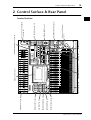 19
19
-
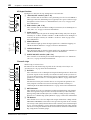 20
20
-
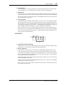 21
21
-
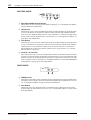 22
22
-
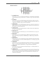 23
23
-
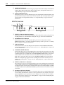 24
24
-
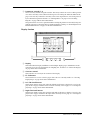 25
25
-
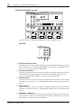 26
26
-
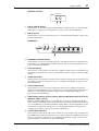 27
27
-
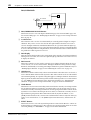 28
28
-
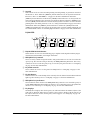 29
29
-
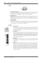 30
30
-
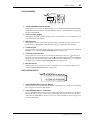 31
31
-
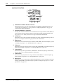 32
32
-
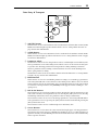 33
33
-
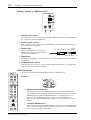 34
34
-
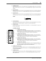 35
35
-
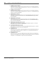 36
36
-
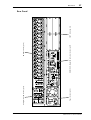 37
37
-
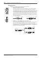 38
38
-
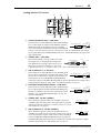 39
39
-
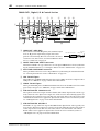 40
40
-
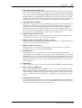 41
41
-
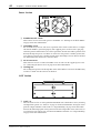 42
42
-
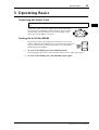 43
43
-
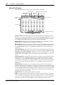 44
44
-
 45
45
-
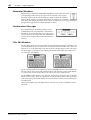 46
46
-
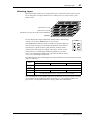 47
47
-
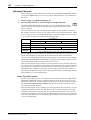 48
48
-
 49
49
-
 50
50
-
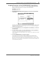 51
51
-
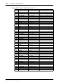 52
52
-
 53
53
-
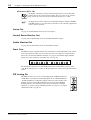 54
54
-
 55
55
-
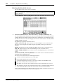 56
56
-
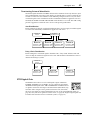 57
57
-
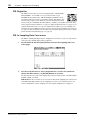 58
58
-
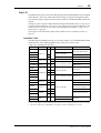 59
59
-
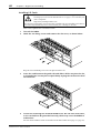 60
60
-
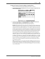 61
61
-
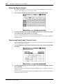 62
62
-
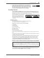 63
63
-
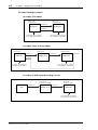 64
64
-
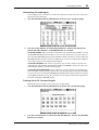 65
65
-
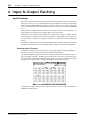 66
66
-
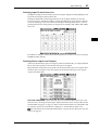 67
67
-
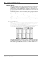 68
68
-
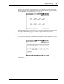 69
69
-
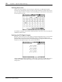 70
70
-
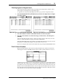 71
71
-
 72
72
-
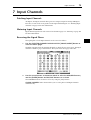 73
73
-
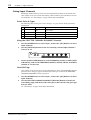 74
74
-
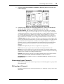 75
75
-
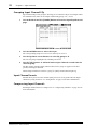 76
76
-
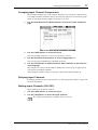 77
77
-
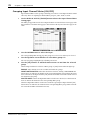 78
78
-
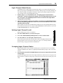 79
79
-
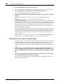 80
80
-
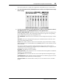 81
81
-
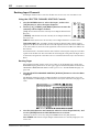 82
82
-
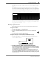 83
83
-
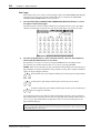 84
84
-
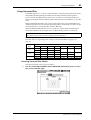 85
85
-
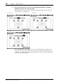 86
86
-
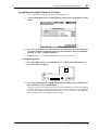 87
87
-
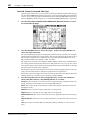 88
88
-
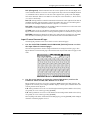 89
89
-
 90
90
-
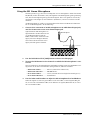 91
91
-
 92
92
-
 93
93
-
 94
94
-
 95
95
-
 96
96
-
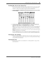 97
97
-
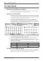 98
98
-
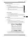 99
99
-
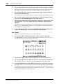 100
100
-
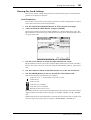 101
101
-
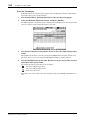 102
102
-
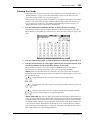 103
103
-
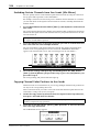 104
104
-
 105
105
-
 106
106
-
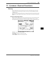 107
107
-
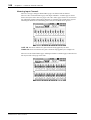 108
108
-
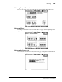 109
109
-
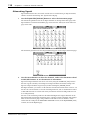 110
110
-
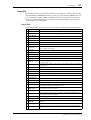 111
111
-
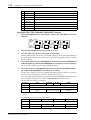 112
112
-
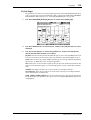 113
113
-
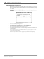 114
114
-
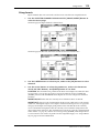 115
115
-
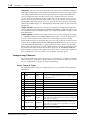 116
116
-
 117
117
-
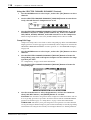 118
118
-
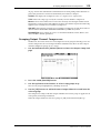 119
119
-
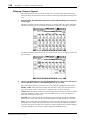 120
120
-
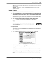 121
121
-
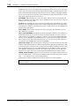 122
122
-
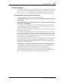 123
123
-
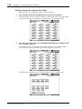 124
124
-
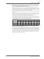 125
125
-
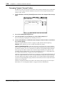 126
126
-
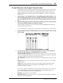 127
127
-
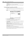 128
128
-
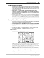 129
129
-
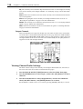 130
130
-
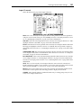 131
131
-
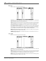 132
132
-
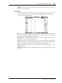 133
133
-
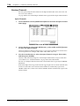 134
134
-
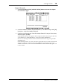 135
135
-
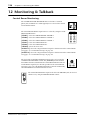 136
136
-
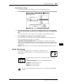 137
137
-
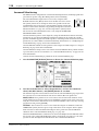 138
138
-
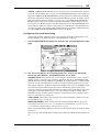 139
139
-
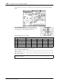 140
140
-
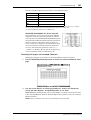 141
141
-
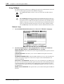 142
142
-
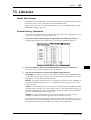 143
143
-
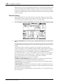 144
144
-
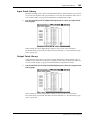 145
145
-
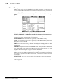 146
146
-
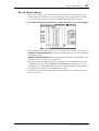 147
147
-
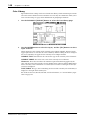 148
148
-
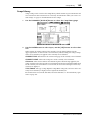 149
149
-
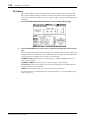 150
150
-
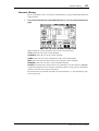 151
151
-
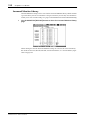 152
152
-
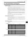 153
153
-
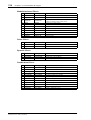 154
154
-
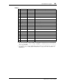 155
155
-
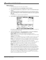 156
156
-
 157
157
-
 158
158
-
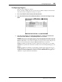 159
159
-
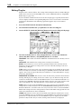 160
160
-
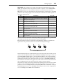 161
161
-
 162
162
-
 163
163
-
 164
164
-
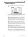 165
165
-
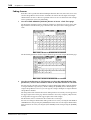 166
166
-
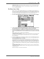 167
167
-
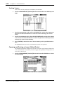 168
168
-
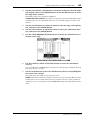 169
169
-
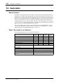 170
170
-
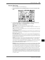 171
171
-
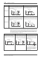 172
172
-
 173
173
-
 174
174
-
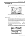 175
175
-
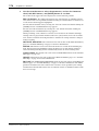 176
176
-
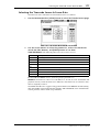 177
177
-
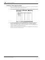 178
178
-
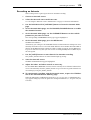 179
179
-
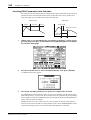 180
180
-
 181
181
-
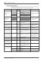 182
182
-
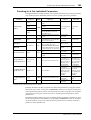 183
183
-
 184
184
-
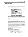 185
185
-
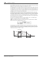 186
186
-
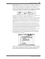 187
187
-
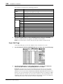 188
188
-
 189
189
-
 190
190
-
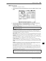 191
191
-
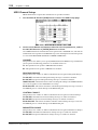 192
192
-
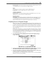 193
193
-
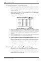 194
194
-
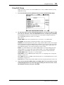 195
195
-
 196
196
-
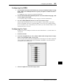 197
197
-
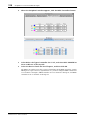 198
198
-
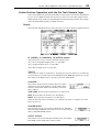 199
199
-
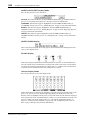 200
200
-
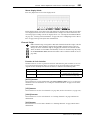 201
201
-
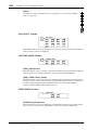 202
202
-
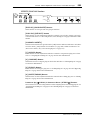 203
203
-
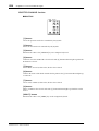 204
204
-
 205
205
-
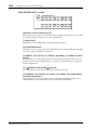 206
206
-
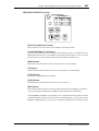 207
207
-
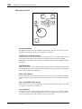 208
208
-
 209
209
-
 210
210
-
 211
211
-
 212
212
-
 213
213
-
 214
214
-
 215
215
-
 216
216
-
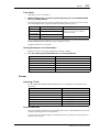 217
217
-
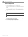 218
218
-
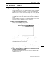 219
219
-
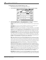 220
220
-
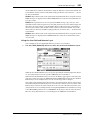 221
221
-
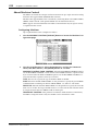 222
222
-
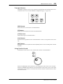 223
223
-
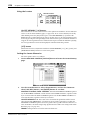 224
224
-
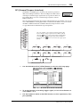 225
225
-
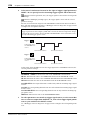 226
226
-
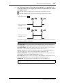 227
227
-
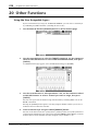 228
228
-
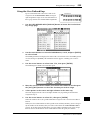 229
229
-
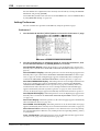 230
230
-
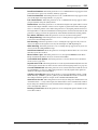 231
231
-
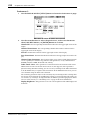 232
232
-
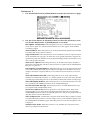 233
233
-
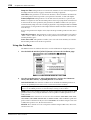 234
234
-
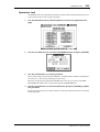 235
235
-
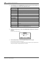 236
236
-
 237
237
-
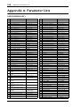 238
238
-
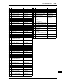 239
239
-
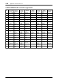 240
240
-
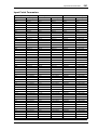 241
241
-
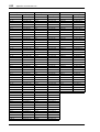 242
242
-
 243
243
-
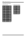 244
244
-
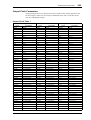 245
245
-
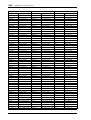 246
246
-
 247
247
-
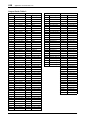 248
248
-
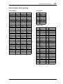 249
249
-
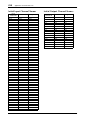 250
250
-
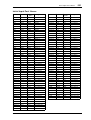 251
251
-
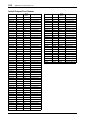 252
252
-
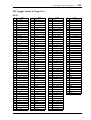 253
253
-
 254
254
-
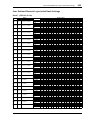 255
255
-
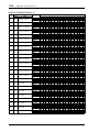 256
256
-
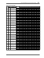 257
257
-
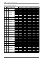 258
258
-
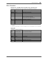 259
259
-
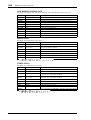 260
260
-
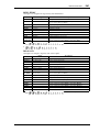 261
261
-
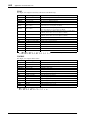 262
262
-
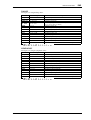 263
263
-
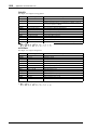 264
264
-
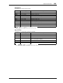 265
265
-
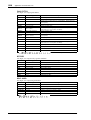 266
266
-
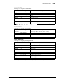 267
267
-
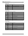 268
268
-
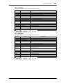 269
269
-
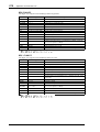 270
270
-
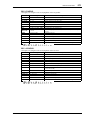 271
271
-
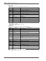 272
272
-
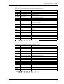 273
273
-
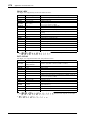 274
274
-
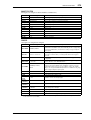 275
275
-
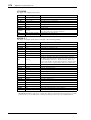 276
276
-
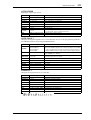 277
277
-
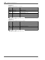 278
278
-
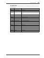 279
279
-
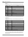 280
280
-
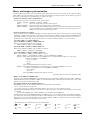 281
281
-
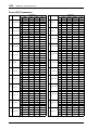 282
282
-
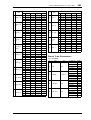 283
283
-
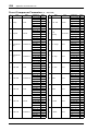 284
284
-
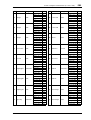 285
285
-
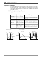 286
286
-
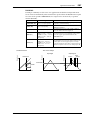 287
287
-
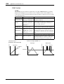 288
288
-
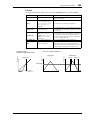 289
289
-
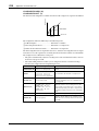 290
290
-
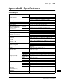 291
291
-
 292
292
-
 293
293
-
 294
294
-
 295
295
-
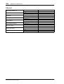 296
296
-
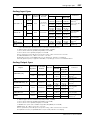 297
297
-
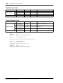 298
298
-
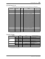 299
299
-
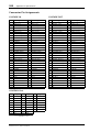 300
300
-
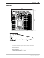 301
301
-
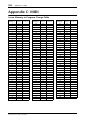 302
302
-
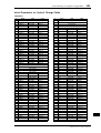 303
303
-
 304
304
-
 305
305
-
 306
306
-
 307
307
-
 308
308
-
 309
309
-
 310
310
-
 311
311
-
 312
312
-
 313
313
-
 314
314
-
 315
315
-
 316
316
-
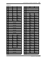 317
317
-
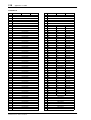 318
318
-
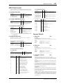 319
319
-
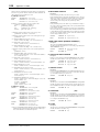 320
320
-
 321
321
-
 322
322
-
 323
323
-
 324
324
-
 325
325
-
 326
326
-
 327
327
-
 328
328
-
 329
329
-
 330
330
-
 331
331
-
 332
332
-
 333
333
-
 334
334
-
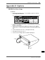 335
335
-
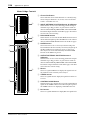 336
336
-
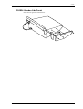 337
337
-
 338
338
-
 339
339
-
 340
340
-
 341
341
-
 342
342
-
 343
343
-
 344
344
-
 345
345
-
 346
346
-
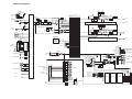 347
347
-
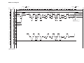 348
348
-
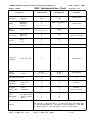 349
349
-
 350
350


Yamaha 02R96 Bedienungsanleitung
- Kategorie
- DJ-Controller
- Typ
- Bedienungsanleitung
in anderen Sprachen
- English: Yamaha 02R96 Owner's manual
- français: Yamaha 02R96 Le manuel du propriétaire
- español: Yamaha 02R96 El manual del propietario
- italiano: Yamaha 02R96 Manuale del proprietario
- русский: Yamaha 02R96 Инструкция по применению
- Nederlands: Yamaha 02R96 de handleiding
- português: Yamaha 02R96 Manual do proprietário
- dansk: Yamaha 02R96 Brugervejledning
- polski: Yamaha 02R96 Instrukcja obsługi
- čeština: Yamaha 02R96 Návod k obsluze
- svenska: Yamaha 02R96 Bruksanvisning
- Türkçe: Yamaha 02R96 El kitabı
- suomi: Yamaha 02R96 Omistajan opas
- română: Yamaha 02R96 Manualul proprietarului
Verwandte Artikel
-
Yamaha R96 Bedienungsanleitung
-
-
Yamaha DM2000 Bedienungsanleitung
-
Yamaha V96i Benutzerhandbuch
-
-
 Dan Dugan Sound Design MY16 Benutzerhandbuch
-
-
-
-
Yamaha MSR100 Benutzerhandbuch

Andere Dokumente
-
Ecler DP300 Benutzerhandbuch
-
LD AM8 Benutzerhandbuch
-
-
Sharp 8M-B120C Bedienungsanleitung
-
Peavey PC 1600X Bedienungsanleitung
-
Marantz PMD-706 Benutzerhandbuch
-
-
Musway TUNE12 12 Channel DSP Processor Benutzerhandbuch
-
Sigma R500T EOX Remote 500 Smart Control Center Benutzerhandbuch
-
Mpow T331 Headset Benutzerhandbuch