Falmec GRUPPO INCASSO 50CM Bedienungsanleitung
- Kategorie
- Dunstabzugshauben
- Typ
- Bedienungsanleitung
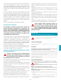
Dieses Handbuch eignet sich auch für

IT LIBRETTO ISTRUZIONI
EN INSTRUCTIONS BOOKLET
DE GEBRAUCHSANWEISUNG
FR MODE D'EMPLOI
ES MANUAL DE INSTRUCCIONES
RU ИНСТРУКЦИИ
PL INSTRUKCJA OBSŁUGI
NL HANDLEIDING
PT MANUAL DE INSTRUÇÕES
DK BRUGSANIVSNINGER
SE INSTRUKTIONSBOK
FI OHJEKIRJA
NO BRUKSANVISNING
gruppo incasso
gruppo incasso Green Tech
gruppo incasso Murano

2
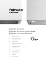
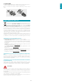
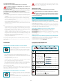
Gruppo incasso 100: 15 kg
Gruppo incasso 70: 12 kg
Gruppo incasso 50: 10 kg
Gruppo incasso Murano 70: 13 kg
Gruppo incasso Murano 50: 11 kg
262
1053 / 776 / 531
294
93
150
780 / 502 / 257
319
259
263
min 12/max 20
1017 / 739 / 494
108
1029 / 751 / 506
IT - MISURE FORO PER INCASSO
EN - HOLE MEASUREMENTS FOR INSTALLATION
DE - LOCHABMESSUNGEN FÜR EINBAU
FR - MESURES DU TROU POUR ENCASTREMENT
ES - MEDIDAS DEL ORIFICIO PARA EMPOTRADO
RU -
PL - WYMIARY OTWORU DO ZABUDOWY
NL - MATEN GAT VOOR INBOUW
PT - MEDIDAS DO FURO PARA EMBUTIR
DK - MÅL TIL ÅBNING FOR INDBYGNING
SE - MÅTT HÅL FÖR INBYGGNAD
FI - AUKON MITAT UPOTUSTA VARTEN
NO - HULLMÅL FOR INNFELLING
800
m
3
/h

ITALIANO
3
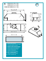
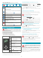
Gruppo incasso Green Tech 70: 13 kg
Gruppo incasso Green Tech 50: 11 kg
751 / 506
262
739 / 494
502 / 257
776 / 531
294
150
93
319
259
294
263
108
IT - MISURE FORO PER INCASSO
EN - HOLE MEASUREMENTS FOR INSTALLATION
DE - LOCHABMESSUNGEN FÜR EINBAU
FR - MESURES DU TROU POUR ENCASTREMENT
ES - MEDIDAS DEL ORIFICIO PARA EMPOTRADO
RU -
PL - WYMIARY OTWORU DO ZABUDOWY
NL - MATEN GAT VOOR INBOUW
PT - MEDIDAS DO FURO PARA EMBUTIR
DK - MÅL TIL ÅBNING FOR INDBYGNING
SE - MÅTT HÅL FÖR INBYGGNAD
FI - AUKON MITAT UPOTUSTA VARTEN
NO - HULLMÅL FOR INNFELLING
800
m
3
/h

4
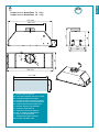
Gruppo incasso 70: 12 kg
Gruppo incasso 50: 10 kg
751 / 506
739 / 494
262
776 / 531
294
120
74
502 / 257
259
263
337
min 12/max 20
108
600
m
3
/h
IT - MISURE FORO PER INCASSO
EN - HOLE MEASUREMENTS FOR INSTALLATION
DE - LOCHABMESSUNGEN FÜR EINBAU
FR - MESURES DU TROU POUR ENCASTREMENT
ES - MEDIDAS DEL ORIFICIO PARA EMPOTRADO
RU -
PL - WYMIARY OTWORU DO ZABUDOWY
NL - MATEN GAT VOOR INBOUW
PT - MEDIDAS DO FURO PARA EMBUTIR
DK - MÅL TIL ÅBNING FOR INDBYGNING
SE - MÅTT HÅL FÖR INBYGGNAD
FI - AUKON MITAT UPOTUSTA VARTEN
NO - HULLMÅL FOR INNFELLING

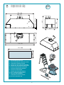
5
620
mm
MO
3
MO
Max 20 mm
Min 12 mm
2
1
2
3
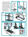
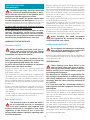
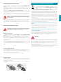
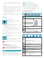
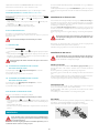
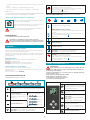
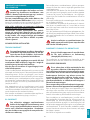
IT - Misure installazione (1), foratura pensile (2),
inserimento cappa (3), ssaggio al pensile (4)
EN - Installation measurements (1), wall unit hole (2),
hood installation (3), tting to the wall unit (4)
DE - Installationsabmessungen (1), Bohrung Hängekasten (2),
Einfügen der Abzugshaube (3), Befestigung am Hängekasten (4)
FR -
Mesures pour installation (1), perçage meuble (2),
mise en place de la hotte (3), xation au meuble (4)
ES -
Medidas instalación (1), oricio armario de pared (2),
introducción campana (3), jación en el armario de pared (4)
RU -
(1),
(2), (3), (4)
PL - Wymiary instalacji (1), nawiercenie szafki wiszącej (2),
wsunięcie okapu (3), mocowanie do szafki wiszącej (4)
NL - Installatiematen (1), opening keukenkastje (2),
plaatsing kap (3), bevestiging aan het keukenkastje (4)
PT -
Medidas para a instalação (1), perfuração de elemento suspen-
so (2), inserção da coifa (3) e xação ao elemento suspenso (4)
DK - Installationsmål (1), hul i skab (2),
Isætning af emhætten (3), fastgørelse til skab (4)
SE - Mått installation (1), hål skåp (2),
insättning av kåpa (3), fastsättning i skåpet (4)
FI - Asennusmitat (1), hyllyn aukon teko (2),
liesituulettimen paikalleen asetus (3), kiinnitys hyllyyn (4)
NO - Installasjonsmål (1), boring i veggskap (2),
innsetting av ventilatorhette (3), festing til veggskap (4)
V1 (x4)
Only for
maint.
1
V1 (x4)
V1 (x4)
OK!
2
3
NO!
4
1
MAGNET

6
M
ERM
ERM
1
4 5 6
2 3
ø 15
ø 12
600
m
3
/h
150mm
122mm
800
m
3
/h
5
6 7
800
m
3
/h
Only for
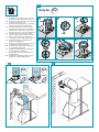
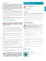
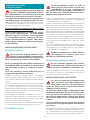
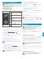
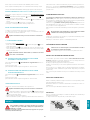
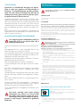
IT - Installazione valvola di non ritorno (5), tubo
di aspirazione (6) e collegamento elettrico (7)
EN - Installation of check valve (5), suction pipe (6)
and electrical connection (7)
DE - Installation des Rückschlagventils (5), des Absaug-
rohrs (6) und der elektrischen Verbindung (7)
FR - Installation clapet de non retour (5), tuyau
d'aspiration (6) et branchement électrique (7)
ES - Instalación de la válvula de no-retorno (5),
tubo de aspiración (6) y conexión eléctrica (7)
RU -
(5),
(6) (7)
PL - Instalacja zaworu zwrotnego (5), przewodu
zasysającego (6) i podłączenia elektrycznego (7)
NL - Installatie keerklep (5), afzuigbuis (6) en
elektrische aansluiting (7)
PT - Instalação da válvula de não retorno (5), tubo
de aspiração (6) e ligação elétrica (7)
DK - Installation af kontraventil (5), rør til udsug
(6) og elektrisk tilslutning (7)
SE - Installation av backventil (5), utsugningsrör
(6) samt elektrisk anslutning (7)
FI - Vastaventtiilin (5) asennus, imuputki (6) ja
sähköliitäntä (7)
NO - Installasjon av tilbakeslagsventil (5), innsu-
gingsrør (6) og elektrisk tilkobling (7)

7
3
1 2
600
m
3
/h
800
m
3
/h
9
10
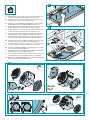
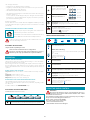
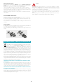
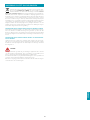
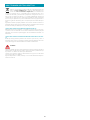
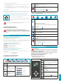
IT - Montaggio ltro carbone attivo di serie: rimuovere pannello (8), ri-
muovere ltri metallici (9), montare ltri carbone attivo (10).
EN - Assembling standard active carbon lter: remove panel (8), remove
metal lters (9), assemble active carbon lters (10).
DE - Montage des standardmäßigen Aktivkohlelters: Platte entfernen
(8), Metalllter entfernen (9), Aktivkohlelter montieren (10).
FR - Montage ltre au charbon actif standard : déposer le panneau (8), retirer
les ltres métalliques (9), monter les ltres au charbon actif (20).
ES - Montaje del ltro de carbón activo de serie: quite el panel (8), quite
los ltros metálicos (9), monte los ltros de carbón activo (10).
RU -
: (8), -
(9), (10).
PL - Montaż ltra z węglem aktywnym występującego w wyposażeniu seryjnym: zdjąć
panel (8), zdjąć metalowe ltry (9), zamontować ltry z węglem aktywnym (10).
NL - Montage serieel actief koolstolter: verwijder paneel (8), verwijder
de metalen lters (9), monteer de actieve koolstolters (10).
PT - Montagem do ltro de carvão ativado de série: remover o painel (8), remo-
ver os ltros metálicos (9) e montar os ltros de carvão ativado (10).
DK - Montage af medfølgende kullter: Fjern panelet (8), ern metall-
trene (9), monter de aktive kulltre (10).
SE - Montering av aktivt standardkollter: ta bort panelen (8), ta bort me-
tallfettltren (9), montera de aktiva kolltren (10).
FI - Sarjaan kuuluvan aktiivihiilisuodattimen asennus: poista levy (8), poista
metallisuodattimet (9), asenna aktiivihiilisuodattimet (10) paikalleen.
NO - Montering av standard aktivt kulllter: ern panelet (8), ern metall-
ltrene (9), monter de aktive kullltrene (10).
Green
Tech
8

8
5
1
2 3 4
3
1 2
1
2
V1 (x4)
2
1
11
12 14
13
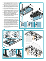
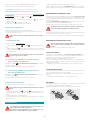
IT - Procedura di disinstallazione: rimuovere pannello (11),
rimuovere ltri metallici (12), svitare viti di tenuta(13),
sbloccare gruppo incasso (14).
EN - How to uninstall: remove panel (11), remove metal
lters (12), unscrew xing screws (13), release built-in
unit (14).
DE - Demontage-Methode: Platte entfernen (11), Metall-
lter entfernen (12), Dichtungsschrauben lösen (13),
Einbaugruppe freigeben(14).
FR - Procédure de désinstallation : déposer le panneau
(11), enlever les ltres métalliques (12), dévisser les vis
de xation (13), extraire le groupe à encastrement (14).
ES - Procedimiento de desmontaje: quite el panel (11), quite
los ltros metálicos (12), destornille los tornillos de
jación (13), desbloquee el grupo de empotrado (14).
RU - : (11),
(12),
(13), (14).
PL - Procedura dezinstalacji: zdjąć panel (11), zdjąć meta-
lowe ltry (12), odkręcić śruby przytrzymujące (13),
odblokować zespół do zabudowy (14).
NL - Demontageprocedure: verwijder het paneel (11), ver-
wijder de metalen lters (12), schroef de afdichtings-
schroeven (13) los, deblokkeer de inbouwgroep (14).
PT - Procedimento de desinstalação: remover o painel (11), re-
mover os ltros metálicos (12), desaparafusar os parafusos
de vedação(13) e desbloquear o grupo de embutir (14).
DK - Procedure for nedtagning: ern panelet (11), ern
metalltrene (12), skru skruerne, der holder emhætten
fast, løse (13), frigør enheden til indbygning (14).
SE - Procedur för avinstallation: ta bort panelen (11), ta
bort metallfettltren (12), skruva loss tätningsskru-
varna (13) och frigör den inbyggda enheten (14).
FI - Asennuksen purkaminen: poista levy (11), poista me-
tallisuodattimet (12), avaa kiinnitysruuvit (13), irrota
upotettu yksikkö (14).
NO - Prosedyre for avinstallering: ern panelet (11), ern
metallltrene (12), skru av holdeskruene (13), frigjør
innfellingsenheten (14).
IT - Staffa di sicurezza (Tirare!)
EN - Safety bracket (Pull!)
DE -
Sicherungsbügel (Daran ziehen!)
FR - Patte de sécurité (Tirer !)
ES
- Abrazadera de seguridad (¡Tire!)
RU -
Предохранительный кронштейн (Потянуть!)
PL - Obejma zabezpieczająca (Pociągnąć!)
NL - Veiligheidsbeugel (Trekken!)
PT -
Suporte de segurança (Puxar!)
DK - Sikkerhedsstænger (Træk!)
SE - Säkerhetsfäste (Dra!)
FI - Turvavipu (Vedä!)
NO - Sikkerhetsbrakett (Trekk!)

ITALIANO
9
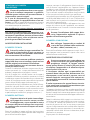
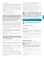
ISTRUZIONI DI SICUREZZA
E AVVERTENZE
Il lavoro d’installazione deve essere esegui-
to da installatori competenti e qualicati,
secondo quanto indicato nel presente libretto e
rispettando le norme in vigore.
Se il cavo di alimentazione o altri componenti
sono danneggiati, la cappa NON deve essere uti-
lizzata: staccare la cappa dall'alimentazione elettrica
e contattare il Rivenditore o un Centro Assistenza Tec-
nica autorizzato per la riparazione.
Non modicare la struttura elettrica, meccanica e
funzionale dell'apparecchiatura.
Non tentare di eettuare da soli riparazioni o so-
stituzioni: gli interventi eettuati da persone non
competenti e qualicate possono provocare dan-
ni, anche molto gravi, a cose e/o persone non co-
perti da garanzia del Costruttore.
AVVERTENZE PER L'INSTALLATORE
SICUREZZA TECNICA
Prima di installare la cappa controllare l'in-
tegrità e funzionalità di ogni sua parte: se
si notano anomalie non procedere nell'installa-
zione e contattare il Rivenditore.
Nel caso sia stato riscontrato un difetto estetico la
cappa NON deve essere installata; riporla nel suo
imballo originale e contattare il Rivenditore.
Una volta installata non sarà accettato alcun re-
clamo per difetti estetici.
Durante l'installazione utilizzare sempre mezzi di pro-
tezione personale (es.: scarpe antiinfortunistiche) ed
adottare comportamenti prudenti e corretti.
Il kit di fissaggio (viti e tasselli) fornito con la cappa è
utilizzabile unicamente su pareti in muratura: in caso di
installazione su pareti di materiale diverso, valutare altri
sistemi di fissaggio tenendo conto della resistenza del
muro e del peso della cappa (indicato a pag. 2).
Tenere presente che l’installazione con sistemi di fissag-
gio diversi da quelli forniti o non conformi può com-
portare rischi di natura elettrica e di tenuta meccanica.
Non installare la cappa in ambienti esterni e non
esporla ad agenti atmosferici (pioggia, vento, ecc...).
SICUREZZA ELETTRICA
L’impianto elettrico al quale viene collega-
ta la cappa deve essere a norma e munito
di collegamento a terra secondo le norme
di sicurezza del Paese di utilizzo; deve essere inol-
tre conforme alle normative Europee sull’antidi-
sturbo radio.
Prima di installare la cappa verificare che la tensione
di rete corrisponda a quella riportata dalla targhetta
posta all’interno della cappa.
La presa usata per il collegamento elettrico deve es-
sere facilmente raggiungibile con l’apparecchiatura
installata: in caso contrario, prevedere un interruttore
generale per disconnettere la cappa al bisogno.
Ogni eventuale modifica all’impianto elettrico dovrà
essere eseguita solo da un elettricista qualificato.
La lunghezza massima della vite di fissaggio del cami-
no (fornita dal fabbricante) è di 13 mm. L'utilizzo di viti
non conformi con le presenti istruzioni può compor-
tare rischi di natura elettrica.
In caso di malfunzionamenti dell’apparecchio, non
tentare di risolvere da soli il problema, ma contatta-
re il Rivenditore o un Centro di Assistenza autorizzato
per la riparazione.
Durante l'installazione della cappa, disin-
serire l’apparecchio togliendo la spina o
agendo sull’interruttore generale.
SICUREZZA SCARICO FUMI
Non collegare l’apparecchio a condotti di
scarico dei fumi prodotti dalla combustio-
ne (ad es. caldaie, caminetti, ecc...)
Prima dell'installazione della cappa assicurarsi che si-
ano rispettate tutte le normative vigenti sullo scarico
dell’aria all’esterno del locale.
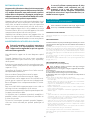
AVVERTENZE PER L'UTILIZZATORE
Queste avvertenze sono state redatte per
la vostra sicurezza e per quella degli altri, Vi
preghiamo, dunque, di leggere attenta-
mente questo libretto in tutte le sue parti prima
di utilizzare l’apparecchio o di eettuare opera-
zioni di pulizia sullo stesso.
Il Costruttore declina ogni responsabilità per
eventuali danni che possano, direttamente o in-
direttamente, essere causati a persone, cose ed
animali domestici conseguenti alla mancata os-
servanza delle avvertenze di sicurezza indicate in
questo libretto.
È molto importante che questo libretto istruzio-
ni sia conservato insieme all’apparecchiatura per
qualsiasi futura consultazione.
Se l’apparecchio dovesse essere venduto o trasferito ad
un’altra persona, assicurarsi che anche il libretto venga
fornito, in modo che il nuovo utente possa essere messo
al corrente del funzionamento della cappa e delle avver-
tenze relative.
Dopo l’installazione delle cappe in acciaio inox è ne-
cessario eseguire la pulizia della stessa per rimuove-
re i residui di collante del protettivo e le eventuali
macchie di grasso e oli, che, se non rimosse, possono
causare il deterioramento irreversibile della superficie
della cappa. Per questa operazione il costruttore rac-
comanda l’utilizzo delle salviette in dotazione, dispo-
nibili anche in acquisto.
Esigere parti di ricambio originali.

10
DESTINAZIONE D'USO
L’apparecchio è destinato solo ed esclusivamente per
l'aspirazione di fumi generati dalla cottura di alimen-
ti in ambito domestico, non professionale: qualsiasi
utilizzo diverso da questo è improprio, può provoca-
re danni a persone, cose ed animali domestici e solle-
va il Costruttore da qualsiasi responsabilità.
L’apparecchio può essere utilizzato da bambini di età
non inferiore a 8 anni e da persone con ridotte capa-
cità fisiche, sensoriali o mentali, o prive di esperienza
o della necessaria conoscenza, purché sotto sorve-
glianza oppure dopo che le stesse abbiano ricevuto
istruzioni relative all’uso sicuro dell’apparecchio e alla
comprensione dei pericoli ad esso inerenti.
I bambini non devono giocare con l’apparecchio. La
pulizia e la manutenzione a cura dell’utilizzatore non
deve essere effettuata da bambini senza sorveglianza.
AVVERTENZE PER L'UTILIZZO E LA PULIZIA
Prima di procedere a qualsiasi operazione
di pulizia o di manutenzione, disinserire
l’apparecchio togliendo la spina o agendo
sull’interruttore generale.
Non utilizzare la cappa con le mani bagnate o piedi
scalzi.
Quando l’apparecchio non viene usato, controllare
sempre che tutte le parti elettriche, (luci, aspiratore),
siano spente.
Il peso massimo complessivo di eventuali oggetti po-
sizionati o appesi (ove previsto) sulla cappa non deve
superare 1,5 Kg.
Controllare le friggitrici durante l’uso: I’olio surriscal-
dato potrebbe infiammarsi.
Non accendere fiamme libere sotto la cappa.
Non preparare cibi alla fiamma sotto la cappa.
Non utilizzare mai la cappa senza i filtri metallici anti-
grasso; grasso e sporco in questo caso si depositereb-
bero nell'apparecchio compromettendone il funzio-
namento.
Parti accessibili della cappa possono essere calde se
utilizzate insieme con apparecchi di cottura.
Non effettuare operazioni di pulizia quando parti del-
la cappa sono ancora calde.
Se la pulizia non è condotta secondo le modalità e i
prodotti indicati nel presente libretto è possibile un
rischio di incendio.
Disinserire l’interruttore generale quando l’apparec-
chio non viene utilizzato per periodi prolungati di
tempo.
In caso di utilizzo contemporaneo di altre
utenze (caldaie, stufe, caminetti, ecc.) ali-
mentate a gas o con altri combustibili,
provvedere ad una adeguata ventilazione
del locale in cui avviene l’aspirazione dei fumi, se-
condo le norme vigenti.
INSTALLAZIONE
parte riservata solo a personale qualicato
Prima di eettuare l'installazione della cappa, leggere attenta-
mente il cap. "ISTRUZIONI DI SICUREZZA E AVVERTENZE".
CARATTERISTICHE TECNICHE
I dati tecnici dell'apparecchio sono riportati su etichette posizionate all’interno
della cappa.
POSIZIONAMENTO
La distanza minima fra la parte più alta dell'apparecchiatura per la cottura
e la parte più bassa della cappa da cucina viene indicata nelle istruzioni di
montaggio.
In generale, quando la cappa da cucina è posta su un piano cottura a gas, questa
distanza deve essere almeno 65 cm (25,6"). Tuttavia sulla base di un’interpreta-
zione della norma EN60335-2-31 del 11-07-2002 da parte del TC61 (subclause
7.12.1 meeting 15 agenda item 10.11), la distanza minima tra piano cottura e
parte inferiore della cappa può essere ridotta alla quota riportata nelle istruzioni
di montaggio.
Se le istruzioni del piano di cottura a gas specificano una distanza maggiore,
bisogna tenerne conto.
Non installare la cappa in ambienti esterni e non esporla ad agenti atmosferici
(pioggia, vento, ecc...).
COLLEGAMENTO ELETTRICO
(parte riservata solo a personale qualicato)
Prima di eettuare qualsiasi operazione sulla cappa scollegare
l’apparecchio dalla rete elettrica.
Assicurarsi che non vengano scollegati o tagliati li elettrici all’in-
terno della cappa:
in caso contrario contattare il Centro Assistenza più vicino.
Per l’allacciamento elettrico rivolgersi a personale qualicato.
Il collegamento deve essere eseguito in conformità con le disposizioni di
legge in vigore.
Prima di collegare la cappa alla rete elettrica, controllare che:
• la tensione di rete corrisponda a quella riportata sui dati di targa posti all’in-
terno della cappa;
• l’impianto elettrico sia a norma e possa sopportare il carico (vedi caratteristi-
che tecniche posizionate all’interno della cappa);
• la spina e il cavo, di alimentazione, non devono entrare in contatto con tem-
perature superiori a 70 °C;
• l’impianto di alimentazione sia munito di efficace e corretto collegamento di
terra secondo le norme vigenti;
• la presa usata per il collegamento sia facilmente raggiungibile una volta in-
stallata la cappa.
In caso di :
• apparecchi dotati di cavo senza spina: la spina da utilizzare deve essere di tipo
“normalizzato”. Il fili devono essere collegati come segue: giallo-verde per
la messa a terra, blu per il neutro e il filo marrone per la fase. La spina deve
essere collegata ad un'adeguata presa di sicurezza.
• apparecchio fisso non provvisto di cavo di alimentazione e di spina, o di altro
dispositivo che assicuri la disconnessione dalla rete, con una distanza di aper-
tura dei contatti che consenta la disconnessione completa nelle condizioni
della categoria di sovratensione III.
Tali dispositivi di disconnessione devono essere previsti nella rete di alimen-
tazione conformemente alle regole di installazione.
Il cavo di terra giallo/verde non deve essere interrotto dall’interruttore.
Il Costruttore declina ogni responsabilità nel caso le norme di sicurezza non ven-
gano rispettate.

ITALIANO
11
SCARICO FUMI
CAPPA AD EVACUAZIONE ESTERNA ASPIRANTE
In questa versione, fumi e vapori vengono convogliati verso
l'esterno attraverso il tubo di scarico.
A tal fine, il raccordo d'uscita della cappa, deve essere collega-
to tramite un tubo, ad un'uscita esterna.
Il tubo d'uscita deve avere:
• un diametro non inferiore a quello di raccordo della cappa.
• una leggera inclinazione verso il basso (caduta) nei tratti orizzontali per evitare
che la condensa refluisca nel motore.
• il numero minimo indispensabile di curve.
• la lunghezza minima indispensabile per evitare vibrazioni e di ridurre la capa-
cità aspirante della cappa.
E' necessario isolare la tubazione se passa attraverso ambienti freddi.
Per impedire ritorni d'aria dall'esterno, una valvola di non ritorno è presente in
presenza di motori con 800m3/h o superiori.
Deviazione per la Germania:
quando la cappa da cucina e apparecchi alimentati con energia diversa da quel-
la elettrica sono in funzione simultaneamente, la pressione negativa nel locale non
deve superare i 4 Pa (4 x 10⁻⁵ bar).
CAPPA A RICICLO INTERNO FILTRANTE
In questa versione l’aria passa attraverso i filtri al carbone attivo
per essere purificata e riciclata nell’ambiente.
Controllare che i filtri al carbone attivo siano montati sulla cap-
pa, in caso negativo applicarli come indicato nelle istruzioni
di montaggio.
In questa versione valvola di non ritorno non deve essere montata: ri-
muoverla se presente sul raccordo di uscita aria del motore.
ISTRUZIONI DI MONTAGGIO
parte riservata solo a personale qualicato
La cappa ha la possibilità di essere installata in varie congurazio-
ni. Le fasi di montaggio generiche valgono per tutte le installazio-
ni; seguire invece dove specicato le fasi corrispondenti all’instal-
lazione desiderata.
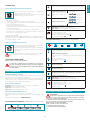
FUNZIONAMENTO
QUANDO ACCENDERE LA CAPPA?
Accendere la cappa almeno un minuto prima di iniziare a cucinare per convo-
gliare fumi e vapori verso la superficie di aspirazione.
Al termine della cottura lasciare in funzione la cappa fino a completa aspirazione
di tutti i vapori e odori: con la funzione Timer, è possibile impostare l'autospegni-
mento della cappa dopo 15 minuti di funzionamento.
QUALE VELOCITÀ SCEGLIERE?
I velocità: mantiene l’aria pulita con bassi consumi di energia elettrica.
II velocità: condizioni normali di utilizzo.
III velocità: presenza di forti odori e vapori.
IV velocità: rapidi smaltimenti di odori e vapori.
QUANDO LAVARE O CAMBIARE I FILTRI?
I filtri metallici devono essere lavati ogni 30 ore di utilizzo.
I filtri carbone attivo, vanno sostituiti ogni 3-4 mesi a seconda dell’utilizzo della
cappa.
Per ulteriori dettagli vedere cap “MANUTENZIONE”.
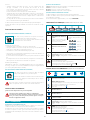
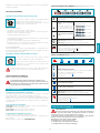
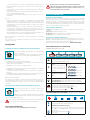
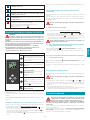
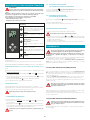
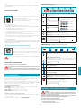
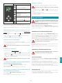
PULSANTIERA ELETTRONICA (GRUPPO INCASSO, Green Tech)
Motore ON/OFF
All’avvio, la velocità è quella memorizzata al precedente spegnimen-
to.
Incremento velocità da 1 a 4
Velocità 4 è attiva solo per al-
cuni minuti, poi si attiva velo-
cità 3.
Le velocità sono segnalate dai led
presenti nei tasti:
Velocità 1
Velocità 2
Velocità 3
Velocità 4
(led "+" lampeggiante)
Riduzione velocità da 4 a 1
Accensione / spegnimento luce
Impulso breve: accensione e spegnimento luce
Impulso lungo: cambio tonalità di luce da 2700K-5600K
TIMER (Led rosso lampeggiante)
Autospegnimento dopo 15min.
La funzione si disattiva (Led rosso spento) se:
- Si preme un'altra volta il tasto TIMER ( ).
- Si preme il tasto ON/OFF ( ).
PULSANTIERA TOUCH (GRUPPO INCASSO MURANO)
ON/OFF (led blu sso)
Accensione/spegnimento motore e Vel1
ON/OFF (led blu lampeggiante)
Premuto per più di 3 secondi attiva il ciclo 24h (1h ON -> 3h OFF ->
1h ON)
La funzione si disattiva se:
- si spegne il motore (tasto )
- Dopo 24h
Attivazione Velocità 2
Attivazione Velocità 3
Attivazione Velocità 4 solo per alcuni minuti, poi velocità 3
Accensione / spegnimento luce
Impulso breve: accensione e spegnimento luce
Impulso lungo: cambio tonalità di luce da 2700K-5600K
TIMER (Led rosso lampeggiante)
Autospegnimento dopo 15min.
La funzione si disattiva (Led rosso spento) se:
- Si spegne il motore (tasto ).
- Si varia la velocità.
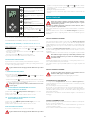
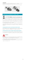
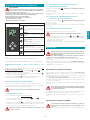
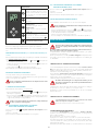
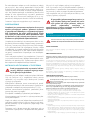
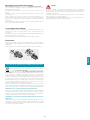
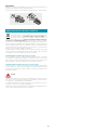
UTILIZZO DEL RADIOCOMANDO
AVVERTENZE!:
Posizionare la cappa lontano da sorgenti di onde elettromagneti-
che (es. forni a microonde) che potrebbero interferire con il radio-
comando e con l’elettronica della cappa.
La distanza massima di funzionamento è di 5 metri che può variare in di-
fetto in presenza di interferenze elettromagnetiche.
Radiocomando operante a 433,92MHz.
Il radiocomando è composto da due parti:
- la ricevente integrata nella cappa;
- la trasmittente mostrata qui in gura.

12
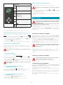
DESCRIZIONE COMANDI TRASMITTENTE
UP
Accensione motore e incremento velo-
cità da 1 a 4. La quarta velocità è attiva
solo per alcuni minuti.
DOWN
Decremento velocità e spegnimento
motore
Luce ON-OFF
Impulso breve:
accensione e spegnimento luce
Impulso lungo:
cambio tonalità di luce da 2700K-5600K
TIMER ON: Autospegnimento del mo-
tore dopo 15min.
La funzione si disattiva automaticamen-
te se si spegne il motore (tasto )
Trasmissione comando attiva
Il radiocomando è opzionale per il GRUPPO INCASSO e Green Tech.
In caso di acquisto, seguire per intero la procedura descritta qui sotto.
Per IL GRUPPO INCASSO MURANO, saltare la procedura di attivazione.
PROCEDURA DI ATTIVAZIONE (per GRUPPO INCASSO e Green Tech)
Prima di utilizzare il radiocomando, eseguire la seguente procedura sulla pul-
santiera della cappa:
• Premere contemporaneamente i tasti LUCE (
) e TIMER ( ) fino a che tutti
i led iniziano a lampeggiare.
• Rilasciare i due tasti e premere ancora il tasto LUCE ( ) fino a quando tutti i
led saranno accesi.
• Rilasciare il tasto LUCE ( ): adesso la ricevente è attiva.
La procedura serve anche per la disattivazione della ricevente.
CAMBIO CODICE RADIOCOMANDO
In presenza di un solo radiocomando passare direttamente al punto 2.
In presenza di più radiocomandi nella stessa stanza, è possibile generare un nuo-
vo codice con la seguente procedura.
Togliere alimentazione alla cappa prima di eettuare la procedura.
1 GENERARE UN NUOVO CODICE
La procedura va eseguita sul radiocomando.
• Premere contemporaneamente i tasti LUCE e TIMER fino a che il di-
splay incomincia a lampeggiare.
• Premere il tasto DOWN del radiocomando: la memorizzazione del nuovo
codice è confermata da 3 brevi lampeggi del display. Il nuovo codice annulla
e sostituisce il precedente codice di fabbrica.
Ricollegare la cappa alla rete elettrica, vericando che luci e moto-
re siano spenti.
2A ASSOCIAZIONE DEL RADIOCOMANDO ALLA CAPPA
CON PULSANTIERA ELETTRONICA
premere il tasto TIMER ( ) della pulsantiera della cappa per 2 secondi:
il led rosso si accende.
premere un tasto qualsiasi del radiocomando entro 10 secondi.
2B ASSOCIAZIONE DEL RADIOCOMANDO ALLA CAPPA
CON PULSANTIERA TOUCH
premere il tasto LUCE ( ) della pulsantiera della cappa per 2 secondi:
il led rosso si accende.
premere un tasto qualsiasi del radiocomando entro 10 secondi.
RIPRISTINO CODICE DI FABBRICA
la procedura è da effettuarsi in caso di cessione della cappa.
Togliere alimentazione alla cappa prima di eettuare la procedura.
• Premere contemporaneamente i tasti UP e DOWN del radiocomando
per più di 5 secondi: l'avvenuto ripristino viene confermato da tre brevi lam-
peggi del display.
• Ricollegare la cappa alla rete elettrica.
• Procedere con l’associazione tra cappa e radiocomando come descritto nel
punto 2.
MANUTENZIONE
Prima di procedere a qualsiasi operazione di pulizia o di manu-
tenzione, disinserire l’apparecchio togliendo la spina o agendo
sull’interruttore generale.
Non si devono utilizzare detergenti contenenti sostanze abrasive, acide o
corrosive e panni con superci ruvide.
Una costante manutenzione garantisce un buon funzionamento e rendimento
nel tempo.
Particolari attenzioni vanno rivolte ai filtri metallici antigrasso: la pulizia fre-
quente dei filtri e dei loro supporti garantisce che non si accumulino grassi in-
fiammabili.
PULIZIA SUPERFICI ESTERNE
Si raccomanda di pulire le superfici esterne della cappa almeno ogni 15 giorni
per evitare che le sostanze oleose o grasse possano intaccarle. Per la pulizia della
cappa, realizzata in acciaio inox spazzolato, il Costruttore consiglia l'utilizzo delle
salviette "Magic Steel" che si possono anche ordinare on-line sul sito www.e-fal-
mec.com.
In alternativa e per tutti gli altri tipi di superci, la pulizia va eseguita usando
un panno umido leggermente imbevuto di detersivo neutro liquido o con alcool
denaturato.
Terminare la pulizia con un accurato risciacquo e asciugatura con panni morbidi.
Non utilizzare troppa acqua in prossimità della pulsantiera e dei
dispositivi di illuminazione per evitare che l'umidità raggiunga
parti elettroniche.
La pulizia dei pannelli in vetro va eseguita solo con detergenti specifici non cor-
rosivi o abrasivi utilizzando un panno morbido.
Il Costruttore declina ogni responsabilità qualora non vengano rispettate tali
istruzioni.
PULIZIA SUPERFICI INTERNE
E’ vietata la pulizia di parti elettriche o parti relative al motore
all’interno della cappa, con liquidi o solventi.
Per le parti metalliche interne vedi paragrafo precedente.
FILTRI METALLICI ANTIGRASSO
Si consiglia di lavare frequentemente i filtri metallici (almeno ogni mese) la-
sciandoli in ammollo per circa 1 ora in acqua bollente con detersivo per piatti,
evitando di piegarli.
Non usare detergenti corrosivi, acidi o alcalini.
Risciacquarli con cura ed attendere che siano ben asciutti prima di rimontarli.
Il lavaggio in lavastoviglie è permesso, ma potrebbe creare imbrunimenti al
materiale dei filtri: per ridurre questo inconveniente utilizzare lavaggi a basse
temperature (55°C max.).
Per l’estrazione e l'inserimento dei filtri metallici antigrasso vedi istruzioni di
montaggio.
FILTRI AL CARBONE ATTIVO
Questi filtri trattengono gli odori presenti nell’aria che li attraversa. L’aria depura-
ta viene così rimessa nell’ambiente.
I filtri al carbone attivo devono essere sostituiti mediamente ogni 3-4 mesi in
condizioni di utilizzo normale.
Per la sostituzione dei filtri al carbone attivo vedi istruzioni di montaggio.

ITALIANO
13
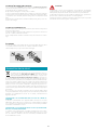
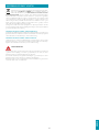
ILLUMINAZIONE
La cappa è dotata di illuminazione tramite faretti led ad alta efficienza, basso
consumo e durata molto elevata in condizioni di normale utilizzo.
Nel caso si rendesse necessaria la sostituzione del faretto procedere come in
figura.
12V
3
1
2
SMALTIMENTO A FINE VITA
Il simbolo del cestino barrato riportato sull’apparecchiatura in suo pos-
sesso indica che il prodotto è un RAEE, cioè un “Rifiuto derivante dal-
le Apparecchiature Elettriche ed Elettroniche” e pertanto non deve
essere gettato nella spazzatura indierenziata
(cioè insieme ai “rifiuti urbani
misti”), ma deve essere gestito separatamente così da essere sottoposto ad ap-
posite operazioni per il suo riutilizzo, oppure a uno specifico trattamento, per ri-
muovere e smaltire in modo sicuro le eventuali sostanze dannose per l’ambiente
ed estrarre le materie prime che possono essere riciclate. Lo smaltimento corret-
to di questo prodotto contribuirà a salvare preziose risorse ed evitare potenziali
effetti negativi per la salute umana e per l’ambiente, che potrebbero essere cau-
sati da uno smaltimento inappropriato dei rifiuti.
Vi preghiamo di contattare le autorità locali per ulteriori dettagli sul punto di
smaltimento designato più vicino. Potrebbero venire applicate delle penali per
lo smaltimento scorretto di questi rifiuti in conformità alla legislazione nazionale.
INFORMAZIONI SULLO SMALTIMENTO IN ITALIA
In Italia le apparecchiature RAEE devono perciò essere consegnate:
- ai Centri di Raccolta (chiamati anche isole ecologiche o piattaforme ecologi-
che) allestiti dai Comuni o dalle Società di igiene urbana (in molte località vie-
ne anche effettuato il servizio di ritiro a domicilio delle apparecchiature RAEE
ingombranti);
- al negozio presso il quale si acquista una nuova apparecchiatura, che è tenuto
a ritirarle gratuitamente (ritiro “uno contro uno”);
- ad un negozio qualunque*, che è tenuto a ritirarle gratuitamente e senza
obbligo di acquisto (ritiro “uno contro zero”).
In questo caso:
1) l’apparecchiatura RAEE, per poter essere riconsegnata, deve avere “piccolis-
sime dimensioni” (altezza, profondità e larghezza minori di 25 cm);
* 2) il negozio al quale viene riconsegnata l’apparecchiatura RAEE deve avere
una superficie di vendita superiore a 400 mq.
INFORMAZIONI SULLO SMALTIMENTO IN NAZIONI DELL'UNIONE EURO
PEA
La Direttiva comunitaria sulle apparecchiature RAEE è stata recepita in modo
diverso da ciascuna nazione, pertanto se si desidera smaltire questa apparec-
chiatura suggeriamo di contattare le autorità locali o il Rivenditore per chiedere
il metodo corretto di smaltimento.
INFORMAZIONI SULLO SMALTIMENTO IN NAZIONI NON APPARTENENTI
ALL'UNIONE EUROPEA
Il simbolo del cestino barrato è valido solamente nell’Unione Europea: se si de-
sidera smaltire questa apparecchiatura in altri Paesi suggeriamo di contattare le
autorità locali o il Rivenditore per chiedere il metodo corretto di smaltimento.
ATTENZIONE!
Il Costruttore si riserva il diritto di apportare modifiche alle apparecchiature in
qualsiasi momento e senza preavviso. La stampa, la traduzione e la riproduzione
anche parziale del presente manuale s’intendono vincolate dall’autorizzazione
del Costruttore.
Le informazioni tecniche, le rappresentazioni grafiche e le specifiche presenti in
questo manuale sono indicative e non divulgabili.
La lingua di stesura del manuale è l’italiano, il Costruttore non si rende responsa-
bile per eventuali errori di trascrizione o traduzione.

14
SAFETY INSTRUCTIONS
AND WARNINGS
Installation operations are to be carried out
by skilled and qualied installers in accor-
dance with the instructions in this booklet and in
compliance with the regulations in force.
DO NOT use the hood if the power supply cable
or other components are damaged:
disconnect the
hood from the electrical power supply and contact the
Dealer or an authorised Servicing Dealer for repairs.
Do not modify the electrical, mechanical or func-
tional structure of the equipment.
Do not personally try to carry out repairs or repla-
cements. Interventions carried out by incompe-
tent and unauthorised persons can cause serious
damage to the unit or physical and personal harm,
not covered by the Manufacturer's warranty.
WARNINGS FOR THE INSTALLER
TECHNICAL SAFETY
Before installing the hood, check the in-
tegrity and function of each part. Should
anomalies be noted, do not proceed with
installation and contact the Dealer.
Do NOT install the hood if an aesthetic (or cos-
metic) defect has been detected. Put it back into
its original package and contact the dealer.
No claim can be made for aesthetic (or cosmetic)
defects once it has been installed.
During installation, always use personal protective
equipment (e.g.: Safety shoes) and adopt prudent
and proper conduct.
The installation kit (screws and plugs) supplied with
the hood is only to be used on masonry walls: in case
of installation on walls of a different material, assess
other installation options keeping in mind the type
of wall surface and the weight of the hood (indicated
on page 2).
Keep in mind that installations with different types of
fastening systems from those supplied, or which are
not compliant, can cause electrical and mechanical
seal danger.
Do not install the hood outdoors and do not expose
it to atmospheric elements (rain, wind, etc.).
ELECTRICAL SAFETY
The electrical system to which the hood is
to be connected must be in accordance
with local standards and supplied with
earthed connection in compliance with safety
regulations in the country of use. It must also
comply with European standards regarding radio
antistatic properties.
Before installing the hood, check that the electrical
mains power supply corresponds with what is report-
ed on the identification plate located inside the hood.
The socket used to connect the installed equipment
to the electrical power supply must be within reach:
otherwise, install a mains switch to disconnect the
hood when required.
Any changes to the electrical system must be carried
out by a qualified electrician.
The maximum length of the flue fastening screws
(supplied by the manufacturer) must be 13 mm. Use
of non-compliant screws with these instructions can
lead to danger of an electrical nature.
Do not try to solve the problem yourself in the event
of equipment malfunction, but contact the Dealer or
an authorised Servicing Department for repairs.
When installing the hood, disconnect
the equipment by removing the plug or
switching o the main switch.
FUMES DISCHARGE SAFETY
Do no connect the equipment to discharge
pipes of fumes produced from combustion
(for example boilers, replaces, etc.).
Before installing the hood, ensure that all standards in
force regarding discharge of air out of the room have
been complied with.
USER WARNINGS
These warnings have been drawn up for
your personal safety and those of others.
You are therefore kindly asked to read the
booklet carefully in its entirety before using the
or cleaning the equipment.
The Manufacturer declines all responsibility for
any damage caused directly, or indirectly, to per-
sons, things and pets as a consequence of failing
to comply with the safety warnings indicated in
this booklet.
It is imperative that this instructions booklet is
kept together with the equipment for any future
consultation.
If the equipment is sold or transferred to another person,
make sure that the booklet is also supplied so that the
new user can be made aware of the hood's operation
and relative warnings.
After the stainless steel hood has been installed, it will
need to be cleaned to remove any residues remaining
from the protection adhesive as well as any grease and
oil stains which, if not removed, can cause irreversible
damage to the hood surface. To properly clean the unit,
the manufacturer recommends using the supplied
moist wipes, which are also available sold separately.
Insist on original spare parts.

15
ENGLISH
INTENDED USE
The equipment is solely intended to be used to
extract fumes generated from cooking food in
non-professional domestic kitchens: any other
use is improper. Improper use can cause damage
to persons, things, pets and exempts the Manu-
facturer from any liability.
The equipment can be used by children over the age
of 8 and by persons with reduced physical, sensory
and mental abilities, or with no experience or knowl-
edge, as long as they do so under supervision or after
having received relative instructions regarding safe
use of the equipment and understanding of the dan-
gers connected to it.
Children are not to play with the equipment. Clean-
ing and maintenance by the user must not be carried
out by children without supervision.
USE AND CLEANING WARNINGS
Before cleaning or carrying out mainte-
nance operations, disconnect the equip-
ment by removing the plug or switching
o the main switch.
Do not use the hood with wet hands or bare feet.
Always check that all electrical parts (lights, extractor
fan) are off when the equipment is not being used.
The maximum overall weight of any objects placed
or hung (if applicable) on the hood must not exceed
1.5 Kg.
Always supervise the cooking process during the use
of deep-fryers: Overheated oil can catch fire.
Do not leave open, unattended flames under the
hood.
Do not prepare food over an open flame under the
hood.
Never use the hood without the metal anti-grease
filters: in this case, grease and dirt will deposit in the
equipment and compromise its operation.
Accessible parts of the hood can be hot when used at
the same time as the cooking appliances.
Do not carry out any cleaning operations when parts
of the hood are still hot.
There can be a risk of fire if cleaning is not carried out
according to the instructions and products indicated
in this booklet.
Disconnect the main switch when the equipment is
not used for long periods of time.
If other appliances that use gas or other fu-
els are being used at the same time (boiler,
stove, replaces, etc.), make sure the room
where the fumes are discharged is well-ventilat-
ed, in compliance with the local regulations.
INSTALLATION
only intended for qualied personnel
Before installing the hood, carefully read the chapter 'SAFETY
INSTRUCTIONS AND WARNINGS'.
TECHNICAL FEATURES
The technical specifications are exhibited on the labels located inside the hood.
POSITIONING
The minimum distance between the highest part of the cooking equip-
ment and the lowest part of the hood is indicated in the installation in-
structions.
Generally, when the hood is placed over gas cookers, the distance must be
at least 65 cm (25.6''). However, according to an interpretation of standard
EN60335-2-31 dated 11-07-2002 of TC61 (sub-clause 7.12.1 meeting 15 agenda
item 10.11), the minimum distance between the cooker and lower part of the
hood can be reduced to the quota reported in the installation instructions.
Should the instructions for the gas cooker specify a greater distance, this must
be taken into consideration.
Do not install the hood outdoors and do not expose it to outdoor environment
(rain, wind, etc.).
ELECTRICAL CONNECTION
(only intended for qualied personnel)
Disconnect the equipment from electrical mains power supply be-
fore carrying out any operations on the hood.
Ensure that the wires inside the hood are not disconnected or cut:
in the event of damage, contact your nearest Servicing Department.
Refer to qualied personnel for electrical connections.
Connection must be carried out in compliance with the provisions of law
in force.
Before connecting the hood to the electrical mains power supply, check that:
• voltage supply corresponds with what is reported on the data plate located
inside the hood;
• the electrical system is compliant and can withstand the load (see the techni-
cal specifications located inside the hood);
• the power supply plug and cable do not come into contact with tempera-
tures exceeding 70 °C;
• the power supply system is effectively and properly connected to earth in
compliance with regulations in force;
• the socket used to connect the hood is within reach.
In case of:
• devices fitted with cables without a plug: the type of plug to use is a ''stand-
ardised'' one. The wires must be connected as follows: yellow-green for earth-
ing, blue for neutral and brown for the phase. The plug must be connected to
an adequate safety socket.
• fixed equipment not provided with a power supply cable and plug, or any
other device that ensures disconnection from the electrical mains, with an
opening gap of the contacts that enables total disconnection in overvoltage
category III conditions.
Said disconnection devices must be provided in the mains power supply in
compliance with installation regulations.
The yellow/green earth cable must not be cut off by the switch.
The Manufacturer declines all responsibility for failure to comply with the safety
regulations.
FUMES DISCHARGE
EXTERNAL EXHAUST HOOD SUCTION
In this version the fumes and vapours are discharged outside
through the exhaust pipe.
To this end, the hood outlet fitting must be connected via a
pipe, to an external output.

16
The outlet pipe must have:
• a diameter not less than that of the hood fitting.
• a slight slope downwards (drop) in the horizontal sections to prevent conden-
sation from flowing back into the motor.
• the minimum required number of bends.
• the minimum required length to avoid vibrations and reduce the suction per-
formance of the hood.
You are required to insulate the pipes if it passes through cold environments.
In the presence of motors with 800m3/h or higher, a check valve is present to
prevent external air flowing back.
Deviation for Germany:
when the kitchen hood is used at the same time as appliances that are powered by
energy other than electricity, the negative pressure in the room must not exceed 4 Pa
(4 x 10⁻⁵ bar).
HOOD WITH INTERNAL RECIRCULATION FILTERING
In this model, the air passes through the charcoal filters to be
purified and recycled in the environment.
Ensure that the active carbon filters are assembled into the hood,
if not, install them as indicated in the assembly instructions.
In this version the check valve must not be assembled: remove it if it is
on the air outlet fitting of the motor.
ASSEMBLY INSTRUCTIONS
only intended for qualied personnel
The hood can be installed in various congurations.
The generic assembly steps apply to all installations; for each case,
follow the specic steps provided for the required installation.
OPERATION
WHEN TO TURN ON THE HOOD?
Switch on the hood at least one minute before starting to cook to direct fumes
and vapours towards the suction surface.
After cooking, leave the hood operating until complete extraction of all vapours
and odours. By means of the Timer function, it is possible to set auto switch-off
function which will allow the hood to turn off automatically after 15 minutes of
operation.
WHICH SPEED IS TO BE SELECTED?
1st speed: maintains the circulation of clean air with low electricity consump-
tion.
2nd speed: normal conditions of use.
3rd speed: presence of strong odours and vapours.
4th speed: rapid disposal of odours and vapours.
WHEN SHOULD THE FILTERS BE WASHED OR REPLACED?
The metal filters must be cleaned every 30 hours of operation.
The active carbon filters must be replaced every 3-4 months, depending on the
use of the hood.
For further details see the “MAINTENANCE” chap.
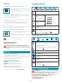
ELECTRONIC PUSHBUTTON PANEL
(GRUPPO INCASSO, Green Tech)
Motor ON/OFF
Upon start-up, the speed is that stored at the previous operation.
Increase speed from 1 to 4
Speed 4 is only active for a few
minutes, then speed 3 activa-
tes.
The speeds are indicated by the
LEDs on the keys:
Speed 1
Speed 2
Speed 3
Speed 4
("+" LED flashing)
Reduce speed from 4 to 1
Light on/o
Short impulse: turn light on and off
Long impulse: change light tone from 2700K to 5600K
TIMER (red LED flashing)
Auto switch-off after 15 min.
The function deactivates (red LED off) if:
- The TIMER key ( ) is pressed again.
- The ON/OFF key ( ) is pressed.
TOUCH PUSHBUTTON PANEL (GRUPPO INCASSO MURANO)
ON/OFF (Blue led steady on)
Motor on/off and Speed 1
ON/OFF (blue led ashing)
If pressed for more than 3 seconds, it activates the 24h cycle (1h ON
-> 3h
OFF -> 1h ON)
the function deactivates if:
- The motor turns off (key
)
- After 24h
Speed 2 activation
Speed 3 activation
Speed 4 is only active for a few minutes, then speed 3 activates.
Light on/o
Short impulse: turn light on and off
Long impulse: change light tone from 2700K to 5600K
TIMER (red LED flashing)
Auto switch-off after 15 min.
The function deactivates (red LED off) if:
- The motor turns off (key ).
- The speed is changed.
USING THE RADIO CONTROL
WARNINGS!:
Place the hood away from sources of electromagnetic waves (e.g.
microwave ovens), which could interfere with the radio control
and with the hood electronics.
The maximum operating distance is 5 metres, that may vary according to
the presence of electromagnetic interferences.
Radio control operated at 433.92MHz.
The radio control consists of two parts:
- the receiver built into the hood;
- the transmitter shown here in the gure.

17
ENGLISH
DESCRIPTION OF TRANSMITTING COMMANDS
UP
Motor switch-on and speed increase
from 1 to 4. Speed 4 is only active for a
few minutes.
DOWN
Speed decrease and motor switch-off.
Light ON-OFF
Short impulse:
turn light on and off
Long impulse:
change light tone from 2700K to 5600K
TIMER ON: The motor automatically
switches off after 15 min.
The function is automatically disabled if
the motor is switched off ( key)
Command transmission active
The radio control is optional for the GRUPPO INCASSO and Green Tech.
Follow the entire procedure described below if purchased.
Skip the activation procedure for IL GRUPPO INCASSO MURANO.
ACTIVATION PROCEDURE (for GRUPPO INCASSO and Green Tech)
Before using the radio control, follow the procedure below on the hood push-
button panel:
• Press LIGHT (
) and TIMER ( ) simultaneously until all LEDs start flashing.
• Release the two keys and press LIGHT (
) again until all LEDs are lit up.
• Release LIGHT (
): now the receiver is active.
This procedure is also used to deactivate the receiver.
RADIO CONTROL CODE CHANGE
With only one radio control, go directly to point 2.
With several radio controls in the same room, a new code can be created by
following the procedure below.
Disconnect the power to the hood before starting the procedure.
1 CREATE A NEW CODE
The procedure is to be carried out on the radio control.
• Press LIGHT and TIMER simultaneously until the display starts flashing.
• Press DOWN on the radio control: saving is confirmed by three brief flash-
es of the display. The new code cancels and replaces the previous default
code.
Reconnect the hood to the electrical power supply, making sure
that the lights and motor are o.
2A ASSOCIATING THE RADIO CONTROL WITH THE HOOD
USING THE ELECTRONIC PUSHBUTTON PANEL
press TIMER ( ) on the hood pushbutton panel for 2 seconds:
the red LED lights up.
press any key on the radio control within 10 seconds.
2B ASSOCIATING THE RADIO CONTROL WITH THE HOOD
USING THE TOUCH PUSHBUTTON PANEL
press LIGHT ( ) on the hood pushbutton panel for 2 seconds:
the red LED lights up.
press any key on the radio control within 10 seconds.
RESTORING DEFAULT CODE
the procedure is to be carried out if the hood is disposed of, sold or transferred.
Disconnect the power to the hood before starting the procedure.
• Press UP and DOWN simultaneously on the radio control for more
than 5 seconds: reset is confirmed by three brief flashes of the display.
• Reconnect the hood to the electrical power supply.
• Proceed with associating the hood and the radio control, as described in
point 2.
MAINTENANCE
Before cleaning or carrying out maintenance operations, discon-
nect the equipment by removing the plug or switching o the
main switch.
Do not use detergents containing abrasive, acidic or corrosive substances
or abrasive cloths.
Regular maintenance guarantees proper operation and performance over time.
Special attention is to be paid to the metal anti-grease lters : frequent clean-
ing of the filters and their supports ensures that no flammable grease is accu-
mulated.
CLEANING OF EXTERNAL SURFACES
You are advised to clean the external surfaces of the hood at least once every
15 days to prevent oily substances and grease from sticking to them. To clean
the brushed stainless steel hood, the Manufacturer recommends using "Magic
Steel" wipes.
Alternatively and for all the other types of surfaces, it can be cleaned using a
damp cloth, slightly moistened with mild, liquid detergent or denatured alcohol.
Complete cleaning by rinsing well and drying with soft cloths.
Do not use too much moisture or water around the push button
control panel and lighting devices in order to prevent humidity
from reaching electronic parts.
The glass panels can only be cleaned with specific, non-corrosive or non-abra-
sive detergents using a soft cloth.
The Manufacturer declines all responsibility for failure to comply with these in-
structions.
CLEANING OF INTERNAL SURFACES
Do not clean electrical parts, or parts related to the motor inside
the hood, with liquids or solvents.
For the internal metal parts, see the previous paragraph.
METAL ANTI-GREASE FILTERS
It is advised to frequently wash the metal filters (at least once a month) leaving
them to soak in boiling water and cleaning solution for 1 hour, taking care not
to bend them.
Do not use corrosive, acid or alkaline detergents.
Rinse them well and wait for them to be completely dry before reassembling
them.
Washing in a dishwasher is permitted, however, it may cause the filter material to
darken: to reduce the possibility of this problem from happening, use low-tem-
perature washes (55°C max.).
To extract and insert the metal anti-grease filters see the assembly instructions.
ACTIVE CARBON FILTERS
These filters retain the odours in the air that passes through them. The purified
air is recirculated into the environment.
The active carbon filters must be replaced on average every 3-4 months under
normal conditions of use.
See assembly instructions to replace the active carbon filters.

18
LIGHTING
The range hood is equipped with high efficiency, low consumption LED spotli-
ghts with an extremely long life-span under normal use conditions.
Should the LED spotlight need to be replaced, proceed as shown in the figure.
12V
3
1
2
DISPOSAL AFTER END OF USEFUL LIFE
The crossed-out trash or refuse bin symbol on the appliance means
that the product is WEEE, i.e. “Waste electrical and electronic equip-
ment'', accordingly it must not be disposed of with regular unsor-
ted waste (i.e. with ''mixed household waste''), but it must be disposed of sepa-
rately so that it can undergo specific processing for its re-use, or a specific
treatment, to remove and safely dispose of any substances that may be harmful
to the environment and remove the raw materials that can be recycled. Proper
disposal of these products contributes to saving valuable resources and avoid
potential negative effects on personal health and the environment, which may
be caused by inappropriate disposal of waste.
You are kindly asked to contact your local authorities for further information
regarding the designated waste collection points nearest to you. Penalties for
improper disposal of such waste can be applied in compliance with national
regulations.
INFORMATION ON DISPOSAL IN EUROPEAN UNION COUNTRIES
The EU WEEE Directive was implemented differently in each country, accordin-
gly, if you wish to dispose of this appliance we suggest contacting your local
authorities or dealer to find out what the correct method of disposal is.
INFORMATION ON DISPOSAL IN NONEUROPEAN UNION COUNTRIES
The crossed-out trash or refuse bin symbol is only valid in the European Union: if
you wish to dispose of this appliance in other countries, we suggest contacting
your local authorities or dealer to find out what the correct method of disposal is.
WARNING!
The Manufacturer reserves the right to make changes to the equipment at any
time and without prior notice. Printing, translation and reproduction, even par-
tial, of this manual are bound by the Manufacturer's authorisation.
Technical information, graphic representations and specifications in this manual
are for information purposes and cannot be divulged.
This manual is written in Italian. The Manufacturer is not responsible for any tran-
scription or translation errors.

19
DEUTSCH
ANWEISUNGEN FÜR DIE SICHERHEIT
UND WARNHINWEISE
Die Installation muss von kompetenten
und qualizierten Installateuren unter Be-
folgung der Angaben der vorliegenden Gebrau-
chsanweisung sowie unter Einhaltung der gültig-
en Sicherheitsvorschriften vorgenommen
werden.
Wenn das Versorgungskabel oder andere Kom-
ponenten beschädigt sind, darf die Abzugshaube
NICHT verwendet werden:
Die Abzugshaube von
der Stromversorgung trennen und den Händler oder
den autorisierten Kundendienst für die Reparatur
kontaktieren.
Die elektrische, mechanische und funktionelle Struktur
des Geräts darf nicht verändert werden.
Niemals versuchen, Reparaturen oder Austau-
schtätigkeiten selbst durchzuführen. Werden die-
se Arbeiten von Personen durchgeführt, die nicht
dazu befähigt und qualiziert sind, so kann dies
zu schweren Personen- und Sachschäden führen,
die von der Herstellergarantie nicht gedeckt sind.
HINWEISE FÜR DEN INSTALLATEUR
TECHNISCHE SICHERHEIT
Vor der Installation der Abzugshaube muss sicher-
gestellt werden, dass sämtliche Komponenten
unbeschädigt und funktionstüchtig sind. Sollten
Schäden festgestellt werden, nicht mit der Installation
fortfahren und umgehend den Händler kontaktieren.
Sollte ein ästhetischer Mangel festgestellt werden, so
darf die Abzugshaube NICHT installiert werden. Die
Abzugshaube wieder verpacken und umgehend den
Händler kontaktieren.
Sobald die Abzugshaube installiert ist, werden keine
Beanstandungen aufgrund ästhetischer Mängel mehr
akzeptiert.
Während der Installation ist immer eine geeignete
persönliche Schutzausrüstung zu tragen (z.B. Sicher-
heitsschuhwerk) und aufmerksam und korrekt vorzu-
gehen.
Das mit der Abzugshaube gelieferte Befestigungs-
set (Schrauben und Dübel) darf ausschließlich für
gemauerte Wände verwendet werden. Sollte es not-
wendig sein, die Abzugshaube an einer Wand aus
anderem Material zu installieren, müssen alternative
Befestigungssysteme in Betracht gezogen werden,
wobei die Festigkeit der Wand und das Gewicht der
Abzugshaube (siehe S. 2) zu berücksichtigen sind.
Dabei ist zu beachten, dass die Installation mit Befes-
tigungssystemen, die von den mitgelieferten abwei-
chen, elektrische Gefahren und Risiken in Bezug auf
die mechanische Abdichtung mit sich bringen kann.
Die Abzugshaube darf nicht in Außenbereichen in-
stalliert und keinen Witterungseinflüssen (Regen,
Wind, etc.) ausgesetzt werden.
ELEKTRISCHE SICHERHEIT
Die elektrische Anlage für den Anschluss der
Abzugshaube muss den geltenden Normen
entsprechen und mit einem Erdungssystem
ausgestattet sein, das den Sicherheitsvorschriften des
Installationslandes entspricht. Sie muss außerdem der
EU-Gesetzgebung bezüglich der Funkentstörung ent
-
sprechen.
Vor der Installation der Abzugshaube muss überprüft
werden, dass die Netzspannung derjenigen auf dem
Typenschild im Inneren der Abzugshaube entspricht.
Die für den elektrischen Anschluss verwendete Steck-
dose muss gut erreichbar sein, wenn das Gerät ins-
talliert ist. Andernfalls muss ein Hauptschalter vorge-
sehen werden, um die Abzugshaube bei Bedarf zu
trennen.
Sämtliche eventuellen Änderungen an der Elektroan-
lage müssen von einem qualifizierten Elektriker vor-
genommen werden.
Die Mindestlänge der Befestigungsschraube des Ka-
mins (vom Hersteller mitgeliefert) beträgt 13 mm. Die
Verwendung von Schrauben, die der vorliegenden
Gebrauchsanweisung nicht entsprechen, kann elek-
trische Gefahren mit sich bringen.
Im Fall einer Störung des Geräts nicht versuchen, das
Problem eigenständig zu lösen, sondern den Händler
oder den autorisierten Kundendienst für die Repara-
tur kontaktieren.
Während der Installation der Abzugshaube
muss das Gerät durch Ziehen des Netzsteckers
oder Betätigung des Hauptschalters abgeschaltet wer
-
den.
SICHERHEIT RAUCHABZUG
Das Gerät nicht an Rohre für den Abzug von
Rauch anschließen, der durch Verbrennung ent
-
steht (z.B. Heizkessel, Kamine, etc.).
Vor der Installation der Abzugshaube muss sicher-
gestellt werden, dass alle gültigen gesetzlichen Vor-
schriften in Bezug auf die Luftableitung aus dem
Raum eingehalten werden.
HINWEISE FÜR DEN BENUTZER
Diese Hinweise wurden für Ihre Sicherheit und
die Sicherheit anderer Personen erstellt, und
wir bitten Sie deshalb, die vorliegende Ge
-

20
brauchsanweisung vor der Installation, der Verwen-
dung oder der Reinigung des Geräts vollständig zu le-
sen.
Der Hersteller lehnt jegliche Haftung für etwaige di
-
rekte oder indirekte Schäden von Personen, Gegen-
ständen oder Haustieren ab, die durch eine Nichtbe-
achtung der in der vorliegenden Gebrauchsanweisung
angeführten Sicherheitshinweise verursacht werden.
Es ist sehr wichtig, dass diese Gebrauchsanweisung zu
-
sammen mit dem Gerät aufbewahrt wird, damit künf-
tig darin nachgelesen werden kann.
Falls das Gerät verkauft oder an eine andere Person
übergeben wird, muss sichergestellt werden, dass
auch die Gebrauchsanweisung übergeben wird, da-
mit der neue Besitzer informiert werden kann, wie die
Abzugshaube funktioniert und welche diesbezügli-
chen Warnhinweise zu beachten sind.
Nach der Installation der Edelstahlhaube muss als Ers-
tes deren Reinigung erfolgen, um die Rückstände der
Schutzklebefolie und eventuelle Flecken von Öl oder
Fett zu entfernen, die die Oberfläche der Abzugshau-
be unwiderruflich beschädigen können, falls sie nicht
entfernt werden. Für diesen Vorgang empfiehlt der
Hersteller, die mitgelieferten Reinigungstücher zu be-
nutzen, die auch gekauft werden können.
Immer die Verwendung von originalen Ersatzteilen
fordern.
VERWENDUNGSBESTIMMUNG
Das Gerät ist ausschließlich für die Absaugung von
Rauch bestimmt, der während der Zubereitung von
Speisen in Haushaltsküchen, nicht in gewerblichen
Küchen, erzeugt wird. Jede andere Verwendung gilt
als unsachgemäß, kann Schäden an Personen, Gegen
-
ständen und Haustieren verursachen und enthebt den
Hersteller von jeglicher Verantwortung.
Dieses Gerät kann von Kindern ab 8 Jahren sowie von
Personen mit reduzierten physischen, sensorischen
oder mentalen Fähigkeiten oder Mangel an Erfah-
rung und/oder Wissen benutzt werden, wenn sie
beaufsichtigt oder bezüglich des sicheren Gebrauchs
des Gerätes unterwiesen wurden und die damit zu-
sammenhängenden Gefahren verstanden haben.
Kinder dürfen nicht mit dem Gerät spielen. Kinder
dürfen die vom Benutzer auszuführende Reinigung
und Wartung nicht unbeaufsichtigt durchführen.
HINWEISE FÜR VERWENDUNG UND REINIGUNG
Vor jedem Reinigungs- oder Wartungseingri
das Gerät durch Ziehen des Netzsteckers oder
Betätigung des Hauptschalters vom Stromnetz
trennen.
Die Abzugshaube nicht mit nassen Händen oder
nackten Füßen verwenden.
Immer kontrollieren, dass alle elektrischen Teile (Be-
leuchtung, Absauganlage) ausgeschaltet sind, wenn
das Gerät nicht verwendet wird.
Das maximale Gesamtgewicht eventuell auf der Ab-
zugshaube abgestellter oder an ihr aufgehängter Ge-
genstände (falls vorgesehen) darf 1,5 kg nicht über-
schreiten.
Fritteusen müssen während des Betriebs überwacht
werden: Das erhitzte Öl könnte Feuer fangen.
Unter der Haube keine offenen Flammen verwenden.
Unterhalb der Abzugshaube keine Garvorgänge mit
"offenen" Flammen ausführen.
Die Abzugshaube nie ohne Metallfettfilter verwen-
den. In diesem Fall würden sich Fett und Schmutz auf
dem Gerät absetzen und seine Funktionstüchtigkeit
beeinträchtigen.
Die erreichbaren Teile der Abzugshaube können heiß
sein, wenn sie zusammen mit Kochgeräten verwen-
det werden.
Mit der Reinigung so lange warten, bis alle Teile der
Abzugshaube abgekühlt sind.
Sollte die Reinigung nicht gemäß den Vorschriften
und mit den Produkten ausgeführt werden, die im
vorliegenden Handbuch angegeben sind, so besteht
Brandgefahr.
Wenn das Gerät über einen längeren Zeitraum nicht
verwendet wird, muss der Hauptschalter abgeschal-
tet werden.
Bei gleichzeitiger Verwendung anderer mit Gas
oder anderen Brennstoen gespeister Verbrau
-
cher (Heizkessel, Öfen, Kamine, etc.) für eine an-
gemessene, vorschriftsmäßige Lüftung des Raumes
sorgen, in dem die Dunstabsaugung erfolgt.
INSTALLATION
Dieser Abschnitt ist ausschließlich qualiziertem Personal vorbehalten
Vor der Installation der Abzugshaube muss das Kapitel "ANWEISUNGEN
FÜR DIE SICHERHEIT UND WARNHINWEISE" aufmerksam gelesen wer-
den.
TECHNISCHE MERKMALE
Die technischen Daten des Geräts sind auf den Schildern im Inneren der Abzugs-
haube angegeben.
POSITIONIERUNG
Der Mindestabstand zwischen dem höchsten Teil des Kochgeräts und dem unters-
ten Teil der Abzugshaube ist in der Montageanleitung angegeben.
Wenn die Abzugshaube über einer Gaskochfläche positioniert ist, muss dieser
Abstand gewöhnlich mindestens 65 cm (25,6") betragen. Dennoch kann gemäß
der Auslegung der Norm EN60335-2-31 vom 11.07.2002 vonseiten der TC61
(subclause 7.12.1 meeting 15 agenda item 10.11) der Mindestabstand zwischen
der Kochebene und dem unteren Teil der Abzugshaube auf den in der Monta-
geanleitung angegebenen Wert vermindert werden.
Wenn die Anleitung der Gaskochebene einen größeren Abstand vorschreibt,
muss dies eingehalten werden.
Die Abzugshaube darf nicht in Außenbereichen installiert und keinen Witte-
rungseinflüssen (Regen, Wind, etc.) ausgesetzt werden.
Seite wird geladen ...
Seite wird geladen ...
Seite wird geladen ...
Seite wird geladen ...
Seite wird geladen ...
Seite wird geladen ...
Seite wird geladen ...
Seite wird geladen ...
Seite wird geladen ...
Seite wird geladen ...
Seite wird geladen ...
Seite wird geladen ...
Seite wird geladen ...
Seite wird geladen ...
Seite wird geladen ...
Seite wird geladen ...
Seite wird geladen ...
Seite wird geladen ...
Seite wird geladen ...
Seite wird geladen ...
Seite wird geladen ...
Seite wird geladen ...
Seite wird geladen ...
Seite wird geladen ...
Seite wird geladen ...
Seite wird geladen ...
Seite wird geladen ...
Seite wird geladen ...
Seite wird geladen ...
Seite wird geladen ...
Seite wird geladen ...
Seite wird geladen ...
Seite wird geladen ...
Seite wird geladen ...
Seite wird geladen ...
Seite wird geladen ...
Seite wird geladen ...
Seite wird geladen ...
Seite wird geladen ...
Seite wird geladen ...
Seite wird geladen ...
Seite wird geladen ...
Seite wird geladen ...
Seite wird geladen ...
Seite wird geladen ...
Seite wird geladen ...
Seite wird geladen ...
Seite wird geladen ...
Seite wird geladen ...
Seite wird geladen ...
Seite wird geladen ...
Seite wird geladen ...
Seite wird geladen ...
Seite wird geladen ...
Seite wird geladen ...
Seite wird geladen ...
-
 1
1
-
 2
2
-
 3
3
-
 4
4
-
 5
5
-
 6
6
-
 7
7
-
 8
8
-
 9
9
-
 10
10
-
 11
11
-
 12
12
-
 13
13
-
 14
14
-
 15
15
-
 16
16
-
 17
17
-
 18
18
-
 19
19
-
 20
20
-
 21
21
-
 22
22
-
 23
23
-
 24
24
-
 25
25
-
 26
26
-
 27
27
-
 28
28
-
 29
29
-
 30
30
-
 31
31
-
 32
32
-
 33
33
-
 34
34
-
 35
35
-
 36
36
-
 37
37
-
 38
38
-
 39
39
-
 40
40
-
 41
41
-
 42
42
-
 43
43
-
 44
44
-
 45
45
-
 46
46
-
 47
47
-
 48
48
-
 49
49
-
 50
50
-
 51
51
-
 52
52
-
 53
53
-
 54
54
-
 55
55
-
 56
56
-
 57
57
-
 58
58
-
 59
59
-
 60
60
-
 61
61
-
 62
62
-
 63
63
-
 64
64
-
 65
65
-
 66
66
-
 67
67
-
 68
68
-
 69
69
-
 70
70
-
 71
71
-
 72
72
-
 73
73
-
 74
74
-
 75
75
-
 76
76


Falmec GRUPPO INCASSO 50CM Bedienungsanleitung
- Kategorie
- Dunstabzugshauben
- Typ
- Bedienungsanleitung
- Dieses Handbuch eignet sich auch für
in anderen Sprachen
- English: Falmec GRUPPO INCASSO 50CM Owner's manual
- français: Falmec GRUPPO INCASSO 50CM Le manuel du propriétaire
- español: Falmec GRUPPO INCASSO 50CM El manual del propietario
- italiano: Falmec GRUPPO INCASSO 50CM Manuale del proprietario
- Nederlands: Falmec GRUPPO INCASSO 50CM de handleiding
- português: Falmec GRUPPO INCASSO 50CM Manual do proprietário
- dansk: Falmec GRUPPO INCASSO 50CM Brugervejledning
- svenska: Falmec GRUPPO INCASSO 50CM Bruksanvisning
Verwandte Artikel
-
Falmec Mercurio Evo Benutzerhandbuch
-
-
-
Falmec 0000279754 Bedienungsanleitung
-
-
-
-