Falmec Gruppo Incasso Kitchen Hood Benutzerhandbuch
- Typ
- Benutzerhandbuch

IT LIBRETTO ISTRUZIONI
UK INSTRUCTIONS BOOKLET
DE GEBRAUCHSANWEISUNG
FR MODE D'EMPLOI
ES MANUAL DE INSTRUCCIONES
RU ИНСТРУКЦИИ
PL INSTRUKCJA OBSŁUGI
NL HANDLEIDING
PT MANUAL DE INSTRUÇÕES
DK BRUGSANIVSNINGER
SE INSTRUKTIONSBOK
FI OHJEKIRJA
NO BRUKSANVISNING
gruppo incasso
gruppo incasso A+
gruppo incasso Murano
https://tm.by
Интернет-магазин TM.by

2
GRUPPO INCASSO 100
GRUPPO INCASSO 70
GRUPPO INCASSO 50
GRUPPO INCASSO 70 Murano
GRUPPO INCASSO 50 Murano
Gruppo incasso 100: 15 kg
Gruppo incasso 70: 12 kg
Gruppo incasso 50: 10 kg
Gruppo incasso Murano 70: 13 kg
Gruppo incasso Murano 50: 11 kg
800
m3/h
262
1053 / 776 / 531
294
93
150
780 / 502 / 257
319
259
263
min 12/max 20
1017 / 739 / 494
1029 / 751 / 506
IT - MISURE FORO PER INCASSO
UK - HOLE MEASUREMENTS FOR INSTALLATION
DE - LOCHABMESSUNGEN FÜR EINBAU
FR - MESURES DU TROU POUR ENCASTREMENT
ES - MEDIDAS DEL ORIFICIO PARA EMPOTRADO
RU -
PL - WYMIARY OTWORU DO ZABUDOWY
NL - MATEN GAT VOOR INBOUW
PT - MEDIDAS DO FURO PARA EMBUTIR
DK - MÅL TIL ÅBNING FOR INDBYGNING
SE - MÅTT HÅL FÖR INBYGGNAD
FI - AUKON MITAT UPOTUSTA VARTEN
NO - HULLMÅL FOR INNFELLING
https://tm.by
Интернет-магазин TM.by

ITALIANO
3
GRUPPO INCASSO A+ 70
GRUPPO INCASSO A+ 50
Gruppo incasso A+ 70: 13 kg
Gruppo incasso A+ 50: 11 kg
800
m3/h
751 / 506
262
739 / 494
293
502 / 257
396 / 273
776 / 531
294
150
93
319
259
294
263
IT - MISURE FORO PER INCASSO
UK - HOLE MEASUREMENTS FOR INSTALLATION
DE - LOCHABMESSUNGEN FÜR EINBAU
FR - MESURES DU TROU POUR ENCASTREMENT
ES - MEDIDAS DEL ORIFICIO PARA EMPOTRADO
RU -
PL - WYMIARY OTWORU DO ZABUDOWY
NL - MATEN GAT VOOR INBOUW
PT - MEDIDAS DO FURO PARA EMBUTIR
DK - MÅL TIL ÅBNING FOR INDBYGNING
SE - MÅTT HÅL FÖR INBYGGNAD
FI - AUKON MITAT UPOTUSTA VARTEN
NO - HULLMÅL FOR INNFELLING
https://tm.by
Интернет-магазин TM.by

4
Gruppo incasso 70: 12 kg
Gruppo incasso 50: 10 kg
751 / 506
739 / 494
262
776 / 531
294
120
74
502 / 257
259
263
337
min 12/max 20
GRUPPO INCASSO 70
GRUPPO INCASSO 50
600
m3/h
IT - MISURE FORO PER INCASSO
UK - HOLE MEASUREMENTS FOR INSTALLATION
DE - LOCHABMESSUNGEN FÜR EINBAU
FR - MESURES DU TROU POUR ENCASTREMENT
ES - MEDIDAS DEL ORIFICIO PARA EMPOTRADO
RU -
PL - WYMIARY OTWORU DO ZABUDOWY
NL - MATEN GAT VOOR INBOUW
PT - MEDIDAS DO FURO PARA EMBUTIR
DK - MÅL TIL ÅBNING FOR INDBYGNING
SE - MÅTT HÅL FÖR INBYGGNAD
FI - AUKON MITAT UPOTUSTA VARTEN
NO - HULLMÅL FOR INNFELLING
https://tm.by
Интернет-магазин TM.by

5
620
mm
MO
3
MO
Max 20 mm
Min 12 mm
21
2
3
IT - Misure installazione (1), foratura pensile (2),
inserimento cappa (3), ssaggio al pensile (4)
UK - Installation measurements (1), wall unit hole (2),
hood installation (3), tting to the wall unit (4)
DE - Installationsabmessungen (1), Bohrung Hängekasten (2),
Einfügen der Abzugshaube (3), Befestigung am Hängekasten (4)
FR -
Mesures pour installation (1), perçage meuble (2),
mise en place de la hotte (3), xation au meuble (4)
ES -
Medidas instalación (1), oricio armario de pared (2),
introducción campana (3), jación en el armario de pared (4)
RU -
(1),
(2), (3), (4)
PL - Wymiary instalacji (1), nawiercenie szafki wiszącej (2),
wsunięcie okapu (3), mocowanie do szafki wiszącej (4)
NL - Installatiematen (1), opening keukenkastje (2),
plaatsing kap (3), bevestiging aan het keukenkastje (4)
PT -
Medidas para a instalação (1), perfuração de elemento suspen-
so (2), inserção da coifa (3) e xação ao elemento suspenso (4)
DK - Installationsmål (1), hul i skab (2),
Isætning af emhætten (3), fastgørelse til skab (4)
SE - Mått installation (1), hål skåp (2),
insättning av kåpa (3), fastsättning i skåpet (4)
FI - Asennusmitat (1), hyllyn aukon teko (2),
liesituulettimen paikalleen asetus (3), kiinnitys hyllyyn (4)
NO - Installasjonsmål (1), boring i veggskap (2),
innsetting av ventilatorhette (3), festing til veggskap (4)
V1 (x4)
Only for
maint.
1
V1 (x4) V1 (x4)
OK!
23
NO!
4
1
MAGNET
https://tm.by
Интернет-магазин TM.by

6
M
ERM
ERM
1
4 5 6
2 3
ø 15
ø 12
600
m3/h
150mm
122mm
800
m3/h
5
6 7
800
m3/h
Only for
IT - Installazione valvola di non ritorno (5), tubo
di aspirazione (6) e collegamento elettrico (7)
UK - Installation of check valve (5), suction pipe (6)
and electrical connection (7)
DE - Installation des Rückschlagventils (5), des Absaug-
rohrs (6) und der elektrischen Verbindung (7)
FR - Installation clapet de non retour (5), tuyau
d'aspiration (6) et branchement électrique (7)
ES - Instalación de la válvula de no-retorno (5),
tubo de aspiración (6) y conexión eléctrica (7)
RU -
(5),
(6) (7)
PL - Instalacja zaworu zwrotnego (5), przewodu
zasysającego (6) i podłączenia elektrycznego (7)
NL - Installatie keerklep (5), afzuigbuis (6) en
elektrische aansluiting (7)
PT - Instalação da válvula de não retorno (5), tubo
de aspiração (6) e ligação elétrica (7)
DK - Installation af kontraventil (5), rør til udsug
(6) og elektrisk tilslutning (7)
SE - Installation av backventil (5), utsugningsrör
(6) samt elektrisk anslutning (7)
FI - Vastaventtiilin (5) asennus, imuputki (6) ja
sähköliitäntä (7)
NO - Installasjon av tilbakeslagsventil (5), innsu-
gingsrør (6) og elektrisk tilkobling (7)
https://tm.by
Интернет-магазин TM.by

7
3
1 2
600
m3/h
800
m3/h
8
9
10
IT - Montaggio ltro carbone attivo di serie: rimuovere pannello (8),
rimuovere ltri metallici (9), montare ltri carbone attivo (10).
EN - Assembling standard active carbon lter: remove panel (8), remove
metal lters (9), assemble active carbon lters (10).
DE - Montage des standardmäßigen Aktivkohlelters: Platte entfernen
(8), Metalllter entfernen (9), Aktivkohlelter montieren (10).
FR - Montage ltre au charbon actif standard : déposer le panneau (8), reti-
rer les ltres métalliques (9), monter les ltres au charbon actif (20).
ES - Montaje del ltro de carbón activo de serie: quite el panel (8), quite
los ltros metálicos (9), monte los ltros de carbón activo (10).
RU -
: (8), -
(9), (10).
PL - Montaż ltra z węglem aktywnym występującego w wyposażeniu seryjnym: zdjąć
panel (8), zdjąć metalowe ltry (9), zamontować ltry z węglem aktywnym (10).
NL - Montage serieel actief koolstolter: verwijder paneel (8), verwij-
der de metalen lters (9), monteer de actieve koolstolters (10).
PT - Montagem do ltro de carvão ativado de série: remover o painel (8), re-
mover os ltros metálicos (9) e montar os ltros de carvão ativado (10).
DK - Montage af medfølgende kullter: Fjern panelet (8), ern metall-
trene (9), monter de aktive kulltre (10).
SE - Montering av aktivt standardkollter: ta bort panelen (8), ta bort
metallfettltren (9), montera de aktiva kolltren (10).
FI - Sarjaan kuuluvan aktiivihiilisuodattimen asennus: poista levy (8), poista
metallisuodattimet (9), asenna aktiivihiilisuodattimet (10) paikalleen.
NO - Montering av standard aktivt kulllter: ern panelet (8), ern me-
tallltrene (9), monter de aktive kullltrene (10).
https://tm.by
Интернет-магазин TM.by

8
5
1
2 3 4
3
1 2
1
2
V1 (x4)
2
1
11
12 14
13
IT - Procedura di disinstallazione: rimuovere pannello (11),
rimuovere ltri metallici (12), svitare viti di tenuta(13),
sbloccare gruppo incasso (14).
EN - How to uninstall: remove panel (11), remove metal
lters (12), unscrew xing screws (13), release built-in
unit (14).
DE - Demontage-Methode: Platte entfernen (11), Metall-
lter entfernen (12), Dichtungsschrauben lösen (13),
Einbaugruppe freigeben(14).
FR - Procédure de désinstallation : déposer le panneau
(11), enlever les ltres métalliques (12), dévisser les vis
de xation (13), extraire le groupe à encastrement (14).
ES - Procedimiento de desmontaje: quite el panel (11), quite
los ltros metálicos (12), destornille los tornillos de
jación (13), desbloquee el grupo de empotrado (14).
RU - : (11),
(12),
(13), (14).
PL - Procedura dezinstalacji: zdjąć panel (11), zdjąć meta-
lowe ltry (12), odkręcić śruby przytrzymujące (13),
odblokować zespół do zabudowy (14).
NL - Demontageprocedure: verwijder het paneel (11), ver-
wijder de metalen lters (12), schroef de afdichtings-
schroeven (13) los, deblokkeer de inbouwgroep (14).
PT - Procedimento de desinstalação: remover o painel (11), re-
mover os ltros metálicos (12), desaparafusar os parafusos
de vedação(13) e desbloquear o grupo de embutir (14).
DK - Procedure for nedtagning: ern panelet (11), ern
metalltrene (12), skru skruerne, der holder emhætten
fast, løse (13), frigør enheden til indbygning (14).
SE - Procedur för avinstallation: ta bort panelen (11), ta
bort metallfettltren (12), skruva loss tätningsskru-
varna (13) och frigör den inbyggda enheten (14).
FI - Asennuksen purkaminen: poista levy (11), poista me-
tallisuodattimet (12), avaa kiinnitysruuvit (13), irrota
upotettu yksikkö (14).
NO - Prosedyre for avinstallering: ern panelet (11), ern
metallltrene (12), skru av holdeskruene (13), frigjør
innfellingsenheten (14).
IT - Staa di sicurezza (Tirare!)
EN - Safety bracket (Pull!)
DE -
Sicherungsbügel (Daran ziehen!)
FR - Patte de sécurité (Tirer !)
ES
- Abrazadera de seguridad (¡Tire!)
RU -
Предохранительный кронштейн (Потянуть!)
PL - Obejma zabezpieczająca (Pociągnąć!)
NL - Veiligheidsbeugel (Trekken!)
PT -
Suporte de segurança (Puxar!)
DK - Sikkerhedsstænger (Træk!)
SE - Säkerhetsfäste (Dra!)
FI - Turvavipu (Vedä!)
NO - Sikkerhetsbrakett (Trekk!)
https://tm.by
Интернет-магазин TM.by

ITALIANO
9
ISTRUZIONI DI SICUREZZA
E AVVERTENZE
Il lavoro d’installazione deve essere eseguito da installatori competenti e
qualicati, secondo quanto indicato nel presente libretto e rispettando le
norme in vigore.
Se il cavo di alimentazione o altri componenti sono danneggiati, la cappa NON deve
essere utilizzata: staccare la cappa dall'alimentazione elettrica e contattare il Rivenditore o
un Centro Assistenza Tecnica autorizzato per la riparazione.
Non modicare la struttura elettrica, meccanica e funzionale dell'apparecchiatura.
Non tentare di eettuare da soli riparazioni o sostituzioni: gli interventi eettuati da
persone non competenti e qualicate possono provocare danni, anche molto gravi, a
cose e/o persone non coperti da garanzia del Costruttore.
AVVERTENZE PER L'INSTALLATORE
SICUREZZA TECNICA
Prima di installare la cappa controllare l'integrità e funzionalità di ogni sua
parte: se si notano anomalie non procedere nell'installazione e contattare
il Rivenditore.
Nel caso sia stato riscontrato un difetto estetico la cappa NON deve essere installata;
riporla nel suo imballo originale e contattare il Rivenditore.
Una volta installata non sarà accettato alcun reclamo per difetti estetici.
Durante l'installazione utilizzare sempre mezzi di protezione personale (es.: scarpe antiinfor-
tunistiche) ed adottare comportamenti prudenti e corretti.
Il kit di ssaggio (viti e tasselli) fornito con la cappa è utilizzabile unicamente su pareti in mu-
ratura: in caso di installazione su pareti di materiale diverso, valutare altri sistemi di ssaggio
tenendo conto della resistenza del muro e del peso della cappa (indicato a pag. 2).
Tenere presente che l’installazione con sistemi di ssaggio diversi da quelli forniti o non
conformi può comportare rischi di natura elettrica e di tenuta meccanica.
Non installare la cappa in ambienti esterni e non esporla ad agenti atmosferici (pioggia,
vento, ecc...).
SICUREZZA ELETTRICA
L’impianto elettrico al quale viene collegata la cappa deve essere a norma
e munito di collegamento a terra secondo le norme di sicurezza del Paese
di utilizzo; deve essere inoltre conforme alle normative Europee sull’anti-
disturbo radio.
Prima di installare la cappa vericare che la tensione di rete corrisponda a quella riportata
dalla targhetta posta all’interno della cappa.
La presa usata per il collegamento elettrico deve essere facilmente raggiungibile con l’ap-
parecchiatura installata: in caso contrario, prevedere un interruttore generale per disconnet-
tere la cappa al bisogno.
Ogni eventuale modica all’impianto elettrico dovrà essere eseguita solo da un elettricista
qualicato.
La lunghezza massima della vite di ssaggio del camino (fornita dal fabbricante) è di 13
mm. L'utilizzo di viti non conformi con le presenti istruzioni può comportare rischi di natura
elettrica.
In caso di malfunzionamenti dell’apparecchio, non tentare di risolvere da soli il problema,
ma contattare il Rivenditore o un Centro di Assistenza autorizzato per la riparazione.
Durante l'installazione della cappa, disinserire l’apparecchio togliendo la
spina o agendo sull’interruttore generale.
SICUREZZA SCARICO FUMI
Non collegare l’apparecchio a condotti di scarico dei fumi prodotti dalla
combustione (ad es. caldaie, caminetti, ecc...)
Prima dell'installazione della cappa assicurarsi che siano rispettate tutte le normative vigenti
sullo scarico dell’aria all’esterno del locale.
AVVERTENZE PER L'UTILIZZATORE
Queste avvertenze sono state redatte per la vostra sicurezza e per quella
degli altri, Vi preghiamo, dunque, di leggere attentamente questo libretto
in tutte le sue parti prima di utilizzare l’apparecchio o di eettuare opera-
zioni di pulizia sullo stesso.
Il Costruttore declina ogni responsabilità per eventuali danni che possano, diretta-
mente o indirettamente, essere causati a persone, cose ed animali domestici con-
seguenti alla mancata osservanza delle avvertenze di sicurezza indicate in questo
libretto.
È molto importante che questo libretto istruzioni sia conservato insieme all’apparec-
chiatura per qualsiasi futura consultazione.
Se l’apparecchio dovesse essere venduto o trasferito ad un’altra persona, assicurarsi che an-
che il libretto venga fornito, in modo che il nuovo utente possa essere messo al corrente del
funzionamento della cappa e delle avvertenze relative.
Dopo l’installazione delle cappe in acciaio inox è necessario eseguire la pulizia della stessa
per rimuovere i residui di collante del protettivo e le eventuali macchie di grasso e oli, che,
se non rimosse, possono causare il deterioramento irreversibile della supercie della cappa.
Per questa operazione il costruttore raccomanda l’utilizzo delle salviette in dotazione, dispo-
nibili anche in acquisto
Esigere parti di ricambio originali.
DESTINAZIONE D'USO
L’apparecchio è destinato solo ed esclusivamente per l'aspirazione di fumi generati
dalla cottura di alimenti in ambito domestico, non professionale: qualsiasi utilizzo
diverso da questo è improprio, può provocare danni a persone, cose ed animali do-
mestici e solleva il Costruttore da qualsiasi responsabilità.
L’apparecchio può essere utilizzato da bambini di età non inferiore a 8 anni e da persone
con ridotte capacità siche, sensoriali o mentali, o prive di esperienza o della necessaria
conoscenza, purché sotto sorveglianza oppure dopo che le stesse abbiano ricevuto istru-
zioni relative all’uso sicuro dell’apparecchio e alla comprensione dei pericoli ad esso inerenti.
I bambini non devono giocare con l’apparecchio. La pulizia e la manutenzione a cura dell’u-
tilizzatore non deve essere eettuata da bambini senza sorveglianza.
AVVERTENZE PER L'UTILIZZO E LA PULIZIA
Prima di procedere a qualsiasi operazione di pulizia o di manutenzione,
disinserire l’apparecchio togliendo la spina o agendo sull’interruttore ge-
nerale.
Non utilizzare la cappa con le mani bagnate o piedi scalzi.
Quando l’apparecchio non viene usato, controllare sempre che tutte le parti elettriche, (luci,
aspiratore), siano spente.
Il peso massimo complessivo di eventuali oggetti posizionati o appesi (ove previsto) sulla
cappa non deve superare 1,5 Kg.
Controllare le friggitrici durante l’uso: I’olio surriscaldato potrebbe inammarsi.
Non accendere amme libere sotto la cappa.
Non preparare cibi alla amma sotto la cappa.
Non utilizzare mai la cappa senza i ltri metallici antigrasso; grasso e sporco in questo caso si
depositerebbero nell'apparecchio compromettendone il funzionamento.
Parti accessibili della cappa possono essere calde se utilizzate insieme con apparecchi di
cottura.
Non eettuare operazioni di pulizia quando parti della cappa sono ancora calde.
Se la pulizia non è condotta secondo le modalità e i prodotti indicati nel presente libretto è
possibile un rischio di incendio.
Disinserire l’interruttore generale quando l’apparecchio non viene utilizzato per periodi pro-
lungati di tempo.
In caso di utilizzo contemporaneo di altre utenze (caldaie, stufe, caminetti,
ecc.) alimentate a gas o con altri combustibili, provvedere ad una adegua-
ta ventilazione del locale in cui avviene l’aspirazione dei fumi, secondo le
norme vigenti.
INSTALLAZIONE
parte riservata solo a personale qualicato
Prima di eettuare l'installazione della cappa, leggere attentamente il
cap. "ISTRUZIONI DI SICUREZZA E AVVERTENZE".
CARATTERISTICHE TECNICHE
I dati tecnici dell'apparecchio sono riportati su etichette posizionate all’interno della cappa.
POSIZIONAMENTO
La distanza minima fra la parte più alta dell'apparecchiatura per la cottura e la parte
più bassa della cappa da cucina viene indicata nelle istruzioni di montaggio.
In generale, quando la cappa da cucina è posta su un piano cottura a gas, questa distan-
za deve essere almeno 65 cm (25,6"). Tuttavia sulla base di un’interpretazione della norma
EN60335-2-31 del 11-07-2002 da parte del TC61 (subclause 7.12.1 meeting 15 agenda item
10.11), la distanza minima tra piano cottura e parte inferiore della cappa può essere ridotta
alla quota riportata nelle istruzioni di montaggio.
Se le istruzioni del piano di cottura a gas specicano una distanza maggiore, bisogna te-
nerne conto.
Non installare la cappa in ambienti esterni e non esporla ad agenti atmosferici (pioggia,
vento, ecc...).
https://tm.by
Интернет-магазин TM.by

10
COLLEGAMENTO ELETTRICO
(parte riservata solo a personale qualicato)
Prima di eettuare qualsiasi operazione sulla cappa scollegare l’apparec-
chio dalla rete elettrica.
Assicurarsi che non vengano scollegati o tagliati li elettrici all’interno della
cappa:
in caso contrario contattare il Centro Assistenza più vicino.
Per l’allacciamento elettrico rivolgersi a personale qualicato.
Il collegamento deve essere eseguito in conformità con le disposizioni di legge in
vigore.
Prima di collegare la cappa alla rete elettrica, controllare che:
cappa;
posizionate all’interno della cappa);
superiori a 70 °C;
-
condo le norme vigenti;
la presa usata per il collegamento sia facilmente raggiungibile una volta installata la cappa.
In caso di :
-
zato”. Il li devono essere collegati come segue: giallo-verde per la messa a terra, blu per
il neutro e il lo marrone per la fase. La spina deve essere collegata ad un'adeguata presa
di sicurezza.
apparecchio sso non provvisto di cavo di alimentazione e di spina, o di altro dispositivo
che assicuri la disconnessione dalla rete, con una distanza di apertura dei contatti che
consenta la disconnessione completa nelle condizioni della categoria di sovratensione III.
Tali dispositivi di disconnessione devono essere previsti nella rete di alimentazione con-
formemente alle regole di installazione.
Il cavo di terra giallo/verde non deve essere interrotto dall’interruttore.
Il Costruttore declina ogni responsabilità nel caso le norme di sicurezza non vengano ri-
spettate.
SCARICO FUMI
CAPPA AD EVACUAZIONE ESTERNA ASPIRANTE
In questa versione, fumi e vapori vengono convogliati verso l'esterno
attraverso il tubo di scarico.
A tal ne, il raccordo d'uscita della cappa, deve essere collegato tramite
un tubo, ad un'uscita esterna.
Il tubo d'uscita deve avere:
condensa reuisca nel motore.
-
te della cappa.
E' necessario isolare la tubazione se passa attraverso ambienti freddi.
Per impedire ritorni d'aria dall'esterno, una valvola di non ritorno è presente in presenza
di motori con 800m3/h o superiori.
Deviazione per la Germania:
quando la cappa da cucina e apparecchi alimentati con energia diversa da quella elettrica sono
in funzione simultaneamente, la pressione negativa nel locale non deve superare i 4 Pa (4 x 10⁻⁵
bar).
CAPPA A RICICLO INTERNO FILTRANTE
In questa versione l’aria passa attraverso i ltri al carbone attivo per es-
sere puricata e riciclata nell’ambiente.
Controllare che i ltri al carbone attivo siano montati sulla cappa, in
caso negativo applicarli come indicato nelle istruzioni di montaggio.
In questa versione valvola di non ritorno non deve essere montata: rimuoverla se
presente sul raccordo di uscita aria del motore.
ISTRUZIONI DI MONTAGGIO
parte riservata solo a personale qualicato
La cappa ha la possibilità di essere installata in varie congurazioni.
Le fasi di montaggio generiche valgono per tutte le installazioni; seguire
invece dove specicato le fasi corrispondenti all’installazione desiderata.
FUNZIONAMENTO
QUANDO ACCENDERE LA CAPPA?
Accendere la cappa almeno un minuto prima di iniziare a cucinare per convogliare fumi e
vapori verso la supercie di aspirazione.
Al termine della cottura lasciare in funzione la cappa no a completa aspirazione di tutti i
vapori e odori: con la funzione Timer, è possibile impostare l'autospegnimento della cappa
dopo 15 minuti di funzionamento.
QUALE VELOCITÀ SCEGLIERE?
I velocità: mantiene l’aria pulita con bassi consumi di energia elettrica.
II velocità: condizioni normali di utilizzo.
III velocità: presenza di forti odori e vapori.
IV velocità: rapidi smaltimenti di odori e vapori.
QUANDO LAVARE O CAMBIARE I FILTRI?
I ltri metallici devono essere lavati ogni 30 ore di utilizzo.
I ltri carbone attivo, vanno sostituiti ogni 3-4 mesi a seconda dell’utilizzo della cappa.
Per ulteriori dettagli vedere cap “MANUTENZIONE”.
PULSANTIERA ELETTRONICA (GRUPPO INCASSO, A+)
Motore ON/OFF
All’avvio, la velocità è quella memorizzata al precedente spegnimento.
Incremento velocità da 1 a 4
Velocità 4 è attiva solo per alcuni mi-
nuti, poi si attiva velocità 3.
Le velocità sono segnalate dai led
presenti nei tasti:
Velocità 1
Velocità 2
Velocità 3
Velocità 4
(led "+" lampeggiante)
Riduzione velocità da 4 a 1
Accensione / spegnimento luce
TIMER (Led rosso lampeggiante)
Autospegnimento dopo 15min.
La funzione si disattiva (Led rosso spento) se:
- Si preme un'altra volta il tasto TIMER ( ).
- Si preme il tasto ON/OFF ( ).
ALLARME FILTRI (Led rosso sso con ( ) o)
Manutenzione ltri antigrasso dopo circa 30 ore di utilizzo.
Premere ( ) per 3 secondi per azzerare il contatore.
https://tm.by
Интернет-магазин TM.by

ITALIANO
11
PULSANTIERA TOUCH (GRUPPO INCASSO MURANO)
ON/OFF (led blu sso)
Accensione/spegnimento motore e Vel1
ON/OFF (led blu lampeggiante)
Premuto per più di 3 secondi attiva il ciclo 24h (1h ON -> 3h OFF -> 1h ON)
La funzione si disattiva se:
- si spegne il motore (tasto )
- Dopo 24h
Attivazione Velocità 2
Attivazione Velocità 3
Attivazione Velocità 4 solo per alcuni minuti, poi velocità 3
Accensione / spegnimento luce
TIMER (Led rosso lampeggiante)
Autospegnimento dopo 15min.
La funzione si disattiva (Led rosso spento) se:
- Si spegne il motore (tasto ).
- Si varia la velocità.
ALLARME FILTRI (Led rosso sso con motore OFF )
Manutenzione ltri antigrasso dopo circa 30 ore di utilizzo.
Premere per 3 secondi per azzerare il contatore.
UTILIZZO DEL RADIOCOMANDO
AVVERTENZE!:
Posizionare la cappa lontano da sorgenti di onde elettromagnetiche (es.
forni a microonde) che potrebbero interferire con il radiocomando e con
l’elettronica della cappa.
La distanza massima di funzionamento è di 5 metri che può variare in difetto in pre-
senza di interferenze elettromagnetiche.
Radiocomando operante a 433,92MHz.
Il radiocomando è composto da due parti:
- la ricevente integrata nella cappa;
- la trasmittente mostrata qui in gura.
DESCRIZIONE COMANDI TRASMITTENTE
UP
Accensione motore e incremento velocità
da 1 a 4. La quarta velocità è attiva solo per
alcuni minuti.
DOWN
Decremento velocità e spegnimento mo-
tore
Luce ON-OFF
TIMER ON: Autospegnimento del motore
dopo 15min.
La funzione si disattiva automaticamente se
si spegne il motore (tasto )
Trasmissione comando attiva
Il radiocomando è opzionale per il GRUPPO INCASSO e A+.
In caso di acquisto, seguire per intero la procedura descritta qui sotto.
Per IL GRUPPO INCASSO MURANO, saltare la procedura di attivazione.
PROCEDURA DI ATTIVAZIONE (per GRUPPO INCASSO e A+)
Prima di utilizzare il radiocomando, eseguire la seguente procedura sulla pulsantiera della
cappa:
• Premere contemporaneamente i tasti LUCE ( ) e TIMER ( ) no a che tutti i led inizia-
no a lampeggiare.
• Rilasciare i due tasti e premere ancora il tasto LUCE ( ) no a quando tutti i led saranno
accesi.
• Rilasciare il tasto LUCE ( ): adesso la ricevente è attiva.
La procedura serve anche per la disattivazione della ricevente.
CAMBIO CODICE RADIOCOMANDO
In presenza di un solo radiocomando passare direttamente al punto 2.
In presenza di più radiocomandi nella stessa stanza, è possibile generare un nuovo codice
con la seguente procedura.
Togliere alimentazione alla cappa prima di eettuare la procedura.
1 GENERARE UN NUOVO CODICE
La procedura va eseguita sul radiocomando.
• Premere contemporaneamente i tasti LUCE e TIMER no a che il display inco-
mincia a lampeggiare.
• Premere il tasto DOWN del radiocomando: la memorizzazione del nuovo codice è
confermata da 3 brevi lampeggi del display. Il nuovo codice annulla e sostituisce il prece-
dente codice di fabbrica.
Ricollegare la cappa alla rete elettrica, vericando che luci e motore siano
spenti.
2A ASSOCIAZIONE DEL RADIOCOMANDO ALLA CAPPA
CON PULSANTIERA ELETTRONICA
premere il tasto TIMER ( ) della pulsantiera della cappa per 2 secondi:
il led rosso si accende.
premere un tasto qualsiasi del radiocomando entro 10 secondi.
2B ASSOCIAZIONE DEL RADIOCOMANDO ALLA CAPPA
CON PULSANTIERA TOUCH
premere il tasto LUCE ( ) della pulsantiera della cappa per 2 secondi:
il led rosso si accende.
premere un tasto qualsiasi del radiocomando entro 10 secondi.
RIPRISTINO CODICE DI FABBRICA
la procedura è da eettuarsi in caso di cessione della cappa.
Togliere alimentazione alla cappa prima di eettuare la procedura.
• Premere contemporaneamente i tasti UP e DOWN del radiocomando per più di
5 secondi: l'avvenuto ripristino viene confermato da tre brevi lampeggi del display.
• Ricollegare la cappa alla rete elettrica.
• Procedere con l’associazione tra cappa e radiocomando come descritto nel punto 2.
https://tm.by
Интернет-магазин TM.by

12
MANUTENZIONE
Prima di procedere a qualsiasi operazione di pulizia o di manutenzione,
disinserire l’apparecchio togliendo la spina o agendo sull’interruttore ge-
nerale.
Non si devono utilizzare detergenti contenenti sostanze abrasive, acide o
corrosive e panni con superci ruvide.
Una costante manutenzione garantisce un buon funzionamento e rendimento nel tempo.
Particolari attenzioni vanno rivolte ai ltri metallici antigrasso: la pulizia frequente dei ltri
e dei loro supporti garantisce che non si accumulino grassi inammabili.
PULIZIA SUPERFICI ESTERNE
Si raccomanda di pulire le superci esterne della cappa almeno ogni 15 giorni per evitare
che le sostanze oleose o grasse possano intaccarle. Per la pulizia della cappa, realizzata in
acciaio inox spazzolato, il Costruttore consiglia l'utilizzo delle salviette "Magic Steel" che si
possono anche ordinare on-line sul sito www.e-falmec.com.
In alternativa e per tutti gli altri tipi di superci, la pulizia va eseguita usando un panno
umido leggermente imbevuto di detersivo neutro liquido o con alcool denaturato.
Terminare la pulizia con un accurato risciacquo e asciugatura con panni morbidi.
Non utilizzare troppa acqua in prossimità della pulsantiera e dei dispositi-
vi di illuminazione per evitare che l'umidità raggiunga parti elettroniche.
La pulizia dei pannelli in vetro va eseguita solo con detergenti specici non corrosivi o abra-
sivi utilizzando un panno morbido.
Il Costruttore declina ogni responsabilità qualora non vengano rispettate tali istruzioni.
PULIZIA SUPERFICI INTERNE
E’ vietata la pulizia di parti elettriche o parti relative al motore all’interno
della cappa, con liquidi o solventi.
Per le parti metalliche interne vedi paragrafo precedente.
FILTRI METALLICI ANTIGRASSO
Si consiglia di lavare frequentemente i ltri metallici (almeno ogni mese) lasciandoli in
ammollo per circa 1 ora in acqua bollente con detersivo per piatti, evitando di piegarli.
Non usare detergenti corrosivi, acidi o alcalini.
Risciacquarli con cura ed attendere che siano ben asciutti prima di rimontarli.
Il lavaggio in lavastoviglie è permesso, ma potrebbe creare imbrunimenti al materiale dei
ltri: per ridurre questo inconveniente utilizzare lavaggi a basse temperature (55°C max.).
Per l’estrazione e l'inserimento dei ltri metallici antigrasso vedi istruzioni di montaggio.
FILTRI AL CARBONE ATTIVO
Questi ltri trattengono gli odori presenti nell’aria che li attraversa. L’aria depurata viene così
rimessa nell’ambiente.
I ltri al carbone attivo devono essere sostituiti mediamente ogni 3-4 mesi in condizioni di
utilizzo normale.
Per la sostituzione dei ltri al carbone attivo vedi istruzioni di montaggio.
ILLUMINAZIONE
durata molto elevata in condizioni di normale utilizzo.
Nel caso si rendesse necessaria la sostituzione del faretto procedere come in gura.
12V
3
1
2
SMALTIMENTO A FINE VITA
Il simbolo del cestino barrato riportato sull’apparecchiatura in suo possesso indi-
ca che il prodotto è un RAEE, cioè un “Riuto derivante dalle Apparecchiature
Elettriche ed Elettroniche” e pertanto non deve essere gettato nella spazzatu-
ra indierenziata
separatamente così da essere sottoposto ad apposite operazioni per il suo riutilizzo, oppure
a uno specico trattamento, per rimuovere e smaltire in modo sicuro le eventuali sostanze
dannose per l’ambiente ed estrarre le materie prime che possono essere riciclate. Lo smalti-
mento corretto di questo prodotto contribuirà a salvare preziose risorse ed evitare potenzia-
li eetti negativi per la salute umana e per l’ambiente, che potrebbero essere causati da uno
smaltimento inappropriato dei riuti.
Vi preghiamo di contattare le autorità locali per ulteriori dettagli sul punto di smaltimento
designato più vicino. Potrebbero venire applicate delle penali per lo smaltimento scorretto
di questi riuti in conformità alla legislazione nazionale.
INFORMAZIONI SULLO SMALTIMENTO IN ITALIA
In Italia le apparecchiature RAEE devono perciò essere consegnate:
- ai Centri di Raccolta (chiamati anche isole ecologiche o piattaforme ecologiche) allestiti
dai Comuni o dalle Società di igiene urbana (in molte località viene anche eettuato il
servizio di ritiro a domicilio delle apparecchiature RAEE ingombranti);
- al negozio presso il quale si acquista una nuova apparecchiatura, che è tenuto a ritirarle
uno contro uno”);
- ad un negozio qualunque*, che è tenuto a ritirarle gratuitamente e senza obbligo di
uno contro zero”).
In questo caso:
-
sioni” (altezza, profondità e larghezza minori di 25 cm);
* 2) il negozio al quale viene riconsegnata l’apparecchiatura RAEE deve avere una supercie
di vendita superiore a 400 mq.
INFORMAZIONI SULLO SMALTIMENTO IN NAZIONI DELL'UNIONE EUROPEA
La Direttiva comunitaria sulle apparecchiature RAEE è stata recepita in modo diverso da
ciascuna nazione, pertanto se si desidera smaltire questa apparecchiatura suggeriamo di
contattare le autorità locali o il Rivenditore per chiedere il metodo corretto di smaltimento.
INFORMAZIONI SULLO SMALTIMENTO IN NAZIONI NON APPARTENENTI ALL'UNIO
NE EUROPEA
Il simbolo del cestino barrato è valido solamente nell’Unione Europea: se si desidera smaltire
questa apparecchiatura in altri Paesi suggeriamo di contattare le autorità locali o il Rivendi-
tore per chiedere il metodo corretto di smaltimento.
ATTENZIONE!
Il Costruttore si riserva il diritto di apportare modiche alle apparecchiature in qualsiasi
momento e senza preavviso. La stampa, la traduzione e la riproduzione anche parziale del
presente manuale s’intendono vincolate dall’autorizzazione del Costruttore.
Le informazioni tecniche, le rappresentazioni grache e le speciche presenti in questo ma-
nuale sono indicative e non divulgabili.
La lingua di stesura del manuale è l’italiano, il Costruttore non si rende responsabile per
eventuali errori di trascrizione o traduzione.
https://tm.by
Интернет-магазин TM.by

ITALIANO
13
GARANZIA (solo per l'Italia)
La sua nuova apparecchiatura è coperta da garanzia. Le condizioni di garanzia sono riporta-
te per esteso nel paragrafo successivo.
La casa costruttrice non risponde delle possibili inesattezze, imputabili ad
errori di stampa o di trascrizione, contenute nel presente libretto.
Si riserva di apportare ai propri prodotti quelle modiche che ritenesse
necessarie o utili, anche nell’interesse dell’utenza, senza pregiudicare le
caratteristiche essenziali di funzionalità e di sicurezza.
CONDIZIONI DI GARANZIA (solo per l'Italia)
IMPORTANTE!
La presente garanzia è valida solo per l’Italia (Guarantee conditions are
valid only for Italy).
DECRETO LEGISLATIVO DEL 30/06/2003 N. 196 - ART. 7
Codice in materia di protezione dei dati personali.
1. L’interessato ha diritto di ottenere la conferma dell’esistenza o meno di dati personali
che lo riguardano, anche se non ancora registrati, e la loro comunicazione in forma
intelleggibile.
2. L’interessato ha diritto di ottenere l’indicazione:
a) dell’origine dei dati personali;
b) delle nalità e modalità del trattamento;
c) della logica applicata in caso di trattamento eettuato con l’ausilio di strumenti elet-
tronici;
d) degli estremi identicativi del titolare, dei responsabili e del rappresentante designa-
to ai sensi dell’articolo 5, comma 2;
e) dei soggetti o delle categorie di soggetti ai quali i dati personali possono essere co-
municati o che possono venirne a conoscenza in qualità di rappresentante designato
nel territorio dello Stato, di responsabili o incaricati.
3. L’interessato ha diritto di ottenere:
a) l’aggiornamento, la retticazione ovvero, quando vi ha interesse, l’integrazione dei
dati;
b) la cancellazione, la trasformazione in forma anonima o il blocco dei dati trattati in
violazione di legge, compresi quelli di cui non è necessaria la conservazione in relazione
agli scopi per i quali i dati sono stati raccolti o successivamente trattati;
c) l’attestazione che le operazioni di cui alle lettere a) e b) sono state portate a cono-
scenza, anche per quanto riguarda il loro contenuto , di coloro ai quali i dati sono stati
comunicati o diusi, eccettuato il caso in cui tale adempimento si rileva impossibile o
comporta un impiego di mezzi manifestamente sproporzionato rispetto al diritto tute-
lato.
4. L’interessato ha diritto di opporsi, in tutto o in parte:
a) per motivi legittimi al trattamento dei dati personali che lo riguardano, ancorché
pertinenti allo scopo della, raccolta;
b) al trattamento di dati personali che lo riguardano a ni di invio di materiale pubblici-
tario o di vendita diretta o per il compimento di ricerche di mercato o di comunicazione
commerciale.
Titolare del trattamento dei dati è Falmec S.P.A.
Via dell’Artigianato, 42 - Vittorio Veneto (TV).
CONDIZIONI DI GARANZIA
• L’apparecchio è garantito dalla Casa costruttrice Falmec S.p.A (www.falmec.com) per un
periodo di 24 mesi dalla data del suo acquisto comprovata da ricevuta scale o altro
documento reso scalmente obbligatorio.
• La garanzia sarà prestata con la sostituzione o riparazione gratuita delle parti che risultino
difettose per vizi delle stesse imputabili a Falmec S.p.A..
• Non sono coperte dalla presente garanzia tutte le parti che dovessero risultare difetto-
se, danneggiate e/o viziate a causa di uso improprio dell’apparecchio, di negligenza o
trascuratezza nell’uso (mancata osservanza delle istruzioni per il funzionamento dell’ap-
parecchio), di inesatta installazione, di mancata ovvero errata manutenzione, di manu-
tenzioni operate da personale non autorizzato, di danni da trasporto, ovvero per circo-
stanze non riferibili a difetti di funzionamento imputabili a Falmec S.p.A. e/o comunque
direttamente imputabili alla Casa costruttrice. Si precisa inoltre che non rientrano nelle
prestazioni in garanzia gli interventi inerenti l’installazione e l’allacciamento agli impianti
elettrici e/o di alimentazione.
• Vengono peraltro esclusi dalla presente garanzia i componenti dell’apparecchio soggetti
ad usura, quali specicatamente ma non esaustivamente: lampadine di varie tipologie,
ltri metallici, ltri carbone, ecc.
• La Casa costruttrice declina ogni responsabilità per eventuali danni che possono, diret-
tamente o indirettamente, essere causati a persone, cose ed animali domestici in con-
seguenza alla mancanza di tutte le prescrizioni indicate nell’apposito libretto istruzioni
e concernenti, specialmente, le avvertenze in tema di installazione, uso e manutenzione
dell’apparecchio.
• Trascorsi i 24 mesi, l’apparecchio non sarà più coperto da garanzia e l’assistenza verrà pre-
stata addebitando le parti sostituite, le spese di manodopera e di trasporto dei personale
e dei materiali, secondo le tarie vigenti in possesso dei personale dei Servizio Assistenza
Tecnica autorizzato dalla Casa costruttrice. In presenza di un intervento eettuato pres-
so un Centro Assistenza Tecnica autorizzato, l’apparecchio vi sarà recapitato a spese e
rischio dell’utente.
• La presente garanzia è valida per la fornitura ed installazione dell’apparecchio avvenuta
nel solo territorio italiano.
Titolare del trattamento dei dati è Falmec S.P.A.
Via dell’Artigianato, 42 - Vittorio Veneto (TV).
CERTIFICATO DI GARANZIA SOLO PER ITALIA DA CONSERVARE
Questo certicato di garanzia non deve essere spedito, ma conservato con la ricevuta scale, o altro documento reso scalmente obbligatorio, che comprovi la data
d’acquisto della cappa. In caso necessiti intervenire per anomalie di funzionamento, si prega di contattare un Centro di Assistenza Tecnica autorizzato, tenendo a
portata di mano i dati sotto indicati:
Matricola/Serial Number (vedere ultima pagina libretto o targhetta dei dati tecnici posta all'interno della cappa):
È ASSOLUTAMENTE NECESSARIO INDICARE IL NUMERO MATRICOLA DELLA CAPPA.
Questo apparecchio viene garantito per 2 anni dalla data di acquisto contro difetti di materiale e/o di fabbricazione.
Questo certicato è valido e operante solo se conservato assieme alla ricevuta scale o altro documento reso scalmente obbligatorio.
Rivenditore:
Città:
Data d’acquisto:
https://tm.by
Интернет-магазин TM.by

14
SAFETY INSTRUCTIONS
AND WARNINGS
Installation operations are to be carried out by skilled and qualied in-
stallers in accordance with the instructions in this booklet and in compli-
ance with the regulations in force.
DO NOT use the hood if the power supply cable or other components are damaged:
disconnect the hood from the electrical power supply and contact the Dealer or an author-
ised Servicing Dealer for repairs.
Do not modify the electrical, mechanical or functional structure of the equipment.
Do not personally try to carry out repairs or replacements. Interventions carried out
by incompetent and unauthorised persons can cause serious damage to the unit or
physical and personal harm, not covered by the Manufacturer's warranty.
WARNINGS FOR THE INSTALLER
TECHNICAL SAFETY
Before installing the hood, check the integrity and function of each part.
Should anomalies be noted, do not proceed with installation and contact
the Dealer.
Do NOT install the hood if an aesthetic (or cosmetic) defect has been detected. Put it
back into its original package and contact the dealer.
No claim can be made for aesthetic (or cosmetic) defects once it has been installed.
During installation, always use personal protective equipment (e.g.: Safety shoes) and adopt
prudent and proper conduct.
The installation kit (screws and plugs) supplied with the hood is only to be used on masonry
walls: in case of installation on walls of a dierent material, assess other installation options
keeping in mind the type of wall surface and the weight of the hood (indicated on page 2).
Keep in mind that installations with dierent types of fastening systems from those sup-
plied, or which are not compliant, can cause electrical and mechanical seal danger.
Do not install the hood outdoors and do not expose it to atmospheric elements (rain, wind,
etc.).
ELECTRICAL SAFETY
The electrical system to which the hood is to be connected must be in ac-
cordance with local standards and supplied with earthed connection in
compliance with safety regulations in the country of use. It must also com-
ply with European standards regarding radio antistatic properties.
Before installing the hood, check that the electrical mains power supply corresponds with
what is reported on the identication plate located inside the hood.
The socket used to connect the installed equipment to the electrical power supply must
be within reach: otherwise, install a mains switch to disconnect the hood when required.
Any changes to the electrical system must be carried out by a qualied electrician.
The maximum length of the ue fastening screws (supplied by the manufacturer) must be
13 mm. Use of non-compliant screws with these instructions can lead to danger of an elec-
trical nature.
Do not try to solve the problem yourself in the event of equipment malfunction, but contact
the Dealer or an authorised Servicing Department for repairs.
When installing the hood, disconnect the equipment by removing the
plug or switching o the main switch.
FUMES DISCHARGE SAFETY
Do no connect the equipment to discharge pipes of fumes produced from
combustion (for example boilers, replaces, etc.).
Before installing the hood, ensure that all standards in force regarding discharge of air out of
the room have been complied with.
USER WARNINGS
These warnings have been drawn up for your personal safety and those of
others. You are therefore kindly asked to read the booklet carefully in its
entirety before using the or cleaning the equipment.
The Manufacturer declines all responsibility for any damage caused directly, or in-
directly, to persons, things and pets as a consequence of failing to comply with the
safety warnings indicated in this booklet.
It is imperative that this instructions booklet is kept together with the equipment for
any future consultation.
If the equipment is sold or transferred to another person, make sure that the booklet is
also supplied so that the new user can be made aware of the hood's operation and relative
warnings.
After the stainless steel hood has been installed, it will need to be cleaned to remove any
residues remaining from the protection adhesive as well as any grease and oil stains which, if
not removed, can cause irreversible damage to the hood surface. To properly clean the unit,
the manufacturer recommends using the supplied moist wipes, which are also available
sold separately.
Insist on original spare parts.
INTENDED USE
The equipment is solely intended to be used to extract fumes generated from cook-
ing food in non-professional domestic kitchens: any other use is improper. Improper
use can cause damage to persons, things, pets and exempts the Manufacturer from
any liability.
The equipment can be used by children over the age of 8 and by persons with reduced
physical, sensory and mental abilities, or with no experience or knowledge, as long as they
do so under supervision or after having received relative instructions regarding safe use of
the equipment and understanding of the dangers connected to it.
Children are not to play with the equipment. Cleaning and maintenance by the user must
not be carried out by children without supervision.
USE AND CLEANING WARNINGS
Before cleaning or carrying out maintenance operations, disconnect the
equipment by removing the plug or switching o the main switch.
Do not use the hood with wet hands or bare feet.
Always check that all electrical parts (lights, extractor fan) are o when the equipment is
not being used.
The maximum overall weight of any objects placed or hung (if applicable) on the hood must
not exceed 1.5 Kg.
Always supervise the cooking process during the use of deep-fryers: Overheated oil can
catch re.
Do not leave open, unattended ames under the hood.
Do not prepare food over an open ame under the hood.
Never use the hood without the metal anti-grease lters: in this case, grease and dirt will
deposit in the equipment and compromise its operation.
Accessible parts of the hood can be hot when used at the same time as the cooking ap-
pliances.
Do not carry out any cleaning operations when parts of the hood are still hot.
There can be a risk of re if cleaning is not carried out according to the instructions and
products indicated in this booklet.
Disconnect the main switch when the equipment is not used for long periods of time.
If other appliances that use gas or other fuels are being used at the same
time (boiler, stove, replaces, etc.), make sure the room where the fumes
are discharged is well-ventilated, in compliance with the local regulations.
INSTALLATION
only intended for qualied personnel
Before installing the hood, carefully read the chapter 'SAFETY IN-
STRUCTIONS AND WARNINGS'.
TECHNICAL FEATURES
The technical specications are exhibited on the labels located inside the hood.
POSITIONING
The minimum distance between the highest part of the cooking equipment and the
lowest part of the hood is indicated in the installation instructions.
Generally, when the hood is placed over gas cookers, the distance must be at least 65 cm
(25.6''). However, according to an interpretation of standard EN60335-2-31 dated 11-07-
2002 of TC61 (sub-clause 7.12.1 meeting 15 agenda item 10.11), the minimum distance
between the cooker and lower part of the hood can be reduced to the quota reported in
the installation instructions.
Should the instructions for the gas cooker specify a greater distance, this must be taken
into consideration.
Do not install the hood outdoors and do not expose it to outdoor environment (rain, wind,
etc.).
https://tm.by
Интернет-магазин TM.by

15
ENGLISH
ELECTRICAL CONNECTION
(only intended for qualied personnel)
Disconnect the equipment from electrical mains power supply before carry-
ing out any operations on the hood.
Ensure that the wires inside the hood are not disconnected or cut:
in the event of damage, contact your nearest Servicing Department.
Refer to qualied personnel for electrical connections.
Connection must be carried out in compliance with the provisions of law in force.
Before connecting the hood to the electrical mains power supply, check that:
hood;
-
cations located inside the hood);
-
ing 70 °C;
with regulations in force;
the socket used to connect the hood is within reach.
In case of:
The wires must be connected as follows: yellow-green for earthing, blue for neutral and
brown for the phase. The plug must be connected to an adequate safety socket.
xed equipment not provided with a power supply cable and plug, or any other device
that ensures disconnection from the electrical mains, with an opening gap of the con-
tacts that enables total disconnection in overvoltage category III conditions.
Said disconnection devices must be provided in the mains power supply in compliance
with installation regulations.
The yellow/green earth cable must not be cut o by the switch.
The Manufacturer declines all responsibility for failure to comply with the safety regulations.
FUMES DISCHARGE
EXTERNAL EXHAUST HOOD SUCTION
In this version the fumes and vapours are discharged outside through
the exhaust pipe.
To this end, the hood outlet tting must be connected via a pipe, to an
external output.
The outlet pipe must have:
owing back into the motor.
the hood.
You are required to insulate the pipes if it passes through cold environments.
In the presence of motors with 800m3/h or higher, a check valve is present to prevent
external air owing back.
Deviation for Germany:
when the kitchen hood is used at the same time as appliances that are powered by energy other
than electricity, the negative pressure in the room must not exceed 4 Pa (4 x 10⁻⁵ bar).
HOOD WITH INTERNAL RECIRCULATION FILTERING
In this model, the air passes through the charcoal lters to be puried
and recycled in the environment.
Ensure that the active carbon lters are assembled into the hood, if not,
install them as indicated in the assembly instructions.
In this version the check valve must not be assembled: remove it if it is on the air
outlet tting of the motor.
ASSEMBLY INSTRUCTIONS
only intended for qualied personnel
The hood can be installed in various congurations.
The generic assembly steps apply to all installations; for each case, follow
the specic steps provided for the required installation.
OPERATION
WHEN TO TURN ON THE HOOD?
Switch on the hood at least one minute before starting to cook to direct fumes and vapours
towards the suction surface.
After cooking, leave the hood operating until complete extraction of all vapours and odours.
By means of the Timer function, it is possible to set auto switch-o function which will allow
the hood to turn o automatically after 15 minutes of operation.
WHICH SPEED IS TO BE SELECTED?
1st speed: maintains the circulation of clean air with low electricity consumption.
2nd speed: normal conditions of use.
3rd speed: presence of strong odours and vapours.
4th speed: rapid disposal of odours and vapours.
WHEN SHOULD THE FILTERS BE WASHED OR REPLACED?
The metal lters must be cleaned every 30 hours of operation.
The active carbon lters must be replaced every 3-4 months, depending on the use of the
hood.
For further details see the “MAINTENANCE” chap.
ELECTRONIC PUSHBUTTON PANEL (GRUPPO INCASSO, A+)
Motor ON/OFF
Upon start-up, the speed is that stored at the previous operation.
Increase speed from 1 to 4
Speed 4 is only active for a few min-
utes, then speed 3 activates.
The speeds are indicated by the LEDs
on the keys:
Speed 1
Speed 2
Speed 3
Speed 4
("+" LED ashing)
Reduce speed from 4 to 1
Light on/o
TIMER (red LED ashing)
Auto switch-o after 15 min.
The function deactivates (red LED o) if:
- The TIMER key ( ) is pressed again.
- The ON/OFF key ( ) is pressed.
FILTER ALARM (red LED steady on with ( ) o)
Anti-grease lter maintenance after approximately 30 hours of operation.
Press ( ) the meter for 3 seconds to reset.
https://tm.by
Интернет-магазин TM.by

16
TOUCH PUSHBUTTON PANEL (GRUPPO INCASSO MURANO)
ON/OFF (Blue led steady on)
Motor on/o and Speed 1
ON/OFF (blue led ashing)
If pressed for more than 3 seconds, it activates the 24h cycle (1h ON -> 3h
OFF -> 1h ON)
the function deactivates if:
- The motor turns o (key )
- After 24h
Speed 2 activation
Speed 3 activation
Speed 4 is only active for a few minutes, then speed 3
activates.
Light on/o
TIMER (red LED ashing)
Auto switch-o after 15 min.
The function deactivates (red LED o) if:
- The motor turns o (key ).
- The speed is changed.
FILTER ALARM (red LED steady on with ( ) o )
Anti-grease lter maintenance after approximately 30 hours
of operation.
Press the meter for 3 seconds to reset.
USING THE RADIO CONTROL
WARNINGS!:
Place the hood away from sources of electromagnetic waves (e.g. micro-
wave ovens), which could interfere with the radio control and with the hood
electronics.
The maximum operating distance is 5 metres, that may vary according to the pres-
ence of electromagnetic interferences.
Radio control operated at 433.92MHz.
The radio control consists of two parts:
- the receiver built into the hood;
- the transmitter shown here in the gure.
DESCRIPTION OF TRANSMITTING COMMANDS
UP
Motor switch-on and speed increase from 1
to 4. Speed 4 is only active for a few minutes.
DOWN
Speed decrease and motor switch-o.
Light ON-OFF
TIMER ON: The motor automatically switch-
es o after 15 min.
The function is automatically disabled if the
motor is switched o ( key)
Command transmission active
The radio control is optional for the GRUPPO INCASSO and A+.
Follow the entire procedure described below if purchased.
Skip the activation procedure for IL GRUPPO INCASSO MURANO.
ACTIVATION PROCEDURE (for GRUPPO INCASSO and A+)
Before using the radio control, follow the procedure below on the hood pushbutton panel:
• Press LIGHT ( ) and TIMER ( ) simultaneously until all LEDs start ashing.
• Release the two keys and press LIGHT ( ) again until all LEDs are lit up.
• Release LIGHT ( ): now the receiver is active.
This procedure is also used to deactivate the receiver.
RADIO CONTROL CODE CHANGE
With only one radio control, go directly to point 2.
With several radio controls in the same room, a new code can be created by following the
procedure below.
Disconnect the power to the hood before starting the procedure.
1 CREATE A NEW CODE
The procedure is to be carried out on the radio control.
• Press LIGHT and TIMER simultaneously until the display starts ashing.
• Press DOWN on the radio control: saving is conrmed by three brief ashes of the
display. The new code cancels and replaces the previous default code.
Reconnect the hood to the electrical power supply, making sure that the
lights and motor are o.
2A ASSOCIATING THE RADIO CONTROL WITH THE HOOD
USING THE ELECTRONIC PUSHBUTTON PANEL
press TIMER ( ) on the hood pushbutton panel for 2 seconds:
the red LED lights up.
press any key on the radio control within 10 seconds.
2B ASSOCIATING THE RADIO CONTROL WITH THE HOOD
USING THE TOUCH PUSHBUTTON PANEL
press LIGHT ( ) on the hood pushbutton panel for 2 seconds:
the red LED lights up.
press any key on the radio control within 10 seconds.
RESTORING DEFAULT CODE
the procedure is to be carried out if the hood is disposed of, sold or transferred.
Disconnect the power to the hood before starting the procedure.
• Press UP and DOWN simultaneously on the radio control for more than 5 sec-
onds: reset is conrmed by three brief ashes of the display.
• Reconnect the hood to the electrical power supply.
• Proceed with associating the hood and the radio control, as described in point 2.
https://tm.by
Интернет-магазин TM.by

17
ENGLISH
MAINTENANCE
Before cleaning or carrying out maintenance operations, disconnect the
equipment by removing the plug or switching o the main switch.
Do not use detergents containing abrasive, acidic or corrosive substances
or abrasive cloths.
Regular maintenance guarantees proper operation and performance over time.
Special attention is to be paid to the metal anti-grease lters : frequent cleaning of the
lters and their supports ensures that no ammable grease is accumulated.
CLEANING OF EXTERNAL SURFACES
You are advised to clean the external surfaces of the hood at least once every 15 days
to
prevent oily substances and grease from sticking to them. To clean the brushed stainless
steel hood, the Manufacturer recommends using "Magic Steel" wipes.
Alternatively and for all the other types of surfaces, it can be cleaned using a damp cloth,
slightly moistened with mild, liquid detergent or denatured alcohol.
Complete cleaning by rinsing well and drying with soft cloths.
Do not use too much moisture or water around the push button control
panel and lighting devices in order to prevent humidity from reaching
electronic parts.
The glass panels can only be cleaned with specic, non-corrosive or non-abrasive deter-
gents using a soft cloth.
The Manufacturer declines all responsibility for failure to comply with these instructions.
CLEANING OF INTERNAL SURFACES
Do not clean electrical parts, or parts related to the motor inside the hood,
with liquids or solvents.
For the internal metal parts, see the previous paragraph.
METAL ANTI-GREASE FILTERS
It is advised to frequently wash the metal lters (at least once a month) leaving them to
soak in boiling water and cleaning solution for 1 hour, taking care not to bend them.
Do not use corrosive, acid or alkaline detergents.
Rinse them well and wait for them to be completely dry before reassembling them.
Washing in a dishwasher is permitted, however, it may cause the lter material to darken: to
reduce the possibility of this problem from happening, use low-temperature washes (55°C
max.).
To extract and insert the metal anti-grease lters see the assembly instructions.
ACTIVE CARBON FILTERS
These lters retain the odours in the air that passes through them. The puried air is recircu-
lated into the environment.
The active carbon lters must be replaced on average every 3-4 months under normal con-
ditions of use.
See assembly instructions to replace the active carbon lters.
LIGHTING
extremely long life-span under normal use conditions.
Should the LED spotlight need to be replaced, proceed as shown in the gure.
12V
3
1
2
DISPOSAL AFTER END OF USEFUL LIFE
The crossed-out trash or refuse bin symbol on the appliance means that the
product is WEEE, i.e. “Waste electrical and electronic equipment'', accordingly it
must not be disposed of with regular unsorted waste (i.e. with ''mixed house-
hold waste''), but it must be disposed of separately so that it can undergo specif-
ic processing for its re-use, or a specic treatment, to remove and safely dispose of any
substances that may be harmful to the environment and remove the raw materials that can
be recycled. Proper disposal of these products contributes to saving valuable resources and
avoid potential negative eects on personal health and the environment, which may be
caused by inappropriate disposal of waste.
You are kindly asked to contact your local authorities for further information regarding the
designated waste collection points nearest to you. Penalties for improper disposal of such
waste can be applied in compliance with national regulations.
INFORMATION ON DISPOSAL IN EUROPEAN UNION COUNTRIES
The EU WEEE Directive was implemented dierently in each country, accordingly, if you wish
to dispose of this appliance we suggest contacting your local authorities or dealer to nd
out what the correct method of disposal is.
INFORMATION ON DISPOSAL IN NONEUROPEAN UNION COUNTRIES
The crossed-out trash or refuse bin symbol is only valid in the European Union: if you wish
to dispose of this appliance in other countries, we suggest contacting your local authorities
or dealer to nd out what the correct method of disposal is.
WARNING!
The Manufacturer reserves the right to make changes to the equipment at any time and
without prior notice. Printing, translation and reproduction, even partial, of this manual are
bound by the Manufacturer's authorisation.
Technical information, graphic representations and specications in this manual are for in-
formation purposes and cannot be divulged.
This manual is written in Italian. The Manufacturer is not responsible for any transcription
or translation errors.
https://tm.by
Интернет-магазин TM.by

18
ANWEISUNGEN FÜR DIE SICHERHEIT
UND WARNHINWEISE
Die Installation muss von kompetenten und qualizierten Installateuren unter Be-
folgung der Angaben der vorliegenden Gebrauchsanweisung sowie unter Einhal-
tung der gültigen Sicherheitsvorschriften vorgenommen werden.
Wenn das Versorgungskabel oder andere Komponenten beschädigt sind, darf die Abzugshau-
be NICHT verwendet werden: Die Abzugshaube von der Stromversorgung trennen und den Händ-
ler oder den autorisierten Kundendienst für die Reparatur kontaktieren.
Die elektrische, mechanische und funktionelle Struktur des Geräts darf nicht verändert werden.
Niemals versuchen, Reparaturen oder Austauschtätigkeiten selbst durchzuführen. Werden diese
Arbeiten von Personen durchgeführt, die nicht dazu befähigt und qualiziert sind, so kann dies zu
schweren Personen- und Sachschäden führen, die von der Herstellergarantie nicht gedeckt sind.
HINWEISE FÜR DEN INSTALLATEUR
TECHNISCHE SICHERHEIT
Vor der Installation der Abzugshaube muss sichergestellt werden, dass sämtliche
Komponenten unbeschädigt und funktionstüchtig sind. Sollten Schäden festgestellt
werden, nicht mit der Installation fortfahren und umgehend den Händler kontaktieren.
Sollte ein ästhetischer Mangel festgestellt werden, so darf die Abzugshaube NICHT installiert
werden. Die Abzugshaube wieder verpacken und umgehend den Händler kontaktieren.
Sobald die Abzugshaube installiert ist, werden keine Beanstandungen aufgrund ästhetischer
Mängel mehr akzeptiert.
Während der Installation ist immer eine geeignete persönliche Schutzausrüstung zu tragen (z.B. Si-
cherheitsschuhwerk) und aufmerksam und korrekt vorzugehen.
Das mit der Abzugshaube gelieferte Befestigungsset (Schrauben und Dübel) darf ausschließlich für
gemauerte Wände verwendet werden. Sollte es notwendig sein, die Abzugshaube an einer Wand
aus anderem Material zu installieren, müssen alternative Befestigungssysteme in Betracht gezogen
werden, wobei die Festigkeit der Wand und das Gewicht der Abzugshaube (siehe S. 2) zu berück-
sichtigen sind.
Dabei ist zu beachten, dass die Installation mit Befestigungssystemen, die von den mitgelieferten abwei-
chen, elektrische Gefahren und Risiken in Bezug auf die mechanische Abdichtung mit sich bringen kann.
Die Abzugshaube darf nicht in Außenbereichen installiert und keinen Witterungseinüssen (Regen,
Wind, etc.) ausgesetzt werden.
ELEKTRISCHE SICHERHEIT
Die elektrische Anlage für den Anschluss der Abzugshaube muss den geltenden
Normen entsprechen und mit einem Erdungssystem ausgestattet sein, das den
Sicherheitsvorschriften des Installationslandes entspricht. Sie muss außerdem der
EU-Gesetzgebung bezüglich der Funkentstörung entsprechen.
Vor der Installation der Abzugshaube muss überprüft werden, dass die Netzspannung derjenigen auf
dem Typenschild im Inneren der Abzugshaube entspricht.
Die für den elektrischen Anschluss verwendete Steckdose muss gut erreichbar sein, wenn das Gerät installiert ist.
Andernfalls muss ein Hauptschalter vorgesehen werden, um die Abzugshaube bei Bedarf zu trennen.
Sämtliche eventuellen Änderungen an der Elektroanlage müssen von einem qualizierten Elektriker
vorgenommen werden.
Die Mindestlänge der Befestigungsschraube des Kamins (vom Hersteller mitgeliefert) beträgt 13 mm.
Die Verwendung von Schrauben, die der vorliegenden Gebrauchsanweisung nicht entsprechen, kann
elektrische Gefahren mit sich bringen.
Im Fall einer Störung des Geräts nicht versuchen, das Problem eigenständig zu lösen, sondern den
Händler oder den autorisierten Kundendienst für die Reparatur kontaktieren.
Während der Installation der Abzugshaube muss das Gerät durch Ziehen des Netz-
steckers oder Betätigung des Hauptschalters abgeschaltet werden.
SICHERHEIT RAUCHABZUG
Das Gerät nicht an Rohre für den Abzug von Rauch anschließen, der durch Ver-
brennung entsteht (z.B. Heizkessel, Kamine, etc.).
Vor der Installation der Abzugshaube muss sichergestellt werden, dass alle gültigen gesetzlichen Vor-
schriften in Bezug auf die Luftableitung aus dem Raum eingehalten werden.
HINWEISE FÜR DEN BENUTZER
Diese Hinweise wurden für Ihre Sicherheit und die Sicherheit anderer Personen
erstellt, und wir bitten Sie deshalb, die vorliegende Gebrauchsanweisung vor der
Installation, der Verwendung oder der Reinigung des Geräts vollständig zu lesen.
Der Hersteller lehnt jegliche Haftung für etwaige direkte oder indirekte Schäden von Perso-
nen, Gegenständen oder Haustieren ab, die durch eine Nichtbeachtung der in der vorliegen-
den Gebrauchsanweisung angeführten Sicherheitshinweise verursacht werden.
Es ist sehr wichtig, dass diese Gebrauchsanweisung zusammen mit dem Gerät aufbewahrt
wird, damit künftig darin nachgelesen werden kann.
Falls das Gerät verkauft oder an eine andere Person übergeben wird, muss sichergestellt werden, dass
auch die Gebrauchsanweisung übergeben wird, damit der neue Besitzer informiert werden kann, wie
die Abzugshaube funktioniert und welche diesbezüglichen Warnhinweise zu beachten sind.
Nach der Installation der Edelstahlhaube muss als Erstes deren Reinigung erfolgen, um die Rückstände
der Schutzklebefolie und eventuelle Flecken von Öl oder Fett zu entfernen, die die Oberäche der
Abzugshaube unwiderruich beschädigen können, falls sie nicht entfernt werden. Für diesen Vorgang
empehlt der Hersteller, die mitgelieferten Reinigungstücher zu benutzen, die auch gekauft werden
können.
Immer die Verwendung von originalen Ersatzteilen fordern.
VERWENDUNGSBESTIMMUNG
Das Gerät ist ausschließlich für die Absaugung von Rauch bestimmt, der während der Zube-
reitung von Speisen in Haushaltsküchen, nicht in gewerblichen Küchen, erzeugt wird. Jede
andere Verwendung gilt als unsachgemäß, kann Schäden an Personen, Gegenständen und
Haustieren verursachen und enthebt den Hersteller von jeglicher Verantwortung.
Dieses Gerät kann von Kindern ab 8 Jahren sowie von Personen mit reduzierten physischen, sensori-
schen oder mentalen Fähigkeiten oder Mangel an Erfahrung und/oder Wissen benutzt werden, wenn
sie beaufsichtigt oder bezüglich des sicheren Gebrauchs des Gerätes unterwiesen wurden und die
damit zusammenhängenden Gefahren verstanden haben.
Kinder dürfen nicht mit dem Gerät spielen. Kinder dürfen die vom Benutzer auszuführende Reinigung
und Wartung nicht unbeaufsichtigt durchführen.
HINWEISE FÜR VERWENDUNG UND REINIGUNG
Vor jedem Reinigungs- oder Wartungseingri das Gerät durch Ziehen des Netzste-
ckers oder Betätigung des Hauptschalters vom Stromnetz trennen.
Die Abzugshaube nicht mit nassen Händen oder nackten Füßen verwenden.
Immer kontrollieren, dass alle elektrischen Teile (Beleuchtung, Absauganlage) ausgeschaltet sind,
wenn das Gerät nicht verwendet wird.
Das maximale Gesamtgewicht eventuell auf der Abzugshaube abgestellter oder an ihr aufgehängter
Gegenstände (falls vorgesehen) darf 1,5 kg nicht überschreiten.
Fritteusen müssen während des Betriebs überwacht werden: Das erhitzte Öl könnte Feuer fangen.
Unter der Haube keine oenen Flammen verwenden.
Unterhalb der Abzugshaube keine Garvorgänge mit "oenen" Flammen ausführen.
Die Abzugshaube nie ohne Metallfettlter verwenden. In diesem Fall würden sich Fett und Schmutz
auf dem Gerät absetzen und seine Funktionstüchtigkeit beeinträchtigen.
Die erreichbaren Teile der Abzugshaube können heiß sein, wenn sie zusammen mit Kochgeräten ver-
wendet werden.
Mit der Reinigung so lange warten, bis alle Teile der Abzugshaube abgekühlt sind.
Sollte die Reinigung nicht gemäß den Vorschriften und mit den Produkten ausgeführt werden, die im
vorliegenden Handbuch angegeben sind, so besteht Brandgefahr.
Wenn das Gerät über einen längeren Zeitraum nicht verwendet wird, muss der Hauptschalter abge-
schaltet werden.
Bei gleichzeitiger Verwendung anderer mit Gas oder anderen Brennstoen ge-
speister Verbraucher (Heizkessel, Öfen, Kamine, etc.) für eine angemessene, vor-
schriftsmäßige Lüftung des Raumes sorgen, in dem die Dunstabsaugung erfolgt.
INSTALLATION
Dieser Abschnitt ist ausschließlich qualiziertem Personal vorbehalten
Vor der Installation der Abzugshaube muss das Kapitel "ANWEISUNGEN FÜR DIE
SICHERHEIT UND WARNHINWEISE" aufmerksam gelesen werden.
TECHNISCHE MERKMALE
Die technischen Daten des Geräts sind auf den Schildern im Inneren der Abzugshaube angegeben.
POSITIONIERUNG
Der Mindestabstand zwischen dem höchsten Teil des Kochgeräts und dem untersten Teil der
Abzugshaube ist in der Montageanleitung angegeben.
Wenn die Abzugshaube über einer Gaskochäche positioniert ist, muss dieser Abstand gewöhnlich
mindestens 65 cm (25,6") betragen. Dennoch kann gemäß der Auslegung der Norm EN60335-2-31
vom 11.07.2002 vonseiten der TC61 (subclause 7.12.1 meeting 15 agenda item 10.11) der Mindestab-
stand zwischen der Kochebene und dem unteren Teil der Abzugshaube auf den in der Montageanlei-
tung angegebenen Wert vermindert werden.
Wenn die Anleitung der Gaskochebene einen größeren Abstand vorschreibt, muss dies eingehalten
werden.
Die Abzugshaube darf nicht in Außenbereichen installiert und keinen Witterungseinüssen (Regen,
Wind, etc.) ausgesetzt werden.
https://tm.by
Интернет-магазин TM.by

19
DEUTSCH
ELEKTRISCHER ANSCHLUSS
(Dieser Abschnitt ist ausschließlich qualiziertem Personal vorbehalten)
Vor sämtlichen Eingrien an der Abzugshaube muss das Gerät vom Stromnetz ge-
trennt werden.
Sicherstellen, dass die Elektrokabel in der Abzugshaube nicht abgeschnitten oder
getrennt werden:
Andernfalls muss das nächstgelegene Kundendienstzentrum kontaktiert werden.
Für die elektrischen Anschlüsse qualiziertes Personal beauftragen.
Der Anschluss muss in Übereinstimmung mit der geltenden Gesetzgebung ausgeführt wer-
den.
Bevor das Gerät ans Stromnetz angeschlossen wird, muss geprüft werden, dass:
geeignet ist (siehe Kenndaten in der Abzugshaube);
-
rung kommen;
Erdung verbunden ist;
ist.
Bei:
genormter Stecker sein. Die Kabel müssen wie folgt angeschlossen werden: Das gelb-grüne Kabel
für die Erdung, das blaue Kabel für den Nullleiter und das braune für die Phase. Der Stecker muss
an einer geeigneten Sicherheitssteckdose angeschlossen werden.
Trennung vom Stromnetz mit einer derartigen Önungsdistanz der Kontakte verfügt, dass die
vollständige Trennung zu den Bedingungen der Überspannungskategorie III erfolgt.
Diese Trennvorrichtungen müssen gemäß den Installationsnormen am Versorgungsnetz installiert
werden.
Der grün/gelbe Erdungsdraht darf nicht vom Schalter unterbrochen werden.
Der Hersteller lehnt jede Haftung ab, falls die Sicherheitsnormen nicht eingehalten werden.
RAUCHABZUG
ABZUGSHAUBE IN VERSION AUSSENABLUFT ABLUFTVERSION
Bei dieser Ausführung werden die Dämpfe über ein Abzugsrohr nach außen
abgeleitet.
Deshalb muss der Anschluss der Haube für den Abzug mit einem Rohr an ei-
nem externen Abzug angeschlossen werden.
Das Abzugsrohr muss:
-
hindern, dass das entstehende Kondenswasser in die Abzugshaube zurückießt.
-
leistung der Haube reduziert wird.
Wenn die Rohrleitung durch kalte Räume verläuft, muss sie isoliert werden.
Um ein Rückströmen der Luft von Außen zu vermeiden, verfügen Abzugshauben mit Motoren zu
800m3/h oder mehr, über ein Rückschlagventil.
Abweichungen für Deutschland:
Wenn die Herdabzugshaube gleichzeitig mit Geräten betrieben wird, die mit einer anderen Energie als elek-
trischem Strom betrieben werden, darf der negative Druck im Raum 4 Pa nicht überschreiten (4 x 10⁻⁵ bar).
ABZUGSHAUBE IN VERSION INNENUMLUFT FILTRIEREND
In dieser Ausführung strömt die Luft durch die Aktivkohlelter, wo sie gereinigt
wird, und wird anschließend in den Raum zurückgeleitet.
Kontrollieren, dass die Aktivkohlelter in der Abzugshaube angebracht sind,
andernfalls müssen sie angebracht werden, wie in der Montageanleitung an-
geführt.
In dieser Ausführung darf das Rückschlagventil nicht montiert werden. Sollte es dennoch
am Anschluss für den Luftabzug des Motors vorhanden sein, muss es entfernt werden.
MONTAGEANLEITUNG
Dieser Abschnitt ist ausschließlich qualiziertem Personal vorbehalten
Die Abzugshaube kann in verschiedenen Kongurationen installiert werden:
Die allgemeinen Montagephasen gelten für alle Installationen; befolgen Sie dage-
gen die entsprechenden Phasen der gewünschten Installation, wo dies extra ange-
geben wird.
BETRIEB
WANN MUSS DIE ABZUGSHAUBE EINGESCHALTET WERDEN?
Die Abzugshaube mindestens eine Minute vor Beginn des Kochvorgangs einschalten. Dadurch wird
ein Luftstrom erzeugt, der den Rauch und die Dämpfe zur Absaugäche hin befördert.
Nach Abschluss des Kochvorgangs die Abzugshaube noch so lange laufen lassen, bis alle Dämpfe und
Gerüche abgesaugt sind. Es besteht eventuell auch die Möglichkeit, mit Hilfe der Timer-Funktion die
automatische Abschaltung der Abzugshaube nach 15 Minuten Betrieb einzustellen.
WELCHE GESCHWINDIGKEITSSTUFE SOLL GEWÄHLT WERDEN?
Geschwindigkeit 1: Hält die Luft bei geringem Stromverbrauch rein.
Geschwindigkeit 2: Wird für normale Bedingungen verwendet.
Geschwindigkeit 3: Wird bei Vorhandensein von starken Gerüchen oder Dämpfen verwendet.
Geschwindigkeit 4: Wird für eine schnelle Beseitigung von Gerüchen oder Dämpfen verwendet.
WANN MÜSSEN DIE FILTER GEREINIGT ODER AUSGETAUSCHT WERDEN?
Die Metalllter müssen jeweils nach 30 Betriebsstunden gereinigt werden.
Die Aktivkohlelter müssen im Durchschnitt alle 3-4 Monate, je nachdem, wie oft die Abzugshaube
verwendet wird, ausgetauscht werden.
Für weitere Details siehe Kapitel “WARTUNG”.
ELEKTRONISCHE DRUCKKNOPFTAFEL (GRUPPO INCASSO, A+)
Motor ON/OFF
Der Start erfolgt mit der vor dem Ausschalten gespeicherten Geschwindigkeit.
Erhöhung der Geschwindig-
keit von 1 bis 4
Die Geschwindigkeit 4 ist nur für
einige Minuten aktiviert,
dann
wird die Geschwindigkeit 3
aktiviert.
Die Geschwindigkeiten werden von den an den
Tasten vorhandenen LEDs signalisiert:
Geschwindigkeit 1
Geschwindigkeit 2
Geschwindigkeit 3
Geschwindigkeit 4
(LED "+" blinkend)
Drosselung der Geschwindig-
keit von 4 bis 1
Einschalten / Ausschalten des Lichts
TIMER (rote blinkende LED)
Selbstausschaltung nach 15 Minuten
Die Funktion wird deaktiviert (rote LED ausgeschaltet), wenn:
- man erneut die Taste TIMER ( ) drückt.
- wenn man die Taste ON/OFF ( ) drückt.
ALARM FILTER (
rote LED dauerhaft mit ( ) o
)
Wartung der Fettlter nach ungefähr 30 Betriebsstunden.
3 Sekunden lang drücken
()
, um den Zähler auf Null zu stellen.
https://tm.by
Интернет-магазин TM.by

20
TOUCH-DRUCKKNOPFTAFEL (GRUPPO INCASSO MURANO)
ON/OFF (LED dauerhaft)
Ein-/Ausschaltung des Motors und Vel1.
ON/OFF (blinkende LED)
Bei Druck von mehr als 3 Sekunden aktiviert sich der Betriebszyklus von 24 h
(1h ON -> 3h OFF -> 1h ON). Die Funktion wird deaktiviert, wenn:
- Der Motor ausgeschaltet wird (Taste ).
- Nach 24h
Aktivierung Geschwindigkeit 2
Aktivierung Geschwindigkeit 3
Aktivierung Geschwindigkeit 4 nur für einige Minuten, dann wird die
Geschwindigkeit 3 aktiviert.
Einschalten / Ausschalten des Lichts
TIMER (rote blinkende LED)
Selbstausschaltung nach 15 Minuten
Die Funktion wird deaktiviert (rote LED ausgeschaltet), wenn:
- Der Motor ausgeschaltet wird (Taste ).
- Die Geschwindigkeit geändert wird.
ALARM FILTER (rote LED dauerhaft mit ( ) o)
Wartung der Fettlter nach ungefähr 30 Betriebsstunden.
3 Sekunden lang drücken, um den Zähler auf Null zu stellen.
GEBRAUCH DER FERNBEDIENUNG
VORSICHT!:
Die Abzugshaube nicht in der Nähe von elektromagnetischen Quellen (z.B. Mikro-
wellenofen) positionieren, welche die Fernbedienung und die Elektronik der Haube
stören könnten.
Der maximale Betriebsabstand beträgt 5 Meter. Diese Entfernung kann sich bei elektromag-
netischen Störungen verkürzen.
Die Fernbedienung arbeitet bei 433,92 MHz.
Die Fernbedienung besteht aus zwei Teilen:
- dem in der Abzugshaube integrierten Empfänger;
- dem Sender, der hier in der Abbildung dargestellt wird.
BESCHREIBUNG SENDERBEFEHLE
UP
Einschaltung des Motors und Geschwindigkeits-
erhöhung von 1 bis 4. Die vierte Geschwindigkeit
wird nur für einige Minuten aktiviert.
DOWN
Geschwindigkeitsreduktion und Abschaltung
des Motors.
Licht ON-OFF
TIMER ON: Automatische Abschaltung des Mo-
tors nach 15 Min.
Die Funktion wird automatisch deaktiviert, wenn
sich der Motor abschaltet (Taste )
Bedienungsübertragung aktiv
Die Fernbedienung ist für die EINBAUGRUPPE und A+ optional.
Beim Kauf folgen Sie der gesamten nachstehend beschriebenen Vorgehensweise.
Für die EINBAUGRUPPE MURANO überspringen Sie das Aktivierungsverfahren.
AKTIVIERUNGSVERFAHREN (für EINBAUGRUPPE und A+)
Vor Verwendung der Fernbedienung, folgendes Verfahren auf der Druckknopftafel der
Abzugshaube ausführen:
• Gleichzeitig die Tasten LICHT ( ) und TIMER ( ) drücken, bis alle LED-Lampen zu blinken be-
ginnen.
• Die beiden Tasten freigeben und noch einmal die Taste LICHT ( ) drücken, bis alle LED-Lampen
eingeschaltet sind.
• Die Taste LICHT ( ) freigeben: jetzt ist der Empfänger aktiv.
Diese Methode kann auch für die Deaktivierung des Empfängers ausgeführt werden.
ÄNDERUNG DES CODES DER FERNBEDIENUNG
Wenn nur eine Fernbedienung vorhanden ist, direkt zu Punkt 2 weitergehen.
Bei mehreren Fernbedienungen im selben Raum, kann mit der folgenden Methode ein neuer Code
erstellt werden.
Die Versorgung für die Abzugshaube vor dem Vorgang trennen.
1 EINEN NEUEN CODE ERSTELLEN
Das Verfahren wird auf der Fernbedienung ausgeführt.
• Gleichzeitig die Tasten LICHT und TIMER drücken, bis das Display zu blinken beginnt.
• Die Taste DOWN der Fernbedienung drücken: der neue Code wird durch 3-maliges kurzes
Blinken auf dem Display bestätigt. Der neue Code löscht und ersetzt den alten werkseingestellten
Code.
Die Abzugshaube wieder an das Stromnetz anschließen und prüfen, ob die Lichter
und Motoren ausgeschaltet sind.
2A VERBINDUNG DER FERNBEDIENUNG MIT DER ABZUGSHAUBE
MIT ELEKTRISCHER DRUCKNOPFTAFEL
die Taste TIMER ( ) der Druckknopftafel der Abzugshaube für 2 Sekunden gedrückt halten:
die rote LED wird eingeschaltet.
innerhalb von 10 Sekunden irgendeine Taste auf der Fernbedienung betätigen.
2B VERBINDUNG DER FERNBEDIENUNG MIT DER ABZUGSHAUBE
MIT TOUCHDRUCKNOPFTAFEL
die Taste LICHT ( ) der Druckknopftafel der Abzugshaube für 2 Sekunden gedrückt halten:
die rote LED wird eingeschaltet.
innerhalb von 10 Sekunden irgendeine Taste auf der Fernbedienung betätigen.
WIEDERHERSTELLUNG DES WERKSEINGESTELLTEN CODES
das Verfahren muss bei Weitergabe der Abzugshaube ausgeführt werden.
Die Versorgung für die Abzugshaube vor dem Vorgang trennen.
• Gleichzeitig die Tasten UP und DOWN der Fernbedienung für mehr als 5 Sekunden
drücken: die erfolgte Wiederherstellung wird durch dreimaliges kurzes Blinken auf dem Display
bestätigt.
• Die Abzugshaube wieder an das Stromnetz anschließen.
• Die Zuordnung von Abzugshaube und Fernbedienung wie in Punkt 2 beschrieben vornehmen.
https://tm.by
Интернет-магазин TM.by
Seite wird geladen ...
Seite wird geladen ...
Seite wird geladen ...
Seite wird geladen ...
Seite wird geladen ...
Seite wird geladen ...
Seite wird geladen ...
Seite wird geladen ...
Seite wird geladen ...
Seite wird geladen ...
Seite wird geladen ...
Seite wird geladen ...
Seite wird geladen ...
Seite wird geladen ...
Seite wird geladen ...
Seite wird geladen ...
Seite wird geladen ...
Seite wird geladen ...
Seite wird geladen ...
Seite wird geladen ...
Seite wird geladen ...
Seite wird geladen ...
Seite wird geladen ...
Seite wird geladen ...
Seite wird geladen ...
Seite wird geladen ...
Seite wird geladen ...
Seite wird geladen ...
Seite wird geladen ...
Seite wird geladen ...
Seite wird geladen ...
Seite wird geladen ...
Seite wird geladen ...
Seite wird geladen ...
Seite wird geladen ...
Seite wird geladen ...
Seite wird geladen ...
Seite wird geladen ...
Seite wird geladen ...
Seite wird geladen ...
Seite wird geladen ...
Seite wird geladen ...
Seite wird geladen ...
Seite wird geladen ...
-
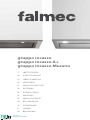 1
1
-
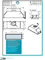 2
2
-
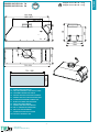 3
3
-
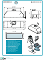 4
4
-
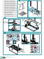 5
5
-
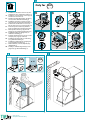 6
6
-
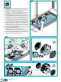 7
7
-
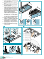 8
8
-
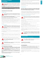 9
9
-
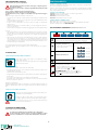 10
10
-
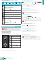 11
11
-
 12
12
-
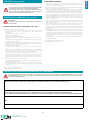 13
13
-
 14
14
-
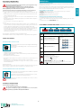 15
15
-
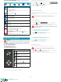 16
16
-
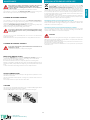 17
17
-
 18
18
-
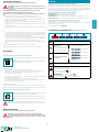 19
19
-
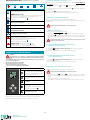 20
20
-
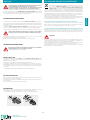 21
21
-
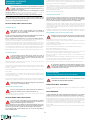 22
22
-
 23
23
-
 24
24
-
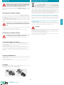 25
25
-
 26
26
-
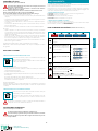 27
27
-
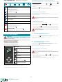 28
28
-
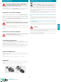 29
29
-
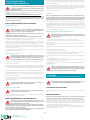 30
30
-
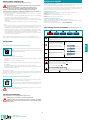 31
31
-
 32
32
-
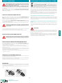 33
33
-
 34
34
-
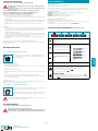 35
35
-
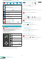 36
36
-
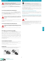 37
37
-
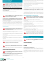 38
38
-
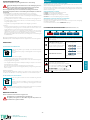 39
39
-
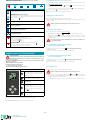 40
40
-
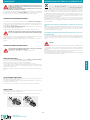 41
41
-
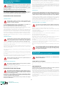 42
42
-
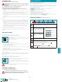 43
43
-
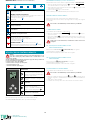 44
44
-
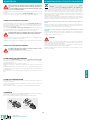 45
45
-
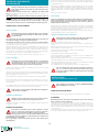 46
46
-
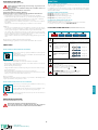 47
47
-
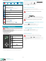 48
48
-
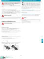 49
49
-
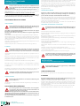 50
50
-
 51
51
-
 52
52
-
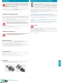 53
53
-
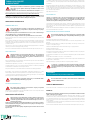 54
54
-
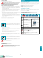 55
55
-
 56
56
-
 57
57
-
 58
58
-
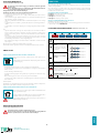 59
59
-
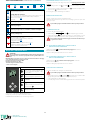 60
60
-
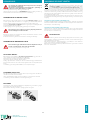 61
61
-
 62
62
-
 63
63
-
 64
64


Falmec Gruppo Incasso Kitchen Hood Benutzerhandbuch
- Typ
- Benutzerhandbuch
in anderen Sprachen
- English: Falmec Gruppo Incasso Kitchen Hood User manual
- français: Falmec Gruppo Incasso Kitchen Hood Manuel utilisateur
- español: Falmec Gruppo Incasso Kitchen Hood Manual de usuario
- italiano: Falmec Gruppo Incasso Kitchen Hood Manuale utente
- Nederlands: Falmec Gruppo Incasso Kitchen Hood Handleiding
- português: Falmec Gruppo Incasso Kitchen Hood Manual do usuário
- dansk: Falmec Gruppo Incasso Kitchen Hood Brugermanual
- svenska: Falmec Gruppo Incasso Kitchen Hood Användarmanual
Verwandte Artikel
-
Falmec FFLUX36W5SS Bedienungsanleitung
-
-
Falmec FDPST30I5SGW Bedienungsanleitung
-
-
-
-
Falmec FDMOV24W5SW Bedienungsanleitung
-