WIKA CPH6200 tag:model:CPT6200 Bedienungsanleitung
- Kategorie
- Messung
- Typ
- Bedienungsanleitung

Operating instructions
Betriebsanleitung
EN
DE
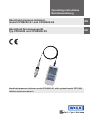
Hand-held pressure indicator model CPH6200-S1 with optional model CPT6200
reference pressure sensor
Hand-held pressure indicator,
model CPH6200-S1 and CPH6200-S2
Hand-Held Druckmessgerät,
Typ CPH6200 und CPH6200-S2

2
11221780.02 04/2019 EN/DE
WIKA operating instructions, model CPH6200
EN
DE
Operating instructions
model CPH6200-S1 and CPH6200-S2 Page 3 - 48
Betriebsanleitung
Typ CPH6200-S1 und CPH6200-S2 Seite 49 - 94
Further languages can be found at www.wika.com.
© 04/2019 WIKA Alexander Wiegand SE & Co. KG
All rights reserved. / Alle Rechte vorbehalten.
WIKA
®
is a registered trademark in various countries.
WIKA
®
ist eine geschützte Marke in verschiedenen Ländern.
Prior to starting any work, read the operating instructions!
Keep for later use!
Vor Beginn aller Arbeiten Betriebsanleitung lesen!
Zum späteren Gebrauch aufbewahren!

3WIKA operating instructions, model CPH6200
EN
11221780.02 04/2019 EN/DE
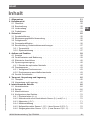
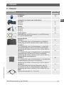
Contents
1. General information 5
2. Short overview 6
2.1 Overview . . . . . . . . . . . . . . . . . . . . . . . . 6
2.2 Description . . . . . . . . . . . . . . . . . . . . . . . 6
2.3 Scope of delivery . . . . . . . . . . . . . . . . . . . . . 7
2.4 Product passport . . . . . . . . . . . . . . . . . . . . . 7
3. Safety 9
3.1 Explanation of symbols . . . . . . . . . . . . . . . . . . . 9
3.2 Intended use. . . . . . . . . . . . . . . . . . . . . . . 9
3.3 Improper use . . . . . . . . . . . . . . . . . . . . . . 10
3.4 Personnel qualification . . . . . . . . . . . . . . . . . . . 10
3.5 Labelling, safety marks . . . . . . . . . . . . . . . . . . . 11
3.5.1 Product label . . . . . . . . . . . . . . . . . . . . . . . . . . . . . . . . . .11
3.5.2 Explanation of symbols. . . . . . . . . . . . . . . . . . . . . . . . . . . . .11
4. Design and function 12
4.1 Display. . . . . . . . . . . . . . . . . . . . . . . . . 12
4.2 Function buttons and operation . . . . . . . . . . . . . . . . 13
4.3 Electrical connections . . . . . . . . . . . . . . . . . . . 14
4.4 Voltage supply . . . . . . . . . . . . . . . . . . . . . . 16
4.4.1 Using the optional power supply unit . . . . . . . . . . . . . . . . . . . . .16
4.5 Pressure sensors . . . . . . . . . . . . . . . . . . . . . 17
4.5.1 Available pressure sensors . . . . . . . . . . . . . . . . . . . . . . . . . .17
4.5.2 Connecting/changing pressure sensors . . . . . . . . . . . . . . . . . . .17
4.6 Serial interface . . . . . . . . . . . . . . . . . . . . . .18
5. Transport, packaging and storage 19
5.1 Transport . . . . . . . . . . . . . . . . . . . . . . . .19
5.2 Packaging and storage . . . . . . . . . . . . . . . . . . . 19
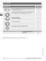
6. Commissioning, operation 20
6.1 Commissioning . . . . . . . . . . . . . . . . . . . . . .20
6.2 Operation . . . . . . . . . . . . . . . . . . . . . . . . 20
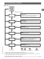
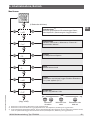
6.3 Menu functions . . . . . . . . . . . . . . . . . . . . . .21
6.4 Configuring the instrument . . . . . . . . . . . . . . . . . .24
6.4.1 Pressure units (unit). . . . . . . . . . . . . . . . . . . . . . . . . . . . . .24
6.4.2 Sea-level (SL) and altitude (Alti) correction for absolute pressure sensor 24
6.4.3 Measurement types (rAtE). . . . . . . . . . . . . . . . . . . . . . . . . . .25
6.4.4 Averaging . . . . . . . . . . . . . . . . . . . . . . . . . . . . . . . . . . . .26
6.4.5 Zero point correction sensor 1 (OFS.1) or sensor 2 (OFS.2) . . . . . . . . .26
6.4.6 Scale correction sensor 1 (SCL.1) and sensor 2 (SCL.2) . . . . . . . . . . .26
Contents

4 WIKA operating instructions, model CPH6200
EN
11221780.02 04/2019 EN/DE
Declarations of conformity can be found online at www.wika.com.
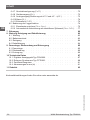
6.4.7 Power-off delay (P.oFF). . . . . . . . . . . . . . . . . . . . . . . . . . . . .27
6.4.8 Instrument output (Ovt). . . . . . . . . . . . . . . . . . . . . . . . . . . . .27
6.4.9 Analogue output scaling with dAC.0 and dAC.1 (dAC.) . . . . . . . . . . . .27
6.4.10 Alarm (AL.). . . . . . . . . . . . . . . . . . . . . . . . . . . . . . . . . . . .28
6.4.11 Real-time clock (CLOC) . . . . . . . . . . . . . . . . . . . . . . . . . . . . .28
6.5 Operation of the logger function . . . . . . . . . . . . . . . . 28
6.5.1 Storing individual values (Func-Stor). . . . . . . . . . . . . . . . . . . . .29
6.5.2 Automatic recording with adjustable cycle time (Func-CYCL) . . . . . . . .31
7. Faults 34
8. Maintenance, cleaning and recalibration 37
8.1 Maintenance. . . . . . . . . . . . . . . . . . . . . . . 37
8.2 Battery replacement . . . . . . . . . . . . . . . . . . . . 37
8.3 Cleaning . . . . . . . . . . . . . . . . . . . . . . . . 38
8.4 Recalibration. . . . . . . . . . . . . . . . . . . . . . . 38
9. Dismounting, return and disposal 39
9.1 Dismounting . . . . . . . . . . . . . . . . . . . . . . .39
9.2 Return . . . . . . . . . . . . . . . . . . . . . . . . .40
9.3 Disposal . . . . . . . . . . . . . . . . . . . . . . . . 40
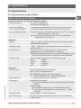
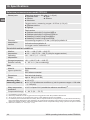
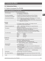
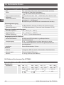
10. Specifications 41
10.1 Digital indicator model CPH6200 . . . . . . . . . . . . . . . 41
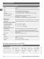
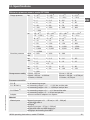
10.2 Reference pressure sensor model CPT6200 . . . . . . . . . . . 42
10.3 Certificates . . . . . . . . . . . . . . . . . . . . . . . 45
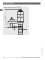
10.4 Dimensions in mm (in) . . . . . . . . . . . . . . . . . . .45
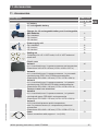
11. Accessories 47
Contents

5WIKA operating instructions, model CPH6200
EN
11221780.02 04/2019 EN/DE
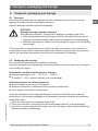
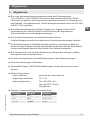
1. General information
1. General information
■
The model CPH6200-S1 or CPH6200-S2 hand-held pressure indicator described in
the operating instructions has been designed and manufactured using state-of-the-art
technology. All components are subject to stringent quality and environmental criteria
during production. Our management systems are certified to ISO 9001 and ISO 14001.
■
These operating instructions contain important information on handling the instrument.
Working safely requires that all safety instructions and work instructions are observed.
■
Observe the relevant local accident prevention regulations and general safety
regulations for the instrument's range of use.
■
The operating instructions are part of the product and must be kept in the immediate
vicinity of the instrument and readily accessible to skilled personnel at any time. Pass
the operating instructions on to the next operator or owner of the instrument.
■
Skilled personnel must have carefully read and understood the operating instructions
prior to beginning any work.
■
The general terms and conditions contained in the sales documentation shall apply.
■
Subject to technical modifications.
■
Factory calibrations / DKD/DAkkS calibrations are carried out in accordance with
international standards.
■
Further information:
- Internet address: www.wika.de / www.wika.com
- Relevant data sheet: CT 11.01
- Application consultant: Tel.: +49 9372 132-0
Fax: +49 9372 132-406
info@wika.de
■
Information on the firmware release and issue number of the operating instructions
Instructions Release Firmware
V 1.1 2001 V 4.0 - V 4.9
V 1.2 2003 V 5.0 - V 6.0
> V 1.3 11/2006 > V 6.0

6 WIKA operating instructions, model CPH6200
EN
11221780.02 04/2019 EN/DE
2. Short overview
2. Short overview
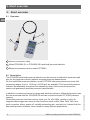
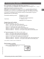
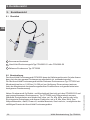
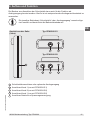
2.1 Overview
1
Sensor connection cable
2
Model CPH6200-S1 or CPH6200-S2 hand-held pressure indicator
3
Reference pressure sensor model CPT6200
2.2 Description
The CPH6200 hand-held pressure indicator can be used as a calibration instrument and
also for any application which requires accurate pressure measurement.
For the hand-held pressure indicator, model CPT6200 reference pressure sensors with
measuring ranges of up to 1,000 bar (14,500 psi) are available. This hand-held pressure
indicator automatically recognises the measuring range of the connected pressure
sensor and guarantees accurate pressure measurement.
In addition to pressure sensors for gauge and absolute pressure, differential pressure can
also be measured with the CPH6200-S2 and two connected model CPT6200 pressure
sensors.
Selectable pressure units here are bar, mbar, psi, Pa, kPa, MPa, mmHg or inHg. An
integrated data logger and various other functions (such as Min, Max, Hold, Tare, zero
point correction, alarm, power-off, variable measuring rate, sea level etc.) ensure that the
hand-held pressure indicator can be used for many different applications.
1
2
3

7WIKA operating instructions, model CPH6200
EN
11221780.02 04/2019 EN/DE
2. Short overview
2.3 Scope of delivery
■
Model CPH6200-S1 or CPH6200-S2 hand-held pressure indicator
■
9 V battery
■
One sensor connection cable per channel, approx. 1.1 m (3.3 ft)
■
Calibration certificate for sensor
■
Choice of sensors
Cross-check scope of delivery with delivery note.
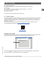
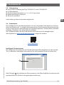
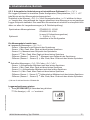
2.4 Product passport
The product passport is a web application where various information about an instrument
can be retrieved by entering the 11-digit alphanumeric serial number. This includes, for
example, instrument configuration, article number, operating instructions, data sheet or
calibration certificates.
The product passport can be retrieved from the product page or directly from the
corresponding web application (https://portal.wika.com/serial/).
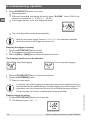
Web application
Intelligent serial number
The intelligent serial number and the corresponding web application is the central tool in
which all the required information on the specific instrument can be found.
After entering
1
the intelligent serial number into the web application, all instrument-
specific details on the manufactured version are displayed.
1

8 WIKA operating instructions, model CPH6200
EN
11221780.02 04/2019 EN/DE
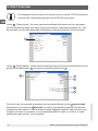
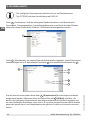
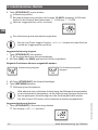
The intelligent serial number can only be found on model CPT6200 pressure
sensors with a manufacturing date from 03/2019 and younger.
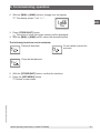
Under
2
“Product pass”, the most important additional information on the instrument,
such as measuring range, accuracy, process connection, manufacturing date, etc., can
be retrieved. You can also download (calibration) certificates directly from this location.
Under
3
“Article details”, further article details are listed, as well as documentation such
as the current data sheet
6
and current operating instructions
7
.
From this view, the required information can be printed directly via the
4
[print view].
Furthermore, by clicking on
5
[e-mail], an mail is opened which already contains the
intelligent serial number of the currently retrieved instrument and this can be sent to any
recipient, but also, for example, to a corresponding WIKA contact, in order to re-order
exactly the same product, as an example.
2
3
4
6
5
7
2. Short overview

9WIKA operating instructions, model CPH6200
EN
11221780.02 04/2019 EN/DE
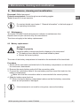
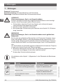
3. Safety
3. Safety
3.1 Explanation of symbols
WARNING!
... indicates a potentially dangerous situation that can result in serious injury
or death, if not avoided.
CAUTION!
... indicates a potentially dangerous situation that can result in light injuries or
damage to property or the environment, if not avoided.
DANGER!
... identifies hazards caused by electrical power. Should the safety
instructions not be observed, there is a risk of serious or fatal injury.
Information
... points out useful tips, recommendations and information for efficient and
trouble-free operation.
3.2 Intended use
The CPH6200 hand-held pressure indicator can be used as a calibration instrument and
also for any application which requires accurate pressure measurement.
This instrument is not permitted to be used in hazardous areas!
The instrument has been designed and built solely for the intended use described here,
and may only be used accordingly.
The technical specifications contained in these operating instructions must be observed.
Improper handling or operation of the instrument outside of its technical specifications
requires the instrument to be taken out of service immediately and inspected by an
authorised WIKA service engineer.
Handle electronic precision measuring instruments with the required care (protect from
humidity, impacts, strong magnetic fields, static electricity and extreme temperatures,
do not insert any objects into the instrument or its openings). Plugs and sockets must be
protected from contamination.
The manufacturer shall not be liable for claims of any type based on operation contrary to
the intended use.

10 WIKA operating instructions, model CPH6200
EN
11221780.02 04/2019 EN/DE
3. Safety
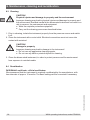
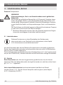
3.3 Improper use
WARNING!
Injuries through improper use
Improper use of the instrument can lead to hazardous situations and injuries.
▶
Refrain from unauthorised modifications to the instrument.
▶
Do not use the instrument within hazardous areas.
▶
Do not use the instrument with abrasive or viscous media.
▶
Observe the operating parameters in accordance with chapter
10 “Specifications”.
▶
Always operate the instrument within its overload limits.
Any use beyond or different to the intended use is considered as improper use.
3.4 Personnel qualification
WARNING!
Risk of injury should qualification be insufficient
Improper handling can result in considerable injury and damage to
equipment.
▶
The activities described in these operating instructions may only be
carried out by skilled personnel who have the qualifications described
below.
Skilled personnel
Skilled personnel, authorised by the operator, are understood to be personnel who,
based on their technical training, knowledge of measurement and control technology and
on their experience and knowledge of country-specific regulations, current standards and
directives, are capable of carrying out the work described and independently recognising
potential hazards.
Special operating conditions require further appropriate knowledge, e.g. of aggressive
media.

11WIKA operating instructions, model CPH6200
EN
11221780.02 04/2019 EN/DE
3. Safety
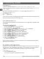
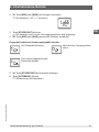
3.5 Labelling, safety marks
3.5.1 Product label
The operator is obliged to maintain the product label in a legible condition.
Product label for the hand-held pressure indicator (example)
The product label is fixed on the rear of the hand-held.
Product label for pressure sensor (example)
1
Product name
2
Article number
3
Date of manufacture (month-year)
4
Serial number
5
Barcode forwarding to Web application
6
Pressure measuring range and accuracy
3.5.2 Explanation of symbols
Before mounting and commissioning the hand-held pressure indicator,
ensure you read the operating instructions!
Do not dispose of with household waste. Ensure a proper disposal in
accordance with national regulations.
Kalibriertechnik / Calibration Technology
1
2
3
4
1
6
4
2
5
3

12 WIKA operating instructions, model CPH6200
EN
11221780.02 04/2019 EN/DE
4. Design and function
4. Design and function
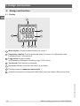
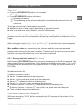
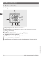
4.1 Display
1
Main display: Current measured value for sensor 1
2
Secondary display: Current measured value for sensor 2 or differential value
between sensor 1 and sensor 2
3
Logg arrow: Logger is ready
Arrow blinking: Automatic recording (Logg CYCL) active
4
Tare arrow: Tare function is activated
5
SL arrow: Altitude correction (sea level) is activated
6
Display arrows for measured value units
7
Indication elements for showing the Min./Max. measured value, difference or hold
6
6
7
1
2
45 3

13WIKA operating instructions, model CPH6200
EN
11221780.02 04/2019 EN/DE
4. Design and function
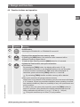
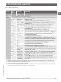
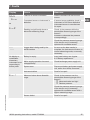
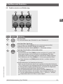
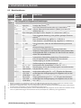
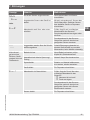
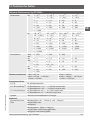
4.2 Function buttons and operation
Pos. Symbol Meaning
7
ON
OFF
On/Off button
Switching the CPH6200-S1 or CPH6200-S2 on and off
8
▲
MAX
Display of the respective max. memory value
By pressing the [MAX] button, the maximum value measured will be
displayed. Pressing it again hides it.
To clear the Max. memory, press the [MAX] button for > 2 seconds.
9
▲
TA R A
Activate the Tare function, zero point correction
■
Tare function
By pressing the [TARA] button, the display will be set to “0”. All
measurements from then on are displayed relative to the set Tare value.
If the tare function is activated, the 'Tare' arrow will be displayed. To
deactivate, press and hold the [TARA] button for > 2 seconds.
⇒
By activating [TARA] the Min. and Max. memory will be deleted.
■
Zero point correction (for gauge pressure sensors)
When there is no pressure on the pressure ports, the instrument will display
a “0”. However, if there is a permanent deviation (when operating in trouble-
free ambient conditions), there is a possibility to carry out a permanent zero
point correction.
In order to carry out a zero point correction, press the [TARA] button for
approx. 5 seconds. (Only possible if the display value deviates from the
factory calibration by less than 2 %, e.g. 0 ... 25 bar (0 ... 360 psi)
⇒
Zero point correction up to 0.5 bar (7.3 psi) possible.
7
12
8
11
9
10

14 WIKA operating instructions, model CPH6200
EN
11221780.02 04/2019 EN/DE
4. Design and function
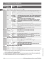
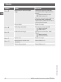
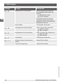
Pos. Symbol Meaning
⇒
The adjustment can only be carried out if the deviation is less than 500
digits. If a zero point correction has been made, this will be signalled
by the message 'nuLL-Corr' being displayed briefly as the instrument is
switched on.
■
Restoring the factory calibration
By pressing the [TARA] button for approx. 15 seconds, the factory settings
will be restored.
10
QUIT
STORE
Activate hold function or logger function
(See chapter 6.5 “Operation of the logger function”)
■
Hold function
By pressing the [STORE/QUIT] button, the last measured value will be
shown in the lower display. Pressing it again hides the value again (only
when logger is deactivated).
■
Logger function
Activated by the [STORE/QUIT] button, only if the logger function has
been selected via the main menu (see chapter 6.5 “Operation of the logger
function”).
11
▲
MIN
Display the respective Min. memory
By pressing the [MIN] button, the minimum value measured will be displayed.
Pressing it again hides it.
To clear the Min. memory, press the [MIN] button for > 2 seconds.
12
MENU
SET
Enter configuration
By pressing the [SET/MENU] button for approx. 2 seconds, the settings
such as configuration, adjustment, alarm logger and system clock can be
accessed.
■
Differentiation
By pressing the [SET/MENU] button, the lower display will show the
difference of channel 1 to channel 2 (DIF = CH1 - CH2). Pressing it again
undoes this action. (Only with 2-channel version and 2 connected pressure
sensors).
Abbreviations, definitions
“XXX” Menu XXX will be selected
[XXX] Press button XXX
‚XXX‘ Display of a message 'XXX'
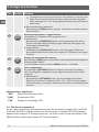
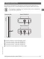
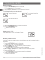
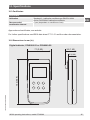
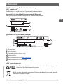
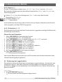
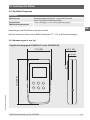
4.3 Electrical connections
On the upper edge of the instrument are located the connection sockets CH1 and CH2
(CH2 only with the 2-channel version) for the connection of model CPT6200 pressure
sensors (see chapter 4.5 “Pressure sensors”), as is the socket for the connection of the
WIKA interface cable (see chapter 4.6 “Serial interface”).

15WIKA operating instructions, model CPH6200
EN
11221780.02 04/2019 EN/DE
4. Design and function
The sockets for the connection of the interface can also be used for the function of
analogue output. For this, a corresponding analogue connection cable must be used.
The “interface” or “analogue output” operating mode must be configured via
menu and affects battery life!
1
Interface connector or optional analogue output
2
Connection channel 1 (only with CPH6200-S1)
3
Connection channel 2 (only with CPH6200-S2)
4
Connection channel 1 (only with CPH6200-S2)
5
Connection of power supply unit for voltage supply
Side view (left)
5
12
134
Model CPH6200-S1
Model CPH6200-S2

16 WIKA operating instructions, model CPH6200
EN
11221780.02 04/2019 EN/DE
4.4 Voltage supply
The voltage supply of the instrument is made via a 9 V battery. This is included in the
scope of delivery. Alternatively, a 9 V rechargeable battery can be used which can be
charged using a charging unit for 9 V rechargeable batteries.
The battery life is approx. 300 hours of continuous operation with one sensor and a
measuring rate of 4/s.
The battery indicator lights up
To avoid false readings, replace the batteries.
If “bAt” is displayed in the lower display, the battery has been run down
and must be replaced or the rechargeable battery is empty and must be
charged with a suitable charging unit. However, the instrument function is
still ensured for a certain time.
If “bAt” is displayed in the upper display, the battery has been completely
run down or the rechargeable battery is empty.
If the instrument is not used for a long time, the battery/rechargeable battery
should be removed.
The real-time clock has to be set again once the battery has been
reconnected.
The battery and rechargeable battery must only be used in a proper fashion
and must be disposed of properly in line with the current, national regulations.
When storing the instrument at over 50 °C (122 °F), the battery/rechargeable
battery must be taken out.
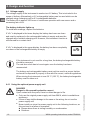
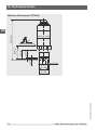
4.4.1 Using the optional power supply unit
DANGER!
Danger to life caused by electric current
Upon contact with live parts, there is a direct danger to life.
▶
Only use the original power supply unit from WIKA, which is available as
accessory.
▶
If there is any visible damage to the case or the wiring, do not use the
power supply unit!
▶
Never install nor store the power supply unit in the following locations, as
this can lead to a failure in operation:
■
Places where there is strong humidity or condensation
■
Outdoors
4. Design and function

17WIKA operating instructions, model CPH6200
EN
11221780.02 04/2019 EN/DE
▶
Disconnect the power supply unit from the mains supply when it won't be
used for a longer period of time.
▶
The power supply unit is maintenance-free. It must not be opened (danger
of electrical shock).
▶
Before cleaning, disconnect the power supply unit from the mains supply.
Do not clean with chemical cleaning agents. Only clean with a dry cloth.
The power supply unit enables a permanent power supply for the CPH6200
without using a 9 V battery or a 9 V rechargeable battery.
The power supply unit is not suitable for recharging the 9 V rechargeable
battery. The charging of the 9 V rechargeable battery must only be made
using an external charging unit.
4.5 Pressure sensors
CAUTION!
Damage to the instrument
If third-party reference pressure sensors are used, they can damage the
hand-held pressure indicator and the reference pressure sensor.
▶
Only use model CPT6200 reference pressure sensors!
▶
Only ever use the original connection cable from WIKA for the operation of
CPT6200 reference pressure sensors.
4.5.1 Available pressure sensors
The hand-held has been designed so that all model CPT6200 pressure sensors can
be connected without the need for any readjustment. A wide range of interchangeable
sensors is therefore available, with ranges of up to 1,000 bar (14,500 psi), see chapter
10 “Specifications”.
4.5.2 Connecting/changing pressure sensors
CAUTION!
Damage to the instrument
For overpressure or gauge sensors, the pressure compensation vent hole is
found at the top of the sensor housing.
▶
This vent (with integrated diaphragm) must always remain clear!
Before switching the instrument on, connect the reference pressure sensor,
otherwise it may not be correctly identified by the instrument.
4. Design and function

18 WIKA operating instructions, model CPH6200
EN
11221780.02 04/2019 EN/DE
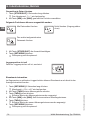
1. To connect or change the reference pressure sensor, switch off the instrument.
2. Connect the hand-held pressure indicator and the pressure sensor to each other
electrically using a separate sensor connection cable. Use the 7-pin plug contact on
the pressure sensor for this.
3. Connect the 7-pin connector to the reference pressure sensor in accordance with the
orientation guide and secure it through the connection sleeve.
Turn the connection sleeve clockwise without much force.
4. Connect the 6-pin M-DIN connector to the hand-held on CH1 or CH2 in accordance
with the orientation guide.
When connecting the sensor connection cable to the hand-held, the pressure sensor's
connector might not locate properly in the socket. In this event you should try holding the
connector by the bend protection, rather than by the connector sleeve.
▶
Connect the connector without tilting the threads.
⇒
If the connector is positioned correctly, it can be plugged in without any significant
effort.
▶
When removing the pressure sensor, do not pull on the sensor connection cable, but
only on the connector sleeve.
4.6 Serial interface
For the data transfer to a computer, only use the interface cable from WIKA. These are
suitable for connection to a USB interface (USB driver needed) or an RS-232 interface.
The USB interface cable consists of a USB connector (model A) at one end of the cable
and a 3.5 mm stereo jack connector at the other end of the cable.
The cable is approx. 2 m (6.6 ft) long.
The RS-232 interface cable consists of a 9-pin Sub-D female connector at one end of the
cable and a 3.5 mm stereo jack connector at the other end of the cable.
The cable is approx. 1.5 m (4.9 ft) long.
4. Design and function

19WIKA operating instructions, model CPH6200
EN
11221780.02 04/2019 EN/DE
5. Transport, packaging and storage
5. Transport, packaging and storage
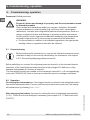
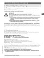
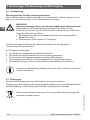
5.1 Transport
Check the hand-held pressure indicator and the reference pressure sensor for any
damage that may have been caused by transport.
Obvious damage must be reported immediately.
CAUTION!
Damage through improper transport
With improper transport, a high level of damage to property can occur.
▶
When unloading packed goods upon delivery as well as during internal
transport, proceed carefully and observe the symbols on the packaging.
▶
With internal transport, observe the instructions in chapter 5.2 “Packaging
and storage”.
If the instrument is transported from a cold into a warm environment, the formation of
condensation may result in instrument malfunction. Before putting it back into operation,
wait for the instrument temperature and the room temperature to equalise.
5.2 Packaging and storage
Do not remove packaging until just before mounting.
Keep the packaging as it will provide optimum protection during transport (e.g. change in
use, sending for repair).
Permissible conditions at the place of storage:
■
Storage temperature: -20 ... +70 °C (-4 ... +158 °F)
■
Humidity: 0 ... 95 % relative humidity (non-condensing)
Avoid exposure to the following factors:
■
Direct sunlight or proximity to hot objects
■
Mechanical vibration, mechanical shock (putting it down hard)
■
Soot, vapour, dust and corrosive gases
Store the instrument in its original packaging in a location that fulfils the conditions
listed above. If the original packaging is not available, pack and store the instrument as
described below:
1. Wrap the instrument in an antistatic plastic film.
2. Place the instrument, along with the shock-absorbent material, in the packaging.
3. If stored for a prolonged period of time (more than 30 days), place a bag containing a
desiccant inside the packaging.

20 WIKA operating instructions, model CPH6200
EN
11221780.02 04/2019 EN/DE
6. Commissioning, operation
6. Commissioning, operation
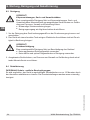
Personnel: Skilled personnel
WARNING!
Physical injuries and damage to property and the environment caused
by hazardous media
Upon contact with hazardous media (e.g. oxygen, acetylene, flammable
or toxic substances), harmful media (e.g. corrosive, toxic, carcinogenic,
radioactive), and also with refrigeration plants and compressors, there is a
danger of physical injuries and damage to property and the environment.
Should a failure occur, aggressive media with extremely high temperature
and under high pressure or vacuum may be present at the instrument.
▶
For these media, in addition to all standard regulations, the appropriate
existing codes or regulations must also be followed.
6.1 Commissioning
Before switching the instrument on, connect the reference pressure sensor,
otherwise it may not be correctly identified by the instrument, see chapter
4.5.2 “Connecting/changing pressure sensors”.
Before switching on, connect the reference pressure sensor(s) to the intended female
connector of the hand-held and make sure that a fully charged 9 V battery or a fully
charged rechargeable 9 V battery is inserted.
The connection sockets are marked on the instrument case with 1 or 2 correspondingly
(only with CPH6200-S2). Next to these are located the serial or analogue interfaces.
6.2 Operation
On turning the instrument on, if the logger function is selected, the integrated clock‘s
time will be displayed briefly. If a zero point correction has been carried out, the display
will indicate this by showing “nuLL-Corr”.
After changing the battery the menu for setting the clock is displayed automatically
(‘CLOC’). Check the clock and adjust if necessary (see chapter 6.4.11 “Real-time clock
(CLOC)”).
Seite wird geladen ...
Seite wird geladen ...
Seite wird geladen ...
Seite wird geladen ...
Seite wird geladen ...
Seite wird geladen ...
Seite wird geladen ...
Seite wird geladen ...
Seite wird geladen ...
Seite wird geladen ...
Seite wird geladen ...
Seite wird geladen ...
Seite wird geladen ...
Seite wird geladen ...
Seite wird geladen ...
Seite wird geladen ...
Seite wird geladen ...
Seite wird geladen ...
Seite wird geladen ...
Seite wird geladen ...
Seite wird geladen ...
Seite wird geladen ...
Seite wird geladen ...
Seite wird geladen ...
Seite wird geladen ...
Seite wird geladen ...
Seite wird geladen ...
Seite wird geladen ...
Seite wird geladen ...
Seite wird geladen ...
Seite wird geladen ...
Seite wird geladen ...
Seite wird geladen ...
Seite wird geladen ...
Seite wird geladen ...
Seite wird geladen ...
Seite wird geladen ...
Seite wird geladen ...
Seite wird geladen ...
Seite wird geladen ...
Seite wird geladen ...
Seite wird geladen ...
Seite wird geladen ...
Seite wird geladen ...
Seite wird geladen ...
Seite wird geladen ...
Seite wird geladen ...
Seite wird geladen ...
Seite wird geladen ...
Seite wird geladen ...
Seite wird geladen ...
Seite wird geladen ...
Seite wird geladen ...
Seite wird geladen ...
Seite wird geladen ...
Seite wird geladen ...
Seite wird geladen ...
Seite wird geladen ...
Seite wird geladen ...
Seite wird geladen ...
Seite wird geladen ...
Seite wird geladen ...
Seite wird geladen ...
Seite wird geladen ...
Seite wird geladen ...
Seite wird geladen ...
Seite wird geladen ...
Seite wird geladen ...
Seite wird geladen ...
Seite wird geladen ...
Seite wird geladen ...
Seite wird geladen ...
Seite wird geladen ...
Seite wird geladen ...
Seite wird geladen ...
Seite wird geladen ...
-
 1
1
-
 2
2
-
 3
3
-
 4
4
-
 5
5
-
 6
6
-
 7
7
-
 8
8
-
 9
9
-
 10
10
-
 11
11
-
 12
12
-
 13
13
-
 14
14
-
 15
15
-
 16
16
-
 17
17
-
 18
18
-
 19
19
-
 20
20
-
 21
21
-
 22
22
-
 23
23
-
 24
24
-
 25
25
-
 26
26
-
 27
27
-
 28
28
-
 29
29
-
 30
30
-
 31
31
-
 32
32
-
 33
33
-
 34
34
-
 35
35
-
 36
36
-
 37
37
-
 38
38
-
 39
39
-
 40
40
-
 41
41
-
 42
42
-
 43
43
-
 44
44
-
 45
45
-
 46
46
-
 47
47
-
 48
48
-
 49
49
-
 50
50
-
 51
51
-
 52
52
-
 53
53
-
 54
54
-
 55
55
-
 56
56
-
 57
57
-
 58
58
-
 59
59
-
 60
60
-
 61
61
-
 62
62
-
 63
63
-
 64
64
-
 65
65
-
 66
66
-
 67
67
-
 68
68
-
 69
69
-
 70
70
-
 71
71
-
 72
72
-
 73
73
-
 74
74
-
 75
75
-
 76
76
-
 77
77
-
 78
78
-
 79
79
-
 80
80
-
 81
81
-
 82
82
-
 83
83
-
 84
84
-
 85
85
-
 86
86
-
 87
87
-
 88
88
-
 89
89
-
 90
90
-
 91
91
-
 92
92
-
 93
93
-
 94
94
-
 95
95
-
 96
96


WIKA CPH6200 tag:model:CPT6200 Bedienungsanleitung
- Kategorie
- Messung
- Typ
- Bedienungsanleitung
in anderen Sprachen
Verwandte Artikel
-
WIKA CPT62I0 Bedienungsanleitung
-
-
-
-
-
-
-
-
-
Andere Dokumente
-
Omega GMH3750 Bedienungsanleitung
-
 Tecsis E3905 Bedienungsanleitung
-
Laserliner SoundTest-Master Bedienungsanleitung
-
Dostmann GD 383 Gas-Lecksuchgerät Benutzerhandbuch
-
-
Ahlborn ALMEMO 202 Bedienungsanleitung
-
-
-
ABB TZIDC-110 Commissioning Instructions
-
 Hach AV9000 Benutzerhandbuch

