
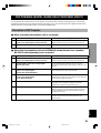
YAMAHA ELECTRONICS CORPORATION, USA 6660 ORANGETHORPE AVE., BUENA PARK, CALIF. 90620, U.S.A.
YAMAHA CANADA MUSIC LTD. 135 MILNER AVE., SCARBOROUGH, ONTARIO M1S 3R1, CANADA
YAMAHA ELECTRONIK EUROPA G.m.b.H. SIEMENSSTR. 22-34, 25462 RELLINGEN BEI HAMBURG, F.R. OF GERMANY
YAMAHA ELECTRONIQUE FRANCE S.A. RUE AMBROISE CROIZAT BP70 CROISSY-BEAUBOURG 77312 MARNE-LA-VALLEE CEDEX02, FRANCE
YAMAHA ELECTRONICS (UK) LTD. YAMAHA HOUSE, 200 RICKMANSWORTH ROAD WATFORD, HERTS WD1 7JS, ENGLAND
YAMAHA SCANDINAVIA A.B. J A WETTERGRENS GATA 1, BOX 30053, 400 43 VÄSTRA FRÖLUNDA, SWEDEN
YAMAHA MUSIC AUSTRALIA PTY, LTD. 17-33 MARKET ST., SOUTH MELBOURNE, 3205 VIC., AUSTRALIA
Printed in China ID V586140
OWNER’S MANUAL
MODE D’EMPLOI
BEDIENUNGSANLEITUNG
BRUKSANVISNING
MANUALE DI ISTRUZIONI
MANUAL DE INSTRUCCIONES
GEBRUIKSAANWIJZING
AV-S70
Home Theater Sound System
Systèm audio home cinéma
AV-S70
G B
00AV-S70-cv 3/29/0, 6:07 PM1

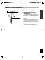
CAUTION
CAUTION: READ THIS BEFORE OPERATING YOUR UNIT.
1. To assure the finest performance, please read this
manual carefully. Keep it in a safe place for future
reference.
2. Install this unit in a cool, dry, clean place — away
from windows, heat sources, sources of excessive
vibration, dust, moisture and cold. Avoid sources of
humming (transformers, motors). To prevent fire or
electrical shock, do not expose the unit to rain or
water.
3. Never open the cabinet. If something drops into the
unit, contact your dealer.
4. Do not use force on switches, controls or connection
cables. When moving the unit, first disconnect the
power cord and then the cables connected to other
component. Never pull the cables themselves.
5. The openings on the cover assure proper ventilation
of the unit. If these openings are obstructed, the
temperature inside the unit will rise rapidly.
Therefore, avoid placing objects against these
openings, and install the unit in a well-ventilated area
to prevent fire and damage.
6. The voltage used must be the same as that specified
on this unit. Using this unit with a higher voltage than
specified is dangerous and may result in fire or other
accidents. YAMAHA will not be held responsible for
any damage resulting from the use of this unit with a
voltage other than that specified.
7. Digital signals generated by this unit may interfere
with other component such as tuners, receivers and
TVs. Move this unit farther away from such
component if interference is observed.
8. Always set the volume to the minimum level before
starting the audio source play. Increase the volume
gradually to an appropriate level after playback has
been started.
9. Do not attempt to clean the unit with chemical
solvents; this might damage the finish. Use a clean,
dry cloth.
10. Be sure to read the “TROUBLESHOOTING” section
regarding common operating errors before
concluding that the unit is faulty.
11. When not planning to use this unit for a long period
of time (e.g., a vacation), disconnect the AC power
cord from the wall outlet.
12. To prevent lightning damage, disconnect the AC
power cord and disconnect the antenna cable when
there is an electrical storm.
13. Grounding or polarization — Precautions should be
taken so that the grounding or polarization of the unit
is not defeated.
14. AC outlet — Do not connect audio component to the
AC outlet on the rear panel if that component
requires more power than the outlet is rated to
provide.
15. Though this speaker is a magnetic shielding type,
there may be some influence on a TV picture
depending on the type of TV or the placement of the
speaker. In such a case, place the speaker apart from
the TV so that there is no influence on TV picture.
This unit is not disconnected from the AC power source
as long as it is connected to the wall outlet, even if this
unit itself is turned off. This state is called the standby
mode. In this state, this unit is designed to consume a
very small quantity of power.
■ For U.K. customers
If the socket outlets in the home are not suitable for the plug
supplied with this appliance, it should be cut off and an
appropriate 3 pin plug fitted. For details, refer to the
instructions described below.
Note
• The plug severed from the mains lead must be destroyed, as a
plug with bared flexible cord is hazardous if engaged in a live
socket outlet.
■ Special Instructions for U.K. Model
IMPORTANT
THE WIRES IN MAINS LEAD ARE COLOURED IN
ACCORDANCE WITH THE FOLLOWING CODE:
Blue: NEUTRAL
Brown: LIVE
As the colours of the wires in the mains lead of this
apparatus may not correspond with the coloured
markings identifying the terminals in your plug, proceed
as follows:
The wire which is coloured BLUE must be connected to
the terminal which is marked with the letter N or
coloured BLACK. The wire which is coloured BROWN
must be connected to the terminal which is marked with
the letter L or coloured RED.
Making sure that neither core is connected to the earth
terminal of the three pin plug.
0101AV-S70_caution_EN 3/29/0, 12:47 PM2

1
EnglishREMOTE CONTROL APPENDIXPREPARATION
OPERATION
FEATURES
● Home Theater Sound
This system delivers a realistic and powerful sound
experience like that found in a movie theater just by
connecting the front speaker unit to the TV. You can
also enjoy stronger bass and surround effects by
adding the separately available YAMAHA NX-SW70,
consisting of a subwoofer and two rear speakers.
● Includes Dolby Digital* and Dolby Pro
Logic Decoder
This system can reproduce the sound field of the
software with the g or s logo
mark.
● Virtual Surround
The front speaker unit can produce a virtual Dolby
Surround sound field when playing software with the
g or s logo mark so that you can
enjoy surround effects that give motion to sound and
make you feel like you are inside the action.
● Seven DSP programs including
YAMAHA CINEMA DSP
Connecting the YAMAHA NX-SW70 (sold
separately) allows seven different DSP programs to be
used to enhance the power and realism of various
sources, from movies, to concerts, and sporting
events.
● Preset Remote Control
The remote control can be used to control not only the
front speaker unit, but component from other
manufacturers as well merely by setting the proper
manufacturer code.
y indicates a tip for your operation.
PREPARATION
Manufactured under license from Dolby
Laboratories. “Dolby”, “Pro Logic” and the
double-D symbol are trademarks of Dolby
Laboratories. Confidential Unpublished Works.
©1992 – 1997 Dolby Laboratories, Inc. All rights
reserved.
CONTENTS
OPERATION
OPERATING THE UNIT ......................................... 17
USING CONVENIENT FUNCTIONS .................... 18
DSP PROGRAM (DIGITAL SOUND FIELD
PROCESSOR EFFECT)........................................ 19
MENU FUNCTIONS................................................. 21
REMOTE CONTROL
OPERATING OTHER COMPONENTS USING
THE REMOTE CONTROL .................................. 23
APPENDIX
GLOSSARY................................................................ 28
TROUBLESHOOTING ............................................ 29
SPECIFICATIONS.................................................... 30
INDEX ........................................................................ 31
PREPARATION
FEATURES .................................................................. 1
GETTING STARTED ................................................. 2
NAMES OF ALL PARTS ............................................ 4
SPEAKER PLACEMENT .......................................... 6
INSTALLATION ......................................................... 7
CONNECTIONS.......................................................... 9
ADJUSTING THE SPEAKER
OUTPUT LEVELS ................................................. 15
0102AV-S70_01-08_EN 3/29/0, 12:49 PM1

2
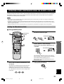
GETTING STARTED
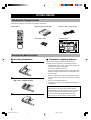
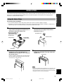
Checking the Package Contents
Check that the following accessories are included in the package.
Remote control Batteries (AAA, R03, UM-4 type) Audio connection cord (2 pin, 3m)
Velcro strips (2 sets) Connection guide
Readying the Remote Control
■ Inserting the batteries
1 Remove the battery compartment cover.
2 Insert the four batteries (AAA, R03, UM-4 type)
with + and – oriented properly.
3 Close the battery compartment cover.
■ Precautions regarding batteries
Misuse of dry cell batteries may result in leakage or
bursting. Be sure to follow the precautions given below.
• Insert batteries with (+) and (–) oriented according to the
marking in the battery compartment.
• Do not mix old and new batteries.
• Do not mix different types of batteries as they may offer
different voltage and performance even though they have
the same shape.
• Remove all batteries when they can no longer be used or
when the remote control will not be used for an extended
period.
• Do not use rechargeable batteries.
• If leakage occurs, wipe away all battery fluid inside the
compartment.
Preserving the manufacturer code
Replace batteries early before they become unusable.
The manufacturer code set by the user will be preserved
for about two minutes when batteries run out or when
they are removed. Note that the manufacturer code
setting may be lost if more than two minutes elapses.
0102AV-S70_01-08_EN 3/29/0, 12:49 PM2

3
EnglishREMOTE CONTROL APPENDIXPREPARATION OPERATION
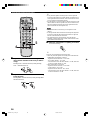
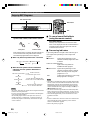
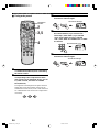
GETTING STARTED
Operational Area of the Remote Control
Front speaker
Approx. 20 cm – 6 m
30° 30°
■ Battery replacement cycle
Replace all four batteries when the operational range of the
remote control starts to become shorter.
■ Precautions on handling the
remote control
• The remote control may not be able to operate the front
speaker unit when an object blocks the remote control
sensor on the unit.
• Do not subject the remote control to impact. Do not
allow it to get wet or place it in a location subject to high
humidity.
• The remote control operations become difficult when
direct sunlight or other strong light (such as from an
inverter fluorescent lamp) strikes the sensor. Adjust the
relative positions of the light and the front speaker if this
happens.
• Remote control operations may not be possible if another
remote control is being operated at the same time.
0102AV-S70_01-08_EN 3/29/0, 12:49 PM3

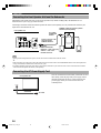
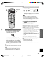
4
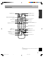
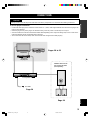
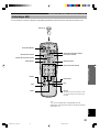
NAMES OF ALL PARTS
Front Speaker Unit (Front Panel)
INPUT selector button (page 17)
VOLUME +/– (page 17)
DSP selector button
(page 20)
STANDBY indicator
POWER (page 17)
Turns the unit’s power on and off. This
button also turns off the subwoofer’s
power when a YAMAHA subwoofer
and rear speakers NX-SW70 (sold
separately) are connected. The
STANDBY indicator will light when
power is turned off using p on the
remote control.
Display
VIRTUAL indicator (page 20) TRUBASS indicator (page 18) ENHANCED indicator
Processing indicators (page 20)
Display used for DSP program name, level,
and operational status
DSP
DIGITAL ENHANCED
SURROUND
PRO LOGIC
VIRTUAL TRUBASS
0102AV-S70_01-08_EN 3/29/0, 12:49 PM4

5
EnglishREMOTE CONTROL APPENDIXPREPARATION OPERATION
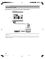
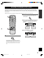
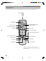
NAMES OF ALL PARTS
Remote Control
p (power) (page 17)
Remote control selector buttons
(page 23)
VOL – (page 17)
m (page 18)
SET/DSP (pages 20 and 23)
MENU – (page 21)
SUBWOOFER – (page 18)
NIGHT MODE (page 18)
t (page 18)
DSP ON/OFF (page 20)
Transmission indicator
Not used with this unit.
VOL + (page 17)
c (page 23)
INPUT selector button (page 17)
Numeric buttons (page 23)
SUBWOOFER + (page 18)
TEST (page 15)
Not used with this unit.
y
Of the buttons on the remote control, those used to control this unit
is colored in dark gray.
MENU + (page 21)
MENU (page 21)
0102AV-S70_01-08_EN 3/29/0, 12:49 PM5

6
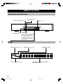
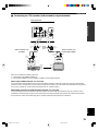
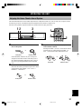
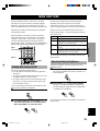
SPEAKER PLACEMENT
Although speakers should ideally be placed as shown below, satisfactory effects may be obtained even if you do not strictly
follow these guidelines.
■ Front speaker unit
Place the front speaker unit on top of the television and
align the front surface of the speakers with the front surface
of the television monitor. For details on placement, refer to
page 7. If the system cannot be placed on top of the
television, place it on a rack beneath the television as close
to the television monitor as possible.
■ YAMAHA rear speakers NX-AVS70
(sold separately)
Depending on room conditions, it is possible to place
YAMAHA rear speakers NX-AVS70 on shelves or hang
them on the wall. Speakers should be placed about 1.8 m
above the floor.
About 1.8 m
■ YAMAHA subwoofer SW-AVS70
(sold separately)
Place the subwoofer at the either right or left side of the
front speaker unit and facing slightly toward the center of
the room so that the sound from it and the sound reflected
by the wall should not cancel out each other. Try altering the
position of the subwoofer versus the listening position as the
relative position will affect the way the bass sounds.
CAUTION
Although the speakers in this unit are magnetically
shielded, they may still affect the color on the television
monitor when using the speakers on top of the television.
Adjust the relative positions of the speakers and the
television if this happen. Perform the following steps if
you are using a magnetically shielded television.
1 Turn off the television.
2 Wait awhile and turn the television back on.
Front speaker unit
Place above the monitor in the center.
Subwoofer (sold separately or already owned)
Left rear
speaker
Rear speakers (sold separately)
Place behind or to the sides of the listening position.
Right rear
speaker
1.8 m
0102AV-S70_01-08_EN 3/29/0, 12:49 PM6

7
EnglishREMOTE CONTROL APPENDIXPREPARATION OPERATION
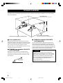
INSTALLATION
To prevent the front speaker unit from falling, secure it with the provided velcro strip when placing it on a television or other
device. Also, use the height adjustment bracket on the rear of the front speaker unit when there is not enough space for
installation or when the surface is sloped.
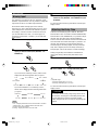
Using the Velcro Strips
Precautions before installation
• Do not touch the adhesive surface after peeling off the strip as this will weaken its adhesive strength.
• Thoroughly wipe clean the surface where the velcro strip is to be applied. Note that adhesive strength is weakened if the
surface is dusty, oily or wet and that this may cause the front speaker unit to drop.
1 Peel off the seal of the velcro strip with the
rough surface and apply to the protrusions on
the bottom of the front speaker unit.
Wrap the strip tightly with
sides of the tape well
aligned with the edges of
the protrusion.
Rough surface
Front speaker
(bottom panel)
Protrusion
2 Place the front speaker unit where it is to be
installed (ex. on top of the television ) to
determine where to apply the velcro strip with
the smooth surface.
Position so that the position of the velcro strip stuck to
the front speaker unit matches that of the velcro strip
stuck to the top of the television.
3 Peel off the seal of the velcro strip with the
smooth surface and apply to the positions
determined in step 2.
Peel off the seal.
Smooth surface
4 Align both the velcro strip on both sides and
firmly press downward on the top of the front
speaker unit.
Press down.
Note
• Once the front speaker unit is secured in this way, the paint on the
television surface used for installation may peel off when velcro
strip is removed later. Be sure to apply velcro strip after carefully
checking the surface to be used for installation.
0102AV-S70_01-08_EN 3/29/0, 12:49 PM7

8
INSTALLATION
Using the Height Adjustment Brackets
1 Loosen the screws securing the adjustment
bracket.
Loosen the screws.
2 Lower the bracket so that the front speaker
unit is level and securely tighten the screws.
Lower the
bracket and
adjust.
Securely tighten
the screws.
Place the front
speaker unit so that it
is level.
■ To further stabilize and prevent
falling
Wire attachment
hole
Secure the front speaker unit to the wall by attaching
sufficiently strong wire to the wire attachment hole on the
adjustment bracket. This prevents falling in two ways when
this method is used together with velcro strip. This can
prevent damage caused by the front speaker falling.
Note
• Please provide wire separately.
CAUTION
Never place anything on top of the front speaker unit.
0102AV-S70_01-08_EN 3/29/0, 12:49 PM8

9
EnglishREMOTE CONTROL APPENDIXPREPARATION OPERATION
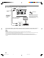
CONNECTIONS
CAUTION
Always be sure to turn off the power of the main unit and any component to be connected when making connections.
To ensure proper connections
• Connect the white plug of the connection cord to the left “L” (white) audio signal terminal and connect the red plug to the
right “R”(red) terminal.
• Insert the plug securely. If the plug is not inserted securely, noise may result or sound may not be output.
• Since the method of connection and terminal names differ depending on the component being used, be sure to refer to the
instruction manuals for all components being connected.
• After connections have been made, check one more time that wiring has been made properly.
Pages 10 to 12
TV (monitor) VCR, etc.
DVD player,
LD player, etc.
Front speaker unit
Page 14
AC outlet
YAMAHA subwoofer and
rear speakers NX-SW70
(sold separately)
Page 14
0103AV-S70_09-16_EN 3/29/0, 1:00 PM9

10
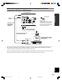
CONNECTIONS
Connecting a TV or VCR
■ Connecting a TV (monitor) with audio output terminals
Connect the audio output terminal on the TV (monitor) to the TV terminal on the front speaker unit using the provided audio
connection cord.
y
Television audio can be heard using the front speaker unit. (Although you can also hear the audio using the TV speakers, we recommend you
reduce the TV volume so that you may enjoy the full benefit of the front speaker unit.) Audio can be heard using the TV speakers when the
front speaker unit is turned off.
Front speaker unit
Audio connection cord (provided)
VCR, etc.
TV (monitor)
RL
OUTPUT
INPUT
L
AUX TV VIDEO
MARK
SUBWOOFER
SYSTEM
CONNECTOR
THROUGH
OUT
R
DIGITAL 2
( /PCM)
DIGITAL 1
( /PCM)
R L
R
L
AUDIO IN R
AUDIO IN L
AUDIO OUT L
AUDIO OUT R
AUDIO/VIDEO
OUT
AUDIO/VIDEO
IN
0103AV-S70_09-16_EN 3/29/0, 1:00 PM10

11
EnglishREMOTE CONTROL APPENDIXPREPARATION OPERATION
CONNECTIONS
■ Connecting to a TV (monitor) without audio output terminals
There are two methods of making connection:
1. connecting only the VIDEO terminals or
2. connecting the THROUGH OUT terminals in addition to the VIDEO terminals.
When only the VIDEO terminals are connected
Connect the audio output terminals on the VCR to the VIDEO terminals on the front speaker unit using the provided audio
connection cord. VCR audio may always be heard using the front speaker unit. Audio cannot be heard when the front speaker
unit’s power is turned off. (Audio cannot be heard from the TV’s speakers either.)
When VIDEO terminals and THROUGH OUT terminals are connected
Connect the THROUGH OUT terminals of the front speaker unit to the audio input terminals of the TV (monitor) using a
commercially available audio connection cord. VCR audio can be heard using the front speaker unit when the front speaker
unit is turned on. Audio can be heard using the TV speakers when the front speaker unit is turned off.
VCR, etc.
TV (monitor)
Front speaker unit
Audio connection cord
(provided)
Audio connection cord
(commercially available)
RL
INPUT
RL
OUTPUT
INPUT
L
AUX TV VIDEO
MARK
SUBWOOFER
SYSTEM
CONNECTOR
THROUGH
OUT
R
DIGITAL 2
( /PCM)
DIGITAL 1
( /PCM)
R
L
R
L
R
L
R L
AUDIO
IN L
AUDIO
IN R
AUDIO
THROUGH
OUT R
AUDIO
THROUGH
OUT R
AUDIO
THROUGH
OUT L
AUDIO
OUT R
AUDIO
OUT L
AUDIO
IN R
AUDIO
IN L
VIDEO
OUT
VIDEO
IN
0103AV-S70_09-16_EN 3/29/0, 1:00 PM11

12
CONNECTIONS
■ Connecting a TV (monitor) to enjoy digital audio
Connect the optical terminal or coaxial terminal of the LD or DVD player to the DIGITAL 1 (optical) terminal or DIGITAL 2
(coaxial) terminal of the front speaker unit using a commercially available optical fiber cable or audio connection cord
(1 pin).
Notes
• You need to make digital connection between this unit and your component to enjoy a Dolby Digital source.
• The audio of the LD or DVD player can be heard from the front speaker unit, but not from the TV speakers. The audio of the LD or DVD
player cannot be heard when the front speaker unit’s power is turned off.
• If your LD player has a Dolby Digital RF signal output terminal, be sure to use the RF demodulator (separately purchased).
• No sound will be heard when connecting your LD player’s Dolby Digital RF signal output terminal directly to this unit’s DIGITAL 2
terminal.
Front speaker unit
Anti-dust cap
Anti-dust cap
Remove the cap covering the DIGITAL 1
terminal (optical) when connecting an
optical fiber cable. Safely store the cap
and always re-insert it in the terminal
when the terminal is not in use. (This cap
prevents the entrance of dust.)
Connect one
of these
Optical fiber cable
(EIA standard)
(commercially
available)
Audio connection cord (1 pin)
(commercially available)
TV (monitor)
DVD player, LD player, etc.
INPUT
L
AUX TV VIDEO
MARK
SUBWOOFER
SYSTEM
CONNECTOR
THROUGH
OUT
R
DIGITAL 2
( /PCM)
DIGITAL 1
( /PCM)
COAXIAL DIGITAL
OPTICAL DIGITAL
OUTPUT
VIDEO OUT
VIDEO IN
0103AV-S70_09-16_EN 3/29/0, 1:00 PM12

13
EnglishREMOTE CONTROL APPENDIXPREPARATION OPERATION
CONNECTIONS
Connecting a CD Player or MD Recorder
CD player, MD recorder, etc.
If the CD player or MD recorder has a digital output terminal, connect the optical or coaxial terminal on the CD player or
MD recorder to the DIGITAL 1 (optical) terminal or DIGITAL 2 (coaxial) terminal on the front speaker unit using a
commercially available optical fiber cable or audio connection cord (1 pin).
If there is no digital output terminal, connect the analog audio output terminals on the CD player or MD recorder to the AUX
input terminals on the front speaker unit using a commercially available audio connection cord (2 pin).
Front speaker unit
Anti-dust cap
Anti-dust cap
Remove the cap covering the DIGITAL 1
terminal (optical) when connecting an
optical fiber cable. Safely store the cap
and always re-insert it in the terminal
when the terminal is not in use. (This cap
prevents the entrance of dust.)
Connect one
of these
Optical fiber cable
(EIA standard)
(commercially
available)
Audio connection cord (1 pin)
(commercially available)
Audio connection cord
(commercially available)
Use the analog audio output
terminals if there is no digital
output terminal.
COAXIAL DIGITAL
OPTICAL DIGITAL
OUTPUT
RL
OUTPUT
INPUT
L
AUX TV VIDEO
MARK
SUBWOOFER
SYSTEM
CONNECTOR
THROUGH
OUT
R
DIGITAL 2
( /PCM)
DIGITAL 1
( /PCM)
R L
R
L
AUDIO IN R
AUDIO IN L
AUDIO OUT L
AUDIO OUT R
0103AV-S70_09-16_EN 3/29/0, 1:00 PM13

14
CONNECTIONS
INPUT
L
AUX TV VIDEO
MARK
SUBWOOFER
SYSTEM
CONNECTOR
THROUGH
OUT
R
DIGITAL 2
( /PCM)
DIGITAL 1
( /PCM)
Connecting the Front Speaker Unit and the Subwoofer
Although the front speaker unit alone can be used to reproduce rich, natural sounding audio, the additional use of a
subwoofer allows you to enjoy powerful bass tones.
Connecting a YAMAHA subwoofer and rear speakers NX-SW70 (sold separately) not only increases bass sensitivity but
improves the surround effect as well.
Front speaker unit
Note
• Turning off the front speaker unit’s power will also turn off the YAMAHA subwoofer SW-AVS70.
y
• When connecting your subwoofer, connect the input terminal on the subwoofer to the SUBWOOFER terminal on the front speaker unit
using a commercially available audio connection cord (1 pin).
• For details regarding connections, please refer to the instruction manuals for your subwoofer or the owner’s manual for the YAMAHA
subwoofer and rear speakers NX-SW70 (sold separately).
Connecting the AC Power Supply Cord
Front speaker unit
AC outlet
Once all connections have been made, check them one more
time. Finally, insert the plug of the power supply cord for
the front speaker unit into an AC outlet. Disconnect the
power supply cord if you will not use the unit for an
extended period.
MAINS
YAMAHA subwoofer and rear speakers
NX-SW70 (sold separately)
To SYSTEM
CONNECTOR
terminal
System connector cable
provided with the
YAMAHA NX-SW70
To SYSTEM
CONNECTOR terminal
Match the b mark on the plug
with the a mark on the
terminal and insert.
0103AV-S70_09-16_EN 3/29/0, 1:00 PM14

15
EnglishREMOTE CONTROL APPENDIXPREPARATION OPERATION
ADJUSTING THE SPEAKER OUTPUT LEVELS
When reproducing a Dolby Surround source using a DSP program such as DOLBY PRO LOGIC or DOLBY DIGITAL
ENHANCED, it is necessary to adjust each channel to the same output level in order to bring out the full digital effect of
these sound fields. Even when a different DSP program is used, it is possible to bring out the particular flavor of the sound
field in question.
Speaker output levels may be adjusted by using the remote control before playback by following the steps.
1 Press p to turn on the power.
If the STANDBY indicator is lit, turn on the power
using p on the remote control. If the main power is
off (when the STANDBY indicator is not lit), turn on
the power by pressing POWER on the front speaker
unit.
1
2
2 Press TEST.
Test tones (like pink noise) will be output in the
following order.
● When only the front speaker unit is being used
or the VIRTUAL SURROUND DSP program is
selected:
(Virtual) (Virtual)
● When an NX-SW70 is connected:
Front speaker unit
Rear speakers
RIGHTCENTERLEFT
RIGHT
SURROUND
LEFT
SURROUND
Front speaker unit
RIGHTLEFT
RIGHT
SURROUND
LEFT
SURROUND
0103AV-S70_09-16_EN 3/29/0, 1:00 PM15

16
ADJUSTING THE SPEAKER OUTPUT LEVELS
3 Adjust the level of the test tone using VOL +/–.
(This sets the standard audio level you will be
using.)
Pressing VOL + increases the level, while pressing
VOL – decreases the level.
4 Adjust the level of each channel while listening
to the test tone.
Pressing f increases the level, while pressing w
decreases the level.
5
4
3
y
• If only the front speaker unit being used, be sure to adjust the
level of the right and left rear virtual channels to match the level
of the right and left main channels. (Rear virtual channels sound
as if rear speakers are behind the listener.)
• If an NX-SW70 is connected, adjust so that the level of the center
channel (built into the front speaker unit) and rear channels (NX-
SW70 rear speakers) match the level of the right and left main
channels (built into the front speaker unit).
Notes
• When an NX-SW70 is connected, you can adjust the center
channel.
• If the right and left main channels have been adjusted, adjust the
level of the center and right and left rear channels (or right and
left rear virtual channels) one more time.
• The right and left rear virtual channels cannot be adjusted
separately. Adjusting either of the virtual channels sets the other
virtual channel to the same level.
5 When the adjustment is complete, press TEST.
A test tone will stop.
y
The level can be adjusted in the following range.
• When only the front speaker unit is being used or the VIRTUAL
SURROUND DSP program is selected:
– Right and left main channels: –10 to ±0 dB
– Rear virtual channels: –3 to +3 dB
– The minimum level for the main channel is –10 dB, while that
for the rear virtual channels is –3 dB.
• When an NX-SW70 is connected:
– Right and left main channels: –10 to ±0 dB
– Center channel: –20 to +3 dB
– Right and left rear channels: –20 to +6 dB
– The minimum level for the main channel is –10 dB, while that
for the rear channels is –20 dB.
0103AV-S70_09-16_EN 3/29/0, 1:00 PM16

17
EnglishREMOTE CONTROL APPENDIXPREPARATION
OPERATION
OPERATING THE UNIT
Enjoying the Home Theater Sound System
This section describes how to select audio output from A/V component such as a TV, VCR, or DVD, LD, CD player, or MD
recorder as input source to the Home Theater Sound System AV-S70 and how to adjust levels.
First turn on the playback component and the TV, and then follow the steps given below.
1 Press POWER (or p on the remote control) to
turn on the power.
12 3
3
1
2
Front panel
or
If the STANDBY indicator is lit, turn on the power
using p on the remote control. If the main power is
off (when the STANDBY indicator is not lit), turn on
the power by pressing POWER on the front speaker
unit.
2 Press the INPUT selector button.
Each time the button is pressed, the input source will be
switched in the order: VIDEO → TV → AUX →
DIGITAL 1 → DIGITAL 2.
Front panel
or
3 Adjust the level using VOLUME +/– (or VOL +/–
on the remote control).
Pressing VOLUME + (or VOL + on the remote control)
increases the level, while pressing VOLUME – (or
VOL – on the remote control) decreases the level.
Front panel
or
OPERATION
Remote control
Remote control
Remote control
0104AV-S70_17-22_EN 3/29/0, 4:31 PM17

18
USING CONVENIENT FUNCTIONS
You can use convenient functions with the remote control
during audio reproduction.
Å Increasing the power of the mid-
range
Press t.
• The TRUBASS* indicator will light in the display.
• This will increase the level of the mid-range, giving
more force to dialog and song lyrics.
To cancel TRUBASS mode, press t again.
*
TruBass and the symbol are trademarks of SRS Labs, Inc. in
the United States and selected foreign countries. TruBass
technology is incorporated under license from SRS Labs, Inc.
D
B
A
C
ı Listening to music clearly at low
levels
Press NIGHT MODE.
• Sounds will be clear.
• Use this function when it is difficult to output high
volumes such as late at night.
To cancel NIGHT MODE, press NIGHT MODE again.
Note
• Volume cannot be decreased using this button. To decrease the
volume, press VOLUME – (or VOL – on the remote control).
Ç Adjusting the subwoofer level
Subwoofer level can be adjusted if a subwoofer is
connected.
Pressing SUBWOOFER + increases the level,
while pressing SUBWOOFER – decreases the
level.
y
The level can be adjusted within the range –20 dB to +10 dB.
Î Temporarily reducing the audio
Press m.
y
“Mute ON” is displayed while audio is reduced.
To return to the original volume level, press m again.
0104AV-S70_17-22_EN 3/29/0, 4:31 PM18
Seite wird geladen ...
Seite wird geladen ...
Seite wird geladen ...
Seite wird geladen ...
Seite wird geladen ...
Seite wird geladen ...
Seite wird geladen ...
Seite wird geladen ...
Seite wird geladen ...
Seite wird geladen ...
Seite wird geladen ...
Seite wird geladen ...
Seite wird geladen ...
Seite wird geladen ...
Seite wird geladen ...
Seite wird geladen ...
Seite wird geladen ...
Seite wird geladen ...
Seite wird geladen ...
Seite wird geladen ...
-
 1
1
-
 2
2
-
 3
3
-
 4
4
-
 5
5
-
 6
6
-
 7
7
-
 8
8
-
 9
9
-
 10
10
-
 11
11
-
 12
12
-
 13
13
-
 14
14
-
 15
15
-
 16
16
-
 17
17
-
 18
18
-
 19
19
-
 20
20
-
 21
21
-
 22
22
-
 23
23
-
 24
24
-
 25
25
-
 26
26
-
 27
27
-
 28
28
-
 29
29
-
 30
30
-
 31
31
-
 32
32
-
 33
33
-
 34
34
-
 35
35
-
 36
36
-
 37
37
-
 38
38
-
 39
39
-
 40
40


Yamaha AV-S7 Benutzerhandbuch
- Kategorie
- AV-Receiver
- Typ
- Benutzerhandbuch
in anderen Sprachen
- English: Yamaha AV-S7 User manual
- français: Yamaha AV-S7 Manuel utilisateur
- español: Yamaha AV-S7 Manual de usuario
- italiano: Yamaha AV-S7 Manuale utente
- русский: Yamaha AV-S7 Руководство пользователя
- Nederlands: Yamaha AV-S7 Handleiding
- português: Yamaha AV-S7 Manual do usuário
- dansk: Yamaha AV-S7 Brugermanual
- polski: Yamaha AV-S7 Instrukcja obsługi
- čeština: Yamaha AV-S7 Uživatelský manuál
- svenska: Yamaha AV-S7 Användarmanual
- Türkçe: Yamaha AV-S7 Kullanım kılavuzu
- suomi: Yamaha AV-S7 Ohjekirja
- română: Yamaha AV-S7 Manual de utilizare
Verwandte Artikel
-
Yamaha DSP-A5 Bedienungsanleitung
-
-
-
-
-
-
-
-
-