
OWNER’S MANUAL
MODE D’EMPLOI
BEDIENUNGSANLEITUNG
BRUKSANVISNING
MANUALE DI ISTRUZIONI
MANUAL DE INSTRUCCIONES
GEBRUIKSAANWIJZING
AV-S77
Home Theater Sound System
Systèm audio home cinéma
G B

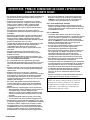
CAUTION
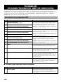
CAUTION: READ THIS BEFORE OPERATING YOUR UNIT.
• To assure the finest performance, please read this manual
carefully. Keep it in a safe place for future reference.
• Install this unit in a cool, dry, clean place — away from
windows, heat sources, sources of excessive vibration,
dust, moisture and cold. Avoid sources of humming
(transformers, motors). To prevent fire or electrical shock,
do not expose the unit to rain or water.
• Never open the cabinet. If something drops into the unit,
contact your dealer.
• Do not use force on switches, controls or connection
cables. When moving the unit, first set the power of the
front speaker unit to standby mode, disconnect the power
cord of the subwoofer and then the cables. Never pull the
cables themselves.
• Digital signals generated by this unit may interfere with
other component such as tuners, receivers and TVs. Move
this unit farther away from such component if interference
is observed.
• Do not attempt to clean the unit with chemical solvents;
this might damage the finish. Use a clean, dry cloth.
• Be sure to read the “TROUBLESHOOTING” section
regarding common operating errors before concluding that
the unit is faulty.
• When not planning to use this unit for a long period of time
(e.g., a vacation), disconnect the AC power cord of the
subwoofer from the wall outlet.
• To prevent lightning damage, disconnect the AC power
cord of the subwoofer when there is an electrical storm.
• Though the unit is a magnetic shielding type, there may be
some influence on a TV picture depending on the type of TV
or the placement of the unit. In such a case, place the unit
apart from the TV so that there is no influence on TV
picture.
• To prevent the enclosure from warping or discoloring, do
not place the unit where they will be exposed to direct
sunlight or excessive humidity.
• Do not place the following objects on top of the unit:
• Other components, as they might cause damage and/or
discoloration on the surface of the unit.
• Burning objects (i.e. candles), as they might cause fire,
damage to the unit and/or personal injury.
• Containers with liquid in them, as they might cause
electric shock to the user and/or damage to the unit.
• Do not place the unit where it is are liable to be knocked
over or struck by falling objects. Stable placement will also
ensure better sound performance.
• Secure placement or installation is the owner’s
responsibility. YAMAHA shall not be liable for any accident
caused by improper placement or installation of the unit.
• Do not attempt to modify or fix the unit. Contact qualified
YAMAHA service personnel when any service is needed.
The cabinet should never be opened for any reasons.
For the front speaker unit
•
Always set the volume to the minimum level before
starting the audio source play. Increase the volume
gradually to an appropriate level after playback has been
started.
For the subwoofer
•
The voltage used must be the same as that specified on
the rear panel. Using this unit with a higher voltage than
specified is dangerous and may result in fire or other
accidents. YAMAHA will not be held responsible for any
damage resulting from the use of this unit with a voltage
other than that specified.
• For heat release, be sure to allow a space of at least 10
cm above, behind and on both sides of the unit.
• Do not cover the rear panel of this unit with a newspaper,
a tablecloth, a curtain, etc. in order not to obstruct heat
radiation. If the temperature inside this unit rises, it may
cause fire, damage to this unit and/or personal injury.
• Do not plug in this unit to a wall outlet until all
connections are completed.
• Super-bass frequencies reproduced by this unit may
cause a turntable to generate a howling sound. In such a
case, move this unit away from the turntable.
• Vibration generated by super-bass frequencies may
distort images on a TV. In such a case, move this unit
away from the TV set.
• When disconnecting the power cord from the wall outlet,
grasp the plug; do not pull the cord.
This unit is not disconnected from the AC power source as long
as it is connected to the wall outlet, even if this unit itself is
turned off. This state is called the standby mode. In this state,
this unit is designed to consume a very small quantity of power.
■ For U.K. customers
If the socket outlets in the home are not suitable for the plug
supplied with this appliance, it should be cut off and an appropriate
3 pin plug fitted. For details, refer to the instructions described
below.
Note
• The plug severed from the mains lead must be destroyed, as a plug
with bared flexible cord is hazardous if engaged in a live socket
outlet.
■ Special Instructions for U.K. Model
IMPORTANT
THE WIRES IN MAINS LEAD ARE COLOURED IN
ACCORDANCE WITH THE FOLLOWING CODE:
Blue: NEUTRAL
Brown: LIVE
As the colours of the wires in the mains lead of this apparatus
may not correspond with the coloured markings identifying the
terminals in your plug, proceed as follows:
The wire which is coloured BLUE must be connected to the
terminal which is marked with the letter N or coloured
BLACK. The wire which is coloured BROWN must be
connected to the terminal which is marked with the letter L or
coloured RED.
Making sure that neither core is connected to the earth terminal
of the three pin plug.

English
REMOTE CONTROL
APPENDIX
PREPARATION
OPERATION
E-1
English
REMOTE CONTROL
APPENDIX
PREPARATION
OPERATION
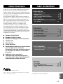
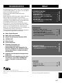
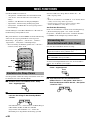
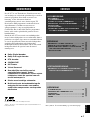
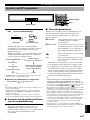
FEATURES
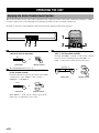
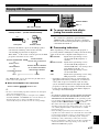
The AV-S77 is the Home Theater Sound System that
delivers a powerful and realistic sound experience like
that found in a movie theater just by combining the
front speaker unit with the TV.
The newest DSP programs will enhance the power
and realism of various sources, from movies to
concerts, and sporting events. Also, the Silent Cinema
program allows you to enjoy the sound field even
through the headphones.
Since the AV-S77 consists of a front speaker unit, rear
speakers and subwoofer, you can enjoy stronger bass
and surround effects as well as a good balance
throughout the speakers. Moreover, the One-touch
connection of the speaker cable designed exclusively
for this unit allows you to easily connect the speakers.
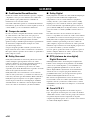
● Dolby Digital decoder
● Dolby Pro Logic decoder
● DTS (Digital Theater Systems) decoder
● CINEMA DSP
● Silent Cinema
● Virtual Surround
● Easy connection of the front speaker unit,
rear speakers and subwoofer using only
one speaker cable designed exclusively
for this unit
● Slim and powerful subwoofer
● Multi-function remote control which can
also be used for other audio/video
components of certain manufacturers
PREPARATION
Manufactured under license from Dolby Laboratories.
“Dolby”, “Pro Logic” and the double-D symbol are trademarks of Dolby
Laboratories.
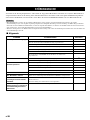
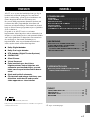
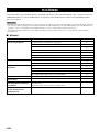
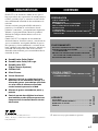
CONTENTS
y indicates a tip for your operation.
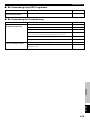
APPENDIX
GLOSSARY................................................................ 36
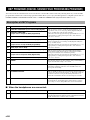
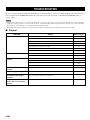
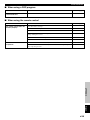
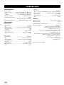
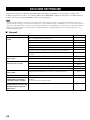
TROUBLESHOOTING ............................................ 38
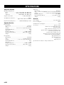
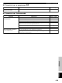
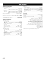
SPECIFICATIONS .................................................... 40
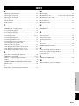
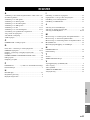
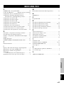
INDEX ........................................................................ 41
REMOTE CONTROL
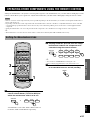
OPERATING OTHER COMPONENTS USING
THE REMOTE CONTROL .................................. 31
OPERATION
OPERATING THE UNIT ......................................... 22
USING CONVENIENT FUNCTIONS .................... 24
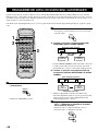
DSP PROGRAM (DIGITAL SOUND FIELD
PROCESSING PROGRAM) ................................. 26
MENU FUNCTIONS ................................................. 28
PREPARATION
FEATURES .................................................................. 1
GETTING STARTED ................................................. 2
NAMES OF ALL PARTS ............................................ 4
SPEAKER PLACEMENT .......................................... 6
INSTALLATION ......................................................... 7
CONNECTIONS ........................................................ 11
ADJUSTING THE SPEAKER
OUTPUT LEVELS ................................................. 20
“DTS” and “DTS Digital Surround” are registered trademarks of Digital
Theater Systems, Inc.

E-2
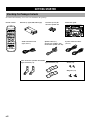
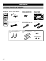
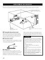
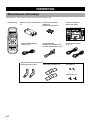
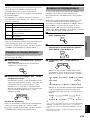
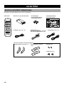
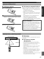
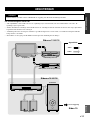
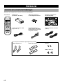
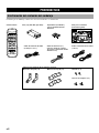
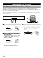
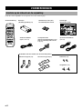
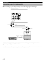
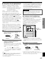
GETTING STARTED
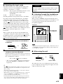
Checking the Package Contents
Check that the following accessories are included in the package.
Connection guideFasteners (2 sets) for
the front speaker unit
Audio connection cord
(2-pin, 3m x 1)
Batteries (x 2) (AA, R06, UM-3 type)Remote control
POWER —— MEMORY ——
AV-S77
123
MENU LEVEL TEST
DISPLAY
– +
EFFECT
ON/OFF
MUTE
NIGHT
h h
+
gg
h
qw
g
–
B. BOOST
POWER
INPUT
TV VOL
+
CH
–
CH
+
TV VOL
–
DSP VOL
1 2
TV MUTE
ENTER
3 4
5 6 7 8
sadw
tyer
CODE SET
DVD VCR TV
TV INPUT
TITLE MENU
Speaker cable (x 1)
(for the rear speakers: 15m,
for the front speaker unit: 3m)
Type A brackets (x 2) Type B brackets (x 2) Screws (x 2)
Wing nuts (x 2)
System connector cables
(3m x 2)
+– +–
VIDEO
OUT
AUDIO
OUT
L
R
L
R
OUTPUT
L
R
VIDEO
OUT
OPTICAL
DIGITAL
OUTPUT
OPTICAL
DIGITAL
OUTPUT
VIDEO
IN
AUDIO
IN
AUDIO
OUT
Rear speaker
Right
Rear speaker
Left
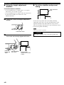
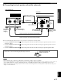
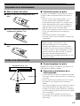
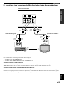
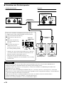
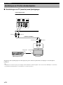
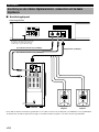
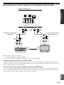
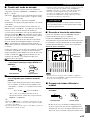
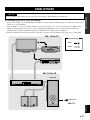
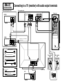
Connecting to a TV (monitor) with audio output terminals
When enjoying digital audio
DVD/LD
CD/MD
Audio connection cord (Analog signal) (x 1)
When there is no optical digital
output terminal
Accessories
Commercially available cord/cable
Optical digital cable (Digital signal)
Video connection cord
System connector cable (plug: black) (x 1)
Speaker cable (x 1)
System connector cable (plug: white) (x 1)
TV (monitor)
VCR
Subwoofer
MAINS
Front speaker unit
1
12
2
AUX TV
DIGITAL
INPUT
VIDEO
THROUGH
OUT
OPTICAL 1
(DTS/V/PCM)
OPTICAL 2
(DTS/V/PCM)
SYSTEM
CONNECTOR
SPEAKERS
(BLACK)
(WHITE)
MARKMARK
SPEAKERS
(BLACK)
MARK MARK
(WHITE)
PHONES
SYSTEM
CONNECTOR
DO NOT CONNECT THIS UNIT TO
SPEAKERS OTHER THAN AV-S77C,
NX-S77E
SILENT
R
L
R
L
V
R
L
V
V
L
R
L
R
L
R
Connection Guide
R
L
R
L
V V
1
23
V
Parts for the rear speakers installation

English
REMOTE CONTROL
APPENDIX
PREPARATION
OPERATION
E-3
AV-S7 7
– +
h h
+
gg
h
qw
g
–
sadw
tyer
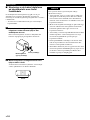
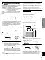
GETTING STARTED
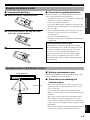
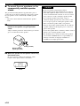
■ Precautions regarding batteries
Misuse of batteries may result in leakage or bursting. Be
sure to follow the precautions given below.
• Insert batteries with (+) and (–) oriented according to the
marking in the battery compartment.
• Do not mix old and new batteries.
• Do not mix different types of batteries as they may offer
different voltage and performance even though they have
the same shape.
• Remove all batteries if they can no longer be used or if
the remote control is not going to be used for an
extended period.
• Do not use rechargeable batteries.
• If leakage occurs, wipe away all battery fluid inside the
compartment.
Preserving the manufacturer code
Replace batteries early before they become unusable.
The manufacturer code set by the user will be preserved
for about two minutes when batteries run out or when
they are removed. Note that the manufacturer code
setting may be lost if more than two minutes elapses.
Also, if you press any button on the remote control
accidentally while replacing batteries, the manufacturer
code will be lost.
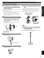
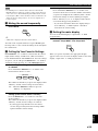
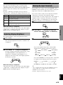
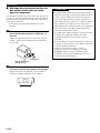
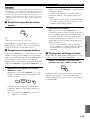
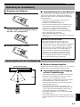
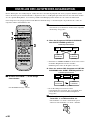
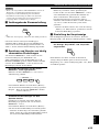
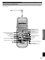
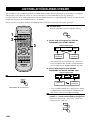
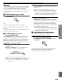
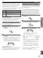
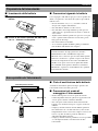
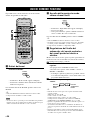
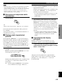
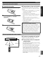
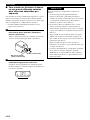
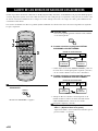
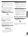
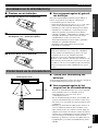
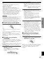
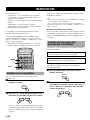
■ Inserting the batteries
1 Remove the battery compartment cover.
Readying the Remote Control
3 Close the battery compartment cover.
2 Insert the two batteries (AA, R06, UM-3 type)
with + and – oriented properly.
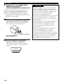
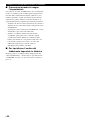
Operational Area of the Remote Control
■ Battery replacement cycle
Replace all two batteries when the operational range of the
remote control starts to become shorter.
■ Precautions on handling the
remote control
• The remote control may not be able to operate the front
speaker unit when an object blocks the remote control
sensor on the unit.
• Do not subject the remote control to impact. Do not
allow it to get wet or place it in a location subject to high
humidity.
• The remote control operations become difficult when
direct sunlight or other strong light (such as from an
inverter fluorescent lamp) strikes the sensor. Adjust the
relative positions of the light and the front speaker unit if
this happens.
• Remote control operations may not be possible if another
remote control is being operated at the same time.
Less than 6 m
30°30°
Front speaker unit

E-4
/I
STANDBY
INPUT DSP
–
VOLUME
+
/I
STANDBY
INPUT DSP
–
VOLUME
+
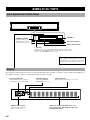
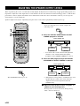
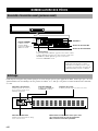
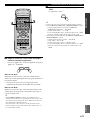
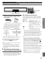
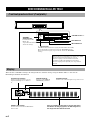
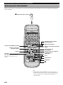
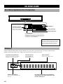
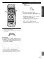
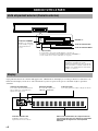
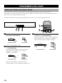
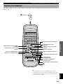
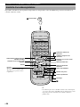
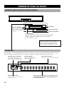
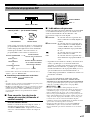
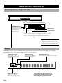
NAMES OF ALL PARTS
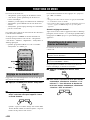
Front Speaker Unit (Front Panel)
p (power)
Turns the unit’s power on and standby. When the power switch is set to
standby mode, the STANDBY indicator is lit. When the power switch is
turned on, the STANDBY indicator goes off.
STANDBY indicator
Lights in standby mode.
When the power is turned
on, this indicator goes off.
VOLUME +/–
DSP selector button
INPUT selector button
When disconnecting and connecting the
power supply cord of the subwoofer, or when
restoring from a power failure, the unit returns
to the last power status (standby or power on).
VIRTUAL indicator
Lights when VIRTUAL
SURROUND is selected.
Phones indicator
Lights when the headphones are connected.
EFFECT OFF indicator
Lights when the sound field
effects is not turned on.
Shows the various information such as an
input source name, DSP program name, level
or operational status
Display
The display becomes brighter for a few seconds each time this unit is operated, even after you have adjusted the brightness of
the display to be dim, so that you can check the current operation clearly.
Processing indicators
Lights when the decoder or digital
sound field processor is functioning.

English
REMOTE CONTROL
APPENDIX
PREPARATION
OPERATION
E-5
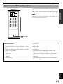
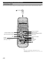
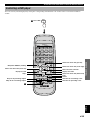
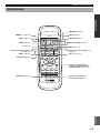
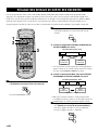
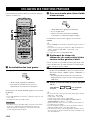
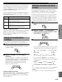
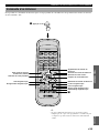
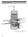
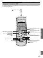
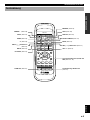
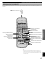
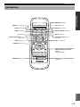
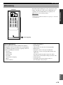
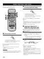
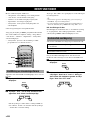
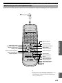
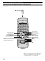
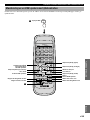
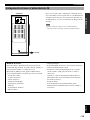
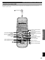
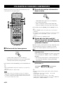
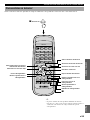
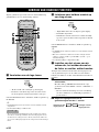
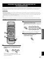
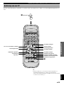
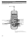
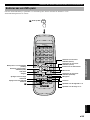
NAMES OF ALL PARTS
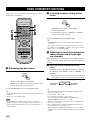
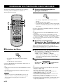
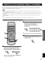
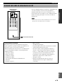
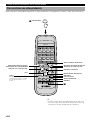
Remote Control
TEST (page 20)
INPUT selector buttons (
h
/
g
)
(page 22)
MUTE (page 25)
MEMORY (page 25)
NIGHT (page 24)
Remote control selector buttons
(page 31)
POWER p (page 20)
POWER —— MEMORY ——
AV-S77
123
MENU LEVEL TEST
DISPLAY
– +
EFFECT
ON/OFF
MUTE
NIGHT
h h
+
gg
h
qw
g
–
B. BOOST
POWER
INPUT
TV VOL
+
CH
–
CH
+
TV VOL
–
DSP VOL
1 2
TV MUTE
ENTER
3 4
5 6 7 8
sadw
tyer
CODE SET
DVD VCR TV
TV INPUT
TITLE MENU
LEVEL (page 24)
MENU (page 28)
–/+ (page 28)
B. BOOST (page 24)
CODE SET (page 31)
EFFECT ON/OFF (page 27)
DISPLAY (page 25)
VOL +/– (page 22)
DSP selector buttons (
h
/
g
)
(page 27)
TV, VCR or DVD operation buttons
(pages 33 - 35)

E-6
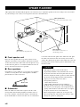
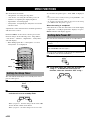
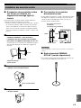
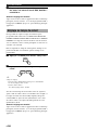
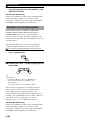
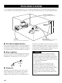
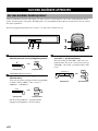
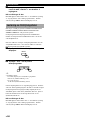
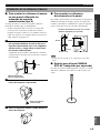
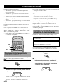
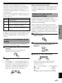
SPEAKER PLACEMENT
Although speakers should ideally be placed as shown below, try to adjust the speaker location according to the environment
of your listening room so that you can experience the best sound field effect.
Front speaker unit
Place above the monitor in the center.
About 1.8 m
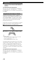
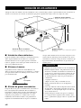
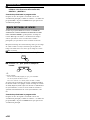
■ Subwoofer
Place the subwoofer either at the right or left side of the
front speaker unit and facing slightly toward the center of
the room so that the sound from it and the sound reflected
by the wall would not cancel each other out. As a transducer
■ Front speaker unit
Place the front speaker unit on top of the television and
align the front surface of the speakers with the front surface
of the television monitor. If the unit cannot be placed on top
of the television, place it on a rack beneath the television as
close to the television monitor as possible.
■ Rear speakers
Depending on room conditions, you can place rear speakers
on shelves or hang them on the wall. Speakers should be
placed about 1.8 m above the floor.
Rear speakers
Place behind or to the sides of
the listening position.
1.8 m
Right rear
speaker
Left rear
speaker
Subwoofer
Place near the front speaker unit.
is located on the left side panel of the subwoofer unit, place
the subwoofer unit more than 10 cm away from a wall or
curtain. Try altering the position of the subwoofer versus the
listening position as the relative position will affect the way
the bass sounds.
CAUTION
• Although the speaker system in this unit is
magnetically shielded, it may still affect the color on
the television monitor when using this unit near the
television. Adjust the relative positions of this unit and
the television if this happen. Perform the following
steps if you are using a television with a
demagnetizing function.
1 Turn off the television.
2 Wait awhile and turn the television back on.
• Install the speaker system in a well-ventilated place.
• Since there is a low frequency sound output from the
opening and transducer of the subwoofer, do not place
an object near these areas of the subwoofer.
• When transporting the subwoofer, do not put your
hand on the left side of the subwoofer. Doing so may
damage the speaker or grille panel.

English
REMOTE CONTROL
APPENDIX
PREPARATION
OPERATION
E-7
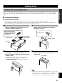
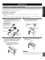
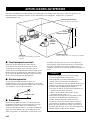
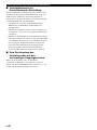
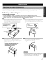
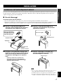
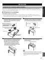
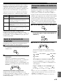
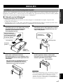
INSTALLATION
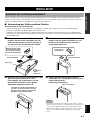
Installing the Front Speaker Unit
To prevent the front speaker unit from falling, secure it with the provided fastener when placing it on a television or other
device. Also, use the height adjustment bracket on the rear of the front speaker unit when there is a step on the installation
surface.
■ Using the fasteners
Precautions before installation
• Do not touch the adhesive surface after peeling off the strip as this will weaken its adhesive strength.
• Thoroughly wipe clean the surface where the fastener is to be applied. Note that adhesive strength is weakened if the
surface is dusty, oily or wet and that this may cause the front speaker unit to fall.
1 Peel off the seal of the fastener with the rough
surface and apply to the protrusions on the
bottom of the front speaker unit.
Note
• Once the front speaker unit is secured in this way, the paint on the
television surface used for installation may peel off when fastener
is removed later. Be sure to apply fasteners after carefully
checking the surface you are going to use for installation.
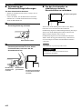
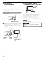
Press down.
4 Align the fasteners on both sides and firmly
press downward from the top of the front
speaker unit.
Smooth surface
Peel off the seal.
3 Peel off the seal of the fastener with the
smooth surface and apply to the positions
determined in step 2.
2 Place the front speaker unit where it is to be
installed (ex. on top of the television ) to
determine where to apply the fastener with the
smooth surface.
Protrusion
Front speaker
(bottom panel)
Rough surface
Wrap the fastener tightly
with sides of the tape well
aligned with the edges of
the protrusion.
Position it so that the fastener stuck to the front
speaker unit matches that of the fastener stuck to
the top of the television.

E-8
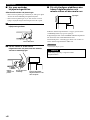
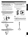
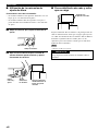
INSTALLATION
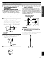
■ Using the height adjustment
brackets
Precautions before installation
• Do not install the unit on a tilted surface, or in a place
where there is not enough even space.
• Do not install the unit on a surface where the unit cannot
be placed horizontally even with the use of the
adjustment bracket.
1 Loosen the screws securing the adjustment
bracket.
■ To further stabilize and prevent
falling
Wire attachment
hole
Secure the front speaker unit to the wall by attaching
sufficiently strong wire to the wire attachment hole on the
adjustment bracket. This will double the safety measure
when used together with fasteners to prevent damage caused
by the front speaker unit falling.
Note
• Please provide wire separately.
CAUTION
Never place anything on top of the front speaker unit.
Place the front
speaker unit so that it
is level.
Securely tighten
the screws.
Lower the
bracket and
adjust.
2 Lower the bracket so that the front speaker
unit is level and securely tighten the screws.
Loosen the screws.

English
REMOTE CONTROL
APPENDIX
PREPARATION
OPERATION
E-9
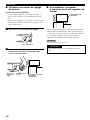
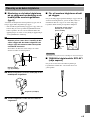
INSTALLATION
Note
• After mounting, check that the speakers are attached securely.
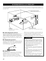
■ YAMAHA speaker stand SPS-AV1
(sold separately)
The rear speakers can also be attached to SPS-AV1 speaker
stands and used as floor stand speakers.
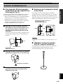
■ To mount speakers directly to the
wall
It is possible to hang the speakers directly on the wall
without using the mounting brackets by attaching two
protruding screws to the wall and then using the holes on
the rear panel of the speakers for direct attachment.
Protruding screws of about
4 to 5 mm in diameter
(commercially available)
70 mm70 mm
7 mm
20 mm or more
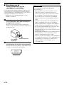
■ To mount the rear speakers on a
wall using the provided mounting
brackets (type A)
Use the provided mounting brackets (type A) when hanging
the rear speakers on a wall.
• When hanging the rear speakers on a wall, be sure to
connect the speaker cable to the rear speakers
beforehand. It is difficult to connect the rear speaker
cable after hanging. For details of the speaker cable
connection, refer to page 18.
1 Attach two commercially available protruding
screws (diameter about 4 mm) in the location
on the wall where the rear speaker is to be
hung, and then mount the bracket on the
protruding screws.
Check that the screws are secure inside the narrow
portion of the holes in the bracket.
65 mm
20 mm or more
Mounting bracket
(type A) (provided)
2 Attach the speaker to the bracket using the
provided wing nut.
Wing nut (provided)
3 Adjust the angle of the speaker and then
tighten the wing nut.
Installing the Rear Speakers

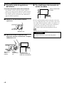
E-10
INSTALLATION
2 Mount the speaker on the speaker stand using
the bracket holes.
Be sure to prepare small screws (diameter: 4 mm,
length: 8 mm), spring washers and washers.
60 mm
Mounting bracket
(type B) (provided)
Screw (provided)
■ To mount the rear speakers on the
commercially available speaker
stands
The provided mounting brackets (type B) with 1 pair of
screw holes (at an interval of 60 mm) can be used to mount
the rear speakers on the commercially available speaker
stands.
• Also refer to the instructions manual for the speaker
stands.
1 Attach the mounting bracket (type B) to the
bottom of the speaker using the provided
screw.
Align so that the protrusion on the bracket goes into the
groove on the bottom of the speaker.
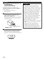
CAUTION
Be sure to read these important precautions.
• Each speaker weighs approximately 0.8 kg. Select a
firm wall or pillar to attach screws to. Do not attach
screws to material such as mortar or veneer as screws
may come loose easily, causing the speaker to fall.
• Do not mount speakers using nails or tape as
vibrations during operation may cause nails to come
loose or tape to peel off, causing the speaker to fall.
• Take care that the speaker cable is not pinched
between the speaker and the bracket. Be sure that the
speaker cable passes through the groove on the rear
panel of the speaker.
• Secure the speaker cables so that they will not catch on
hands or feet, causing speakers to fall.
• Be absolutely sure to check for safety after speakers
are mounted. YAMAHA bears no responsibility for
damage caused due to improper installation or
installation in an improper location.

English
REMOTE CONTROL
APPENDIX
PREPARATION
OPERATION
E-11
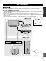
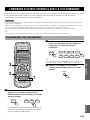
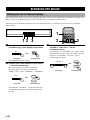
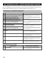
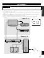
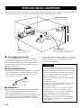
CAUTION
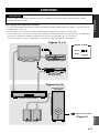
Plug the power cord of the subwoofer into a wall outlet when all connections are complete.
To ensure proper connections
• Connect the white plug of the connection cord to the left “L” (white) audio signal terminal and connect the red plug to the
right “R”(red) terminal.
• Insert the plug securely. If the plug is not inserted securely, noise may result or sound may not be output.
• Since the method of connection and terminal names differ depending on the component being used, be sure to refer to the
instruction manuals for all components being connected.
• After connections have been made, check one more time that wiring has been made properly.
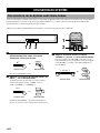
Subwoofer
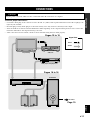
CONNECTIONS
TV (monitor) VCR, etc.
Pages 12 to 15
DVD player, LD player, etc.
Front speaker unit
AC outlet
Pages 16 to 18
Rear Speakers
Page 19
Video:
Audio:
Signal flow

E-12
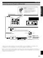
CONNECTIONS
RL
OUTPUT
AUX TV
DIGITAL
INPUT
VIDEO
THROUGH
OUT
OPTICAL 1
(DTS/V/PCM)
OPTICAL 2
(DTS/V/PCM)
AUDIO/VIDEO
IN
AUDIO/VIDEO
OUT
AUDIO OUT R AUDIO OUT L
R L
AUDIO IN RAUDIO IN L
R
L
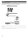
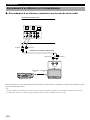
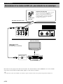
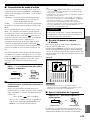
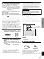
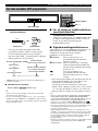
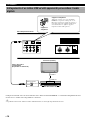
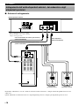
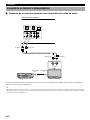
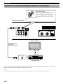
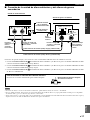
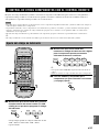
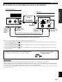
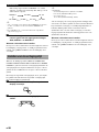
Connect the audio output terminal on the TV (monitor) to the TV terminal on the front speaker unit using the provided audio
connection cord.
y
• Television audio can be heard from the AV-S77. (Although you can also hear the audio using the TV speakers, we recommend you reduce
the TV volume so that you may enjoy the full benefit of the front speaker unit.)
VCR, etc. TV (monitor)
Audio connection cord (provided)
Front speaker unit
Connecting a TV or VCR
■ Connecting a TV (monitor) with audio output terminals

English
REMOTE CONTROL
APPENDIX
PREPARATION
OPERATION
E-13
CONNECTIONS
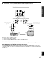
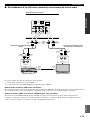
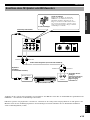
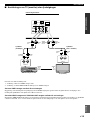
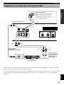
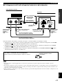
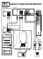
■ Connecting to a TV (monitor) without audio output terminals
Front speaker unit
RL
INPUT
RL
OUTPUT
AUX TV
DIGITAL
INPUT
VIDEO
THROUGH
OUT
OPTICAL 1
(DTS/V/PCM)
OPTICAL 2
(DTS/V/PCM)
VIDEO
IN
VIDEO
OUT
AUDIO
THROUGH
OUT L
R
L
AUDIO
IN R
AUDIO
THROUGH
OUT R
AUDIO
IN L
R
L
AUDIO
OUT R
AUDIO
OUT L
R
L
AUDIO
IN R
AUDIO
IN L
R L
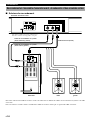
There are two methods of making connection:
1. connecting only the VIDEO terminals or
2. connecting the THROUGH OUT terminals in addition to the VIDEO terminals.
When only the VIDEO terminals are connected
Connect the audio output terminals on the VCR to the VIDEO terminals on the front speaker unit using the provided audio
connection cord. VCR audio may always be heard from the AV-S77.
When VIDEO terminals and THROUGH OUT terminals are connected
Connect the THROUGH OUT terminals on the front speaker unit to the audio input terminals on the TV (monitor) using a
commercially available audio connection cord. Audio can be heard from the TV speakers even when the front speaker unit is
in standby mode.
TV (monitor)
VCR, etc.
Audio connection cord
(commercially available)
Audio connection cord
(provided)

E-14
CONNECTIONS
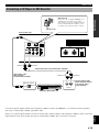
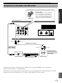
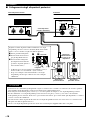
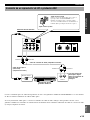
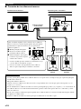
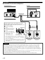
Connecting a DVD player, etc. to Enjoy Digital Audio
OPTICAL DIGITAL
OUTPUT
AUX TV
DIGITAL
INPUT
VIDEO
THROUGH
OUT
OPTICAL 1
(DTS/V/PCM)
OPTICAL 2
(DTS/V/PCM)
SYSTEM
CONNECTOR
SPEAKERS
(BLACK)
(WHITE)
MARKMARK
VIDEO OUT
VIDEO IN
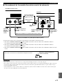
Connect the optical output terminal on the LD or DVD player to the DIGITAL 1 or 2 input terminal on the front speaker unit
using a commercially available optical fiber cable.
y
• The audio of the DVD or LD player can be heard from the AV-S77, but not from the TV speakers.
DVD player, LD player, etc.
Anti-dust cap
Remove the cap covering the DIGITAL 1or 2
terminal when connecting an optical fiber
cable. Safely store the cap and always re-insert
it in the terminal when the terminal is not in
use. (This cap prevents the entrance of dust.)
TV (monitor)
Optical fiber cable
(EIA standard)
(commercially available)
Front speaker unit
Anti-dust cap

English
REMOTE CONTROL
APPENDIX
PREPARATION
OPERATION
E-15
CONNECTIONS
Connecting a CD Player or MD Recorder
OPTICAL DIGITAL
OUTPUT
RL
OUTPUT
AUX TV
DIGITAL
INPUT
VIDEO
THROUGH
OUT
OPTICAL 1
(DTS/V/PCM)
OPTICAL 2
(DTS/V/PCM)
SYSTEM
CONNECTOR
SPEAKERS
(BLACK)
(WHITE)
MARKMARK
AUDIO OUT R AUDIO OUT L
AUDIO IN L AUDIO IN R
R L
R
L
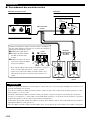
Connect the optical output terminal on the CD player or MD recorder to the DIGITAL 1 or 2 terminal on the front speaker
unit using a commercially available optical fiber cable.
If there is no optical output terminal, connect the analog audio output terminals on the CD player or MD recorder to the AUX
input terminals on the front speaker unit using a commercially available audio connection cord (2-pin).
CD player, MD recorder, etc.
Use the analog audio
output terminals if there
is no optical digital
output terminal.
Optical fiber cable
(EIA standard)
(commercially available)
Front speaker unit
Anti-dust cap
Remove the cap covering the DIGITAL 1or 2
terminal when connecting an optical fiber
cable. Safely store the cap and always re-insert
it in the terminal when the terminal is not in
use. (This cap prevents the entrance of dust.)
Anti-dust cap
Audio connection cord (commercially available)

E-16
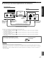
CONNECTIONS
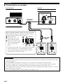
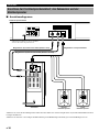
Connecting the Front Speaker Unit, Subwoofer and Rear Speakers
■ Connection layout
Front speaker unit
As this terminal is used for an
examination in the factory, do not
connect any equipment to this terminal.
System connector cable (plug: white) (provided)
System connector cable (plug: black) (provided)
Speaker cable (provided)
Subwoofer
Right rear speaker Left rear speaker
First, connect the front speaker unit and the subwoofer using the provided system connector cables and the speaker cable.
Then, connect the rear speakers using the rear speaker cables that are branched from the speaker cable.
SPEAKERS
(BLACK)
MARK MARK
(WHITE)
PHONES
SYSTEM
CONNECTOR
DO NOT CONNECT THIS UNIT TO
SPEAKERS OTHER THAN AV-S77C,
NX-S77E
SILENT
+– +–
MAINS
AUX TV
DIGITAL
INPUT
VIDEO
THROUGH
OUT
OPTICAL 1
(DTS/V/PCM)
OPTICAL 2
(DTS/V/PCM)
SYSTEM
CONNECTOR
SPEAKERS
(BLACK)
(WHITE)
MARKMARK

English
REMOTE CONTROL
APPENDIX
PREPARATION
OPERATION
E-17
SPEAKERS
PHONES
SYSTEM
CONNECTOR
DO NOT CONNECT THIS UNIT TO
SPEAKERS OTHER THAN AV-S77C,
NX-S77E
SILENT
MARK MARK
(WHITE)
(BLACK)
SYSTEM
CONNECTOR
SPEAKERS
(BLACK)
(WHITE)
MARKMARK
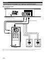
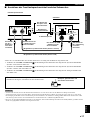
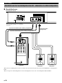
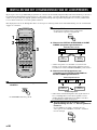
■ Connecting the front speaker unit and the subwoofer
Front speaker unit
Insert the connector
with its tab facing up.
Speaker cable
(provided)
Make sure that the plugs and connectors are positioned correctly before inserting them.
1. Connect SYSTEM CONNECTOR
on the front speaker unit and the subwoofer using the provided system connector
cable (plug: white).
2. Connect SYSTEM CONNECTOR
on the front speaker unit and the subwoofer using the provided system connector
cable (plug: black).
3. Connect SYSTEM CONNECTOR
on the front speaker unit and the subwoofer using the provided speaker cable.
To remove the connector of the speaker cable
Remove the connector while keeping the tab pressed down.
Notes
• Do not insert the plug or connector forcibly. Doing so may damage the plug, connector or terminal.
• Do not scratch, forcibly bend, or pull the system connector or speaker cable as this may damage the cable, causing loss of audio output, and
may possibly result in a fire or electric shock. Take particular care in making sure that the cable is not squashed by a rack or caster.
• Before disconnecting or connecting the system connector cable, set the front speaker unit to standby mode and then disconnect the power
supply cord of the subwoofer.
To
Insert the plug with
its b mark facing up.
Subwoofer
Insert the plug
with its b mark
facing up.
System connector cable (plug: black) (provided)
System connector cable (plug: white) (provided)
Keep pressing the tab and
remove the connector.
To
To
CONNECTIONS
To To
To
Insert the plug with
its b mark facing up.
Insert the
plug with its
b mark
facing up.
To the rear speakers

E-18
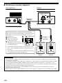
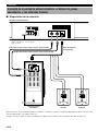
CONNECTIONS
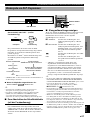
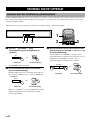
■ Connecting the rear speakers
Front speaker unit
Speaker cable
(provided)
Subwoofer
Speaker cable
identification
labels
Right rear speaker Left rear speaker
CAUTION
• Do not let the bare speaker wire touch each other and do not let them touch any metal part of the speakers. This could
damage the speakers.
• Do not mistakenly connect plus (+) to minus (–) or vice versa when connecting the rear speaker cables.
• Insert the rear speaker cables securely so that plus (+) and minus (–) do not short. The speaker may not output any
sound or may output noise, causing damage to the speakers, if speaker cables are not inserted securely.
• Insert only the bare wire portion of the speaker cables into the holes. Sound will not be output if you insert as far as the
plastic insulation part of the cable.
• Secure the rear speaker cables so that they will not catch on hands or feet.
SYSTEM
CONNECTOR
SPEAKERS
(BLACK)
(WHITE)
+––+
SPEAKERS
PHONES
SYSTEM
CONNECTOR
DO NOT CONNECT THIS UNIT TO
SPEAKERS OTHER THAN AV-S77C,
NX-S77E
SILENT
(BLACK)
MARK
MARK
(WHITE)
MARK
1
23
REAR R
REAR L
Remove the plastic insulation from the ends of the rear speaker
cable and twist the bare wires. (The bare wire will stay neat if
you twist while removing the plastic insulation.)
1 Hold down the tab.
2 Insert the bare wire of the
speaker cable into the hole.
3 Release the tab. (The tab will
return to its original position
when you release your
finger.)
• Connect the line-in cable to the + terminals (red) on the right,
and the other cable to the – terminals (black) on the left.
• Once connected, pull gently on the rear speaker cables to
check that they are connected securely.
Bare wire
Tab
Seite wird geladen ...
Seite wird geladen ...
Seite wird geladen ...
Seite wird geladen ...
Seite wird geladen ...
Seite wird geladen ...
Seite wird geladen ...
Seite wird geladen ...
Seite wird geladen ...
Seite wird geladen ...
Seite wird geladen ...
Seite wird geladen ...
Seite wird geladen ...
Seite wird geladen ...
Seite wird geladen ...
Seite wird geladen ...
Seite wird geladen ...
Seite wird geladen ...
Seite wird geladen ...
Seite wird geladen ...
Seite wird geladen ...
Seite wird geladen ...
Seite wird geladen ...
Seite wird geladen ...
Seite wird geladen ...
Seite wird geladen ...
Seite wird geladen ...
Seite wird geladen ...
Seite wird geladen ...
Seite wird geladen ...
Seite wird geladen ...
Seite wird geladen ...
Seite wird geladen ...
Seite wird geladen ...
Seite wird geladen ...
Seite wird geladen ...
Seite wird geladen ...
Seite wird geladen ...
Seite wird geladen ...
Seite wird geladen ...
Seite wird geladen ...
Seite wird geladen ...
Seite wird geladen ...
Seite wird geladen ...
Seite wird geladen ...
Seite wird geladen ...
Seite wird geladen ...
Seite wird geladen ...
Seite wird geladen ...
Seite wird geladen ...
Seite wird geladen ...
Seite wird geladen ...
Seite wird geladen ...
Seite wird geladen ...
Seite wird geladen ...
Seite wird geladen ...
Seite wird geladen ...
Seite wird geladen ...
Seite wird geladen ...
Seite wird geladen ...
Seite wird geladen ...
Seite wird geladen ...
Seite wird geladen ...
Seite wird geladen ...
Seite wird geladen ...
Seite wird geladen ...
Seite wird geladen ...
Seite wird geladen ...
Seite wird geladen ...
Seite wird geladen ...
Seite wird geladen ...
Seite wird geladen ...
Seite wird geladen ...
Seite wird geladen ...
Seite wird geladen ...
Seite wird geladen ...
Seite wird geladen ...
Seite wird geladen ...
Seite wird geladen ...
Seite wird geladen ...
Seite wird geladen ...
Seite wird geladen ...
Seite wird geladen ...
Seite wird geladen ...
Seite wird geladen ...
Seite wird geladen ...
Seite wird geladen ...
Seite wird geladen ...
Seite wird geladen ...
Seite wird geladen ...
Seite wird geladen ...
Seite wird geladen ...
Seite wird geladen ...
Seite wird geladen ...
Seite wird geladen ...
Seite wird geladen ...
Seite wird geladen ...
Seite wird geladen ...
Seite wird geladen ...
Seite wird geladen ...
Seite wird geladen ...
Seite wird geladen ...
Seite wird geladen ...
Seite wird geladen ...
Seite wird geladen ...
Seite wird geladen ...
Seite wird geladen ...
Seite wird geladen ...
Seite wird geladen ...
Seite wird geladen ...
Seite wird geladen ...
Seite wird geladen ...
Seite wird geladen ...
Seite wird geladen ...
Seite wird geladen ...
Seite wird geladen ...
Seite wird geladen ...
Seite wird geladen ...
Seite wird geladen ...
Seite wird geladen ...
Seite wird geladen ...
Seite wird geladen ...
Seite wird geladen ...
Seite wird geladen ...
Seite wird geladen ...
Seite wird geladen ...
Seite wird geladen ...
Seite wird geladen ...
Seite wird geladen ...
Seite wird geladen ...
Seite wird geladen ...
Seite wird geladen ...
Seite wird geladen ...
Seite wird geladen ...
Seite wird geladen ...
Seite wird geladen ...
Seite wird geladen ...
Seite wird geladen ...
Seite wird geladen ...
Seite wird geladen ...
Seite wird geladen ...
Seite wird geladen ...
Seite wird geladen ...
Seite wird geladen ...
Seite wird geladen ...
Seite wird geladen ...
Seite wird geladen ...
Seite wird geladen ...
Seite wird geladen ...
Seite wird geladen ...
Seite wird geladen ...
Seite wird geladen ...
Seite wird geladen ...
Seite wird geladen ...
Seite wird geladen ...
Seite wird geladen ...
Seite wird geladen ...
Seite wird geladen ...
Seite wird geladen ...
Seite wird geladen ...
Seite wird geladen ...
Seite wird geladen ...
Seite wird geladen ...
Seite wird geladen ...
Seite wird geladen ...
Seite wird geladen ...
Seite wird geladen ...
Seite wird geladen ...
Seite wird geladen ...
Seite wird geladen ...
Seite wird geladen ...
Seite wird geladen ...
Seite wird geladen ...
Seite wird geladen ...
Seite wird geladen ...
Seite wird geladen ...
Seite wird geladen ...
Seite wird geladen ...
Seite wird geladen ...
Seite wird geladen ...
Seite wird geladen ...
Seite wird geladen ...
Seite wird geladen ...
Seite wird geladen ...
Seite wird geladen ...
Seite wird geladen ...
Seite wird geladen ...
Seite wird geladen ...
Seite wird geladen ...
Seite wird geladen ...
Seite wird geladen ...
Seite wird geladen ...
Seite wird geladen ...
Seite wird geladen ...
Seite wird geladen ...
Seite wird geladen ...
Seite wird geladen ...
Seite wird geladen ...
Seite wird geladen ...
Seite wird geladen ...
Seite wird geladen ...
Seite wird geladen ...
Seite wird geladen ...
Seite wird geladen ...
Seite wird geladen ...
Seite wird geladen ...
Seite wird geladen ...
Seite wird geladen ...
Seite wird geladen ...
Seite wird geladen ...
Seite wird geladen ...
Seite wird geladen ...
Seite wird geladen ...
Seite wird geladen ...
Seite wird geladen ...
Seite wird geladen ...
Seite wird geladen ...
Seite wird geladen ...
Seite wird geladen ...
Seite wird geladen ...
Seite wird geladen ...
Seite wird geladen ...
Seite wird geladen ...
Seite wird geladen ...
Seite wird geladen ...
Seite wird geladen ...
Seite wird geladen ...
Seite wird geladen ...
Seite wird geladen ...
Seite wird geladen ...
Seite wird geladen ...
Seite wird geladen ...
Seite wird geladen ...
Seite wird geladen ...
Seite wird geladen ...
Seite wird geladen ...
Seite wird geladen ...
Seite wird geladen ...
Seite wird geladen ...
Seite wird geladen ...
Seite wird geladen ...
Seite wird geladen ...
Seite wird geladen ...
Seite wird geladen ...
Seite wird geladen ...
Seite wird geladen ...
Seite wird geladen ...
Seite wird geladen ...
Seite wird geladen ...
Seite wird geladen ...
Seite wird geladen ...
Seite wird geladen ...
Seite wird geladen ...
Seite wird geladen ...
Seite wird geladen ...
Seite wird geladen ...
Seite wird geladen ...
Seite wird geladen ...
Seite wird geladen ...
Seite wird geladen ...
Seite wird geladen ...
Seite wird geladen ...
Seite wird geladen ...
Seite wird geladen ...
Seite wird geladen ...
Seite wird geladen ...
Seite wird geladen ...
Seite wird geladen ...
Seite wird geladen ...
Seite wird geladen ...
Seite wird geladen ...
Seite wird geladen ...
Seite wird geladen ...
Seite wird geladen ...
Seite wird geladen ...
Seite wird geladen ...
Seite wird geladen ...
Seite wird geladen ...
-
 1
1
-
 2
2
-
 3
3
-
 4
4
-
 5
5
-
 6
6
-
 7
7
-
 8
8
-
 9
9
-
 10
10
-
 11
11
-
 12
12
-
 13
13
-
 14
14
-
 15
15
-
 16
16
-
 17
17
-
 18
18
-
 19
19
-
 20
20
-
 21
21
-
 22
22
-
 23
23
-
 24
24
-
 25
25
-
 26
26
-
 27
27
-
 28
28
-
 29
29
-
 30
30
-
 31
31
-
 32
32
-
 33
33
-
 34
34
-
 35
35
-
 36
36
-
 37
37
-
 38
38
-
 39
39
-
 40
40
-
 41
41
-
 42
42
-
 43
43
-
 44
44
-
 45
45
-
 46
46
-
 47
47
-
 48
48
-
 49
49
-
 50
50
-
 51
51
-
 52
52
-
 53
53
-
 54
54
-
 55
55
-
 56
56
-
 57
57
-
 58
58
-
 59
59
-
 60
60
-
 61
61
-
 62
62
-
 63
63
-
 64
64
-
 65
65
-
 66
66
-
 67
67
-
 68
68
-
 69
69
-
 70
70
-
 71
71
-
 72
72
-
 73
73
-
 74
74
-
 75
75
-
 76
76
-
 77
77
-
 78
78
-
 79
79
-
 80
80
-
 81
81
-
 82
82
-
 83
83
-
 84
84
-
 85
85
-
 86
86
-
 87
87
-
 88
88
-
 89
89
-
 90
90
-
 91
91
-
 92
92
-
 93
93
-
 94
94
-
 95
95
-
 96
96
-
 97
97
-
 98
98
-
 99
99
-
 100
100
-
 101
101
-
 102
102
-
 103
103
-
 104
104
-
 105
105
-
 106
106
-
 107
107
-
 108
108
-
 109
109
-
 110
110
-
 111
111
-
 112
112
-
 113
113
-
 114
114
-
 115
115
-
 116
116
-
 117
117
-
 118
118
-
 119
119
-
 120
120
-
 121
121
-
 122
122
-
 123
123
-
 124
124
-
 125
125
-
 126
126
-
 127
127
-
 128
128
-
 129
129
-
 130
130
-
 131
131
-
 132
132
-
 133
133
-
 134
134
-
 135
135
-
 136
136
-
 137
137
-
 138
138
-
 139
139
-
 140
140
-
 141
141
-
 142
142
-
 143
143
-
 144
144
-
 145
145
-
 146
146
-
 147
147
-
 148
148
-
 149
149
-
 150
150
-
 151
151
-
 152
152
-
 153
153
-
 154
154
-
 155
155
-
 156
156
-
 157
157
-
 158
158
-
 159
159
-
 160
160
-
 161
161
-
 162
162
-
 163
163
-
 164
164
-
 165
165
-
 166
166
-
 167
167
-
 168
168
-
 169
169
-
 170
170
-
 171
171
-
 172
172
-
 173
173
-
 174
174
-
 175
175
-
 176
176
-
 177
177
-
 178
178
-
 179
179
-
 180
180
-
 181
181
-
 182
182
-
 183
183
-
 184
184
-
 185
185
-
 186
186
-
 187
187
-
 188
188
-
 189
189
-
 190
190
-
 191
191
-
 192
192
-
 193
193
-
 194
194
-
 195
195
-
 196
196
-
 197
197
-
 198
198
-
 199
199
-
 200
200
-
 201
201
-
 202
202
-
 203
203
-
 204
204
-
 205
205
-
 206
206
-
 207
207
-
 208
208
-
 209
209
-
 210
210
-
 211
211
-
 212
212
-
 213
213
-
 214
214
-
 215
215
-
 216
216
-
 217
217
-
 218
218
-
 219
219
-
 220
220
-
 221
221
-
 222
222
-
 223
223
-
 224
224
-
 225
225
-
 226
226
-
 227
227
-
 228
228
-
 229
229
-
 230
230
-
 231
231
-
 232
232
-
 233
233
-
 234
234
-
 235
235
-
 236
236
-
 237
237
-
 238
238
-
 239
239
-
 240
240
-
 241
241
-
 242
242
-
 243
243
-
 244
244
-
 245
245
-
 246
246
-
 247
247
-
 248
248
-
 249
249
-
 250
250
-
 251
251
-
 252
252
-
 253
253
-
 254
254
-
 255
255
-
 256
256
-
 257
257
-
 258
258
-
 259
259
-
 260
260
-
 261
261
-
 262
262
-
 263
263
-
 264
264
-
 265
265
-
 266
266
-
 267
267
-
 268
268
-
 269
269
-
 270
270
-
 271
271
-
 272
272
-
 273
273
-
 274
274
-
 275
275
-
 276
276
-
 277
277
-
 278
278
-
 279
279
-
 280
280
-
 281
281
-
 282
282
-
 283
283
-
 284
284
-
 285
285
-
 286
286
-
 287
287
-
 288
288
-
 289
289
-
 290
290
-
 291
291
-
 292
292
-
 293
293
-
 294
294
-
 295
295
-
 296
296
-
 297
297
-
 298
298


in anderen Sprachen
- English: Yamaha AV-S77 Owner's manual
- français: Yamaha AV-S77 Le manuel du propriétaire
- español: Yamaha AV-S77 El manual del propietario
- italiano: Yamaha AV-S77 Manuale del proprietario
- Nederlands: Yamaha AV-S77 de handleiding
- dansk: Yamaha AV-S77 Brugervejledning
- svenska: Yamaha AV-S77 Bruksanvisning
- Türkçe: Yamaha AV-S77 El kitabı
- română: Yamaha AV-S77 Manualul proprietarului