Yamaha SWR2310 Bedienungsanleitung
- Kategorie
- Vernetzung
- Typ
- Bedienungsanleitung

L2 SWITCH
IT
RU
ZH
KO
PT
ES
FR
DE
EN
Owner’s Manual
Bedienungsanleitung
Mode d’emploi
Manual de instrucciones
Manual de instruções
Manuale di istruzioni
Руководство пользователя
칺푷컲졓컪
SWR2310-28GT
SWR2310-18GT
SWR2310-10G
EnglishDeutschFrançaisEspañolPortuguêsItalianoItaliano묻펂 Русский

2 SWR2310-28GT SWR2310-18GT SWR2310-10G
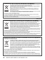
Explanation of Graphical Symbols
Explication des symboles
The lightning flash with arrowhead symbol within an equilateral triangle is intended to alert the user to the presence of uninsulated
“dangerous voltage” within the product’s enclosure that may be of sufficient magnitude to constitute a risk of electric shock to persons.
L’éclair avec une flèche à l’intérieur d’un triangle équilatéral est destiné à attirer l’attention de l’utilisateur sur la présence d’une
« tension dangereuse» non isolée à l’intérieur de l’appareil, pouvant être suffisamment élevée pour constituer un risque d’électrocution.
The exclamation point within an equilateral triangle is intended to alert the user to the presence of important operating and maintenance
(servicing) instructions in the literature accompanying the product.
Le point d’exclamation à l’intérieur d’un triangle équilatéral est destiné à attirer l’attention de l’utilisateur sur la présence d’instructions
importantes sur l’emploi ou la maintenance (réparation) de l’appareil dans la documentation fournie.
IMPORTANT SAFETY
INSTRUCTIONS
1 Read these instructions.
2 Keep these instructions.
3 Heed all warnings.
4 Follow all instructions.
5 Do not use this apparatus near water.
6 Clean only with dry cloth.
7 Do not block any ventilation openings. Install in accordance with
the manufacturer’s instructions.
8 Do not install near any heat sources such as radiators, heat
registers, stoves, or other apparatus (including amplifiers) that
produce heat.
9 Do not defeat the safety purpose of the polarized or grounding-
type plug. A polarized plug has two blades with one wider than the
other. A grounding type plug has two blades and a third grounding
prong. The wide blade or the third prong are provided for your
safety. If the provided plug does not fit into your outlet, consult an
electrician for replacement of the obsolete outlet.
10 Protect the power cord from being walked on or pinched
particularly at plugs, convenience receptacles, and the point where
they exit from the apparatus.
11 Only use attachments/accessories specified by the manufacturer.
12 Use only with the cart, stand, tripod, bracket, or
table specified by the manufacturer, or sold with
the apparatus. When a cart is used, use caution
when moving the cart/apparatus combination to
avoid injury from tip-over.
13 Unplug this apparatus during lightning storms or
when unused for long periods of time.
14 Refer all servicing to qualified service personnel. Servicing is
required when the apparatus has been damaged in any way, such
as power-supply cord or plug is damaged, liquid has been spilled
or objects have fallen into the apparatus, the apparatus has been
exposed to rain or moisture, does not operate normally, or has
been dropped.
PRÉCAUTIONS CONCER-
NANT LA SÉCURITÉ
1 Lire ces instructions.
2 Conserver ces instructions.
3 Tenir compte de tous les avertissements.
4 Suivre toutes les instructions.
5 Ne pas utiliser ce produit à proximité d’eau.
6 Nettoyer uniquement avec un chiffon propre et sec.
7 Ne pas bloquer les orifices de ventilation. Installer l’appareil
conformément aux instructions du fabricant.
8 Ne pas installer l’appareil à proximité d’une source de chaleur
comme un radiateur, une bouche de chaleur, un poêle ou tout autre
appareil (y compris un amplificateur) produisant de la chaleur.
9 Ne pas modifier le système de sécurité de la fiche polarisée ou de
la fiche de terre. Une fiche polarisée dispose de deux broches dont
une est plus large que l’autre. Une fiche de terre dispose de deux
broches et d’une troisième pour le raccordement à la terre. Cette
broche plus large ou cette troisième broche est destinée à assurer
la sécurité de l’utilisateur. Si la fiche équipant l’appareil n’est pas
compatible avec les prises de courant disponibles, faire remplacer
les prises par un électricien.
10 Acheminer les cordons d’alimentation de sorte qu’ils ne soient pas
piétinés ni coincés, en faisant tout spécialement attention aux
fiches, prises de courant et au point de sortie de l’appareil.
11 Utiliser exclusivement les fixations et accessoires spécifiés par le
fabricant.
12 Utiliser exclusivement le chariot, le stand, le
trépied, le support ou la table recommandés par
le fabricant ou vendus avec cet appareil. Si
l’appareil est posé sur un chariot, déplacer le
chariot avec précaution pour éviter tout risque
de chute et de blessure.
13 Débrancher l’appareil en cas d’orage ou lorsqu’il
doit rester hors service pendant une période prolongée.
14 Confier toute réparation à un personnel qualifié. Faire réparer
l’appareil s’il a subi tout dommage, par exemple si la fiche ou le
cordon d’alimentation est endommagé, si du liquide a coulé ou des
objets sont tombés à l’intérieur de l’appareil, si l’appareil a été
exposé à la pluie ou à de l’humidité, si l’appareil ne fonctionne pas
normalement ou est tombé.
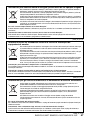
CAUTION:
TO REDUCE THE RISK OF ELECTRIC SHOCK,
DO NOT REMOVE COVER (OR BACK).
NO USER-SERVICEABLE PARTS INSIDE.
REFER SERVICING TO QUALIFIED SERVICE PERSONNEL.
ATTENTION :
POUR RÉDUIRE LES RISQUES D'ÉLECTROCUTION, NE PAS RETIRER
LE CAPOT (OU LE DOS). NE CONTIENT PAS DE PIÈCES NÉCESSITANT
L'INTERVENTION DE L'UTILISATEUR. POUR TOUTE INTERVENTION,
FAIRE APPEL À DES PROFESSIONNELS QUALIFIÉS.
ATTENTION
RISQUE DE CHOC
ELECTRIQUE-NE PAS OUVRIR
The above warning is located on the top of the unit. L’avertissement ci-dessus est situé sur le dessus de l’unité.
WARNING
TO REDUCE THE RISK OF FIRE OR ELECTRIC SHOCK, DO NOT
EXPOSE THIS APPARATUS TO RAIN OR MOISTURE.
AVERTISSEMENT
POUR RÉDUIRE LES RISQUES D’INCENDIE OU DE DÉCHARGE
ÉLECTRIQUE, N’EXPOSEZ PAS CET APPAREIL À LA PLUIE OU À
L’HUMIDITÉ.

English
SWR2310-28GT SWR2310-18GT SWR2310-10G 3
1. IMPORTANT NOTICE:
DO NOT MODIFY THIS UNIT!
This product, when installed as indicated
in the instructions contained in this
manual, meets FCC requirements.
Modifications not expressly approved by
Yamaha may void your authority, granted
by the FCC, to use the product.
2. IMPORTANT: When connecting this
product to accessories and/ or another
product use only high quality shielded
cables. Cable/s supplied with this product
MUST be used. Follow all installation
instructions. Failure to follow instructions
could void your FCC authorization to use
this product in the USA.
3. NOTE: This equipment has been tested
and found to comply with the limits for a
Class A digital device, pursuant to Part 15
of the FCC rules. These limits are
designed to provide reasonable protection
against harmful interference when the
equipment is operated in a commercial
environment. This equipment generates,
uses and can radiate radio frequency
energy and, if not installed and used in
accordance with the instruction manual,
may cause harmful interference to radio
communications. Operation of this
equipment in a residential area is likely to
cause harmful interference in which case
the user will be required to correct the
interference at his own expense.
FCC INFORMATION (U.S.A.)
Responsible Party: Yamaha Corporation of America
Address: 6600 Orangethorpe Ave. Buena Park CA90620
Telephone: 714-522-9011
Type of Equipment: L2 SWITCH
Model Name: SWR2310-28GT, SWR2310-18GT, SWR2310-10G
This device complies with Part 15 of the FCC Rules.
Operation is subject to the following conditions:
1) this device may not cause harmful interference, and
2) this device must accept any interference received including interference that may cause
undesired operation.
See user manual instructions if interference to radio reception is suspected.
COMPLIANCE INFORMATION STATEMENT
(Supplierʼs declaration of conformity procedure)
(class A)
(FCC SDoC)

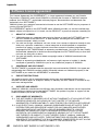
4 SWR2310-28GT SWR2310-18GT SWR2310-10G
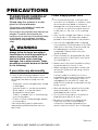
PRECAUTIONS
PLEASE READ CAREFULLY
BEFORE PROCEEDING
Please keep this manual in a safe
place for future reference.
This product is an intelligent L2 switch with
optimal functionality for Dante.
Do not use for any purposes other than the one
intended. Those who are unfamiliar with
handling or those who can not handle according
to this manual such as children, should be
supervised by responsible persons to ensure
safety.
WARNING
Always follow the basic precautions
listed below to avoid the possibility of
serious injury or even death from
electrical shock, short-circuiting,
damages, fire or other hazards. These
precautions include, but are not limited
to, the following:
If you notice any abnormality
• If any of the following problems occur,
immediately turn off the power switch and
disconnect the electric plug from the
outlet.
- The power cord or plug becomes frayed
or damaged.
- Unusual smells or smoke are emitted.
- Some object, or water has been
dropped into the product.
- There is a sudden loss of sound during
use of the product.
- Cracks or other visible damage appear
on the product.
Then have the product inspected or
repaired by qualified Yamaha service
personnel.
Power supply/power cord
• Do not place the power cord near heat
sources such as heaters or radiators, and
do not excessively bend or otherwise
damage the cord, place heavy objects on
it, or place it in a position where anyone
could walk on, trip over, or roll anything
over it.
• Only use the voltage specified as correct
for the product. The required voltage is
printed on the name plate of the product.
• Use only the supplied power cord/plug.
If you intend to use the product in an area
other than in the one you purchased, the
included power cord may not be
compatible. Please check with your
Yamaha dealer.
• Check the electric plug periodically and
remove any dirt or dust which may have
accumulated on it.
• Make sure to fully insert the electric plug
to prevent electric shocks or fire.
• When setting up the product, make sure
that the AC outlet you are using is easily
accessible.
If some trouble or malfunction occurs,
immediately disconnect the plug from the
outlet. As long as the power cord is not
unplugged from the wall AC outlet, the
product will not be disconnected from the
power source.
• Remove the electric plug from the outlet
when the product is not to be used for
extended periods of time.
• Do not touch the product or the electric
plug during an electrical storm.
• Be sure to connect to an appropriate
outlet with a protective grounding
connection. Improper grounding can
result in electrical shock, fire, or damage.
PA11- 1/4

English
SWR2310-28GT SWR2310-18GT SWR2310-10G 5
Do not open
• This product contains no user-serviceable
parts. Do not attempt to disassemble the
internal parts or modify them in any way.
Water warning/Fire warning
• Do not expose the product to rain, use it
near water or in damp or wet conditions,
or place on it any containers (such as
vases, bottles or glasses) containing
liquids which might spill into any
openings.
• Never insert or remove an electric plug
with wet hands.
• Do not place any burning items or open
flames near the product, since they may
cause a fire.
CAUTION
Always follow the basic precautions
listed below to avoid the possibility of
physical injury to you or others. These
precautions include, but are not limited
to, the following:
Power supply/power cord
• When removing the electric plug from the
product or an outlet, always hold the plug
itself and not the cord. Pulling by the cord
can damage it.
Location and connection
• Do not place the product in an unstable
position or a location with excessive
vibration, where it might accidentally fall
over and cause injury.
• Keep the device and small parts out of
reach of children, to keep them from
putting their fingers into openings on the
product and accidentally being injured.
This product is not suitable for use in
locations where children are likely to be
present.
•
Do not block the vents. This product has
ventilation holes at the top (SWR2310-10G
only)/sides to prevent the internal
temperature from becoming too high. In
particular, do not place the product on its
side or upside down. Inadequate ventilation
can result in overheating, possibly causing
damage to the product(s), or even fire.
• When installing the product:
- Do not cover it with any cloth.
- Do not install it on a carpet or rug.
- Make sure the top or side surface faces
up; do not install on its front, rear, or
upside down.
- Do not use the product in a confined,
poorly-ventilated location.
Inadequate ventilation can result in
overheating, possibly causing damage to
the product(s), or even fire.
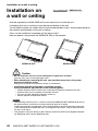
• When using the separately sold WK-SWR
wall mount accessory, do not install the
SWR2310-18GT, SWR2310-10G on a wall
or ceiling that is more than 2 meters high.
The product might fall, causing
malfunction or injury.
• If the product is mounted in an EIA
standard rack, carefully read the section
“Please read before mounting the unit into
a rack” on page 20. Inadequate
ventilation can result in overheating,
possibly causing damage to the
product(s), malfunction, or even fire.
• Do not place the product in a location
where it may come into contact with
corrosive gases or salt air. Doing so may
result in malfunction.
• Before moving the product, remove all
connected cables.
• Always consult qualified Yamaha service
personnel if the product installation
requires construction work, and make
sure to observe the following precautions.
- Choose mounting hardware and an
installation location that can support the
weight of the product.
- Avoid locations that are exposed to
constant vibration.
- Use the required tools to install the
product.
- Inspect the product periodically.
PA11- 2/4

6 SWR2310-28GT SWR2310-18GT SWR2310-10G
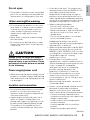
Maintenance
• Remove the power plug from the AC
outlet when cleaning the product.
Handling caution
• Do not insert your fingers or hands in any
gaps or openings on the product (vents,
ports, panel, etc.).
• Do not rest your weight on the product or
place heavy objects on it.
•
Do not look into the optical emitter when a
separately sold SFP module
(SFP-SWRG-SX, SFP-SWRG-LX) and/or
SFP+ module (SFP-SWRT-SR,
SFP-SWRT-LR) is installed. The separately
sold SFP/SFP+ modules are class 1 laser
devices. They may emit laser beams
invisible to the eye. If the laser beam
enters your eye, your eyesight might be
damaged.
Backup battery
• Do not replace the backup battery by
yourself. Doing so may cause an
explosion and/or damage to the
product(s).
When the backup battery needs to be
replaced, contact your Yamaha dealer
and have qualified Yamaha service
personnel replace the backup battery.
Yamaha cannot be held responsible for
damage caused by improper use or
modifications to the product, or data
that is lost or destroyed.
PA11- 3/4

English
SWR2310-28GT SWR2310-18GT SWR2310-10G 7
NOTICE
To avoid the possibility of malfunction/ damage
to the product, damage to data, or damage to
other property, follow the notices below.
Handling and maintenance
• Do not touch the interior of a port with your
fingers or any metallic object. Doing so
might cause malfunctions.
• Do not use the product in a location
exposed to direct sunlight (such as in a car
during the day), in a location of extreme
heat such as near a stove, in a location of
extreme cold, or in a location of excessive
dust or vibration. Failure to observe this
precaution could cause the product’s
panel to deform, its interior components to
malfunction, or its operation to become
unstable.
• Do not place vinyl, plastic or rubber
objects on the product, since this might
cause alteration or discoloration of the
panel.
• When cleaning the product, use a dry and
soft cloth. Do not use paint thinners,
solvents, cleaning fluids, or chemical-
impregnated wiping cloths, since this might
cause alteration or discoloration.
• Condensation can occur in the product due
to rapid, drastic changes in ambient
temperature—when the product is moved
from one location to another, or air
conditioning is turned on or off, for example.
Using the product while condensation is
present can cause damage. If there is
reason to believe that condensation might
have occurred, leave the product for several
hours without turning on the power until the
condensation has completely dried out.
• Drain all static electricity from your
clothing and body before handling this
product. Static electricity can damage this
product. Touch an exposed metal part of
the host device or other grounded object
beforehand.
• Do not install the product in a location
where magnetic fields are strong.
Otherwise, it might cause the product to
malfunction.
• Do not connect any noise generating
devices on the same power line as the
product. Failure to observe this precaution
could result in a malfunction or damage to
the product.
• Do not locate any connected LAN cables
close to the power cord. Otherwise, high
voltage might be induced, resulting in
malfunction.
• A 1000BASE-T connection will require an
Enhanced Category 5 (CAT5e) or better
LAN cable.
• Do not install any SFP module other than
the separately sold SFP-SWRG-SX or
SFP-SWRG-LX in an SFP port. Operation
cannot be guaranteed if any SFP module
other than the above is installed.
• Do not install any SFP+ module other than
the separately sold SFP-SWRT-SR or
SFP-SWRT-LR, any SFP module other
than the SFP-SWRG-LX or
SFP-SWRG-SX, or any direct attach cable
other than the DAC-SWRT-3M or
DAC-SWRT-1M in an SFP+ port.
Operation cannot be guaranteed if any
module or cable other than the above is
installed.
• Attach the dust cover to SFP/SFP+ ports
that are not in use. Failing to do so could
allow foreign objects to enter, causing
malfunctions. Keep the dust cover in a
safe place so that it is not lost.
• The rubber feet included in this package
can be attached to the product to prevent
slippage when it is to be used on a
slippery surface.
• Do not connect this product to public Wi-Fi
and/or Internet directly. Only connect this
product to the Internet through a router
with strong password-protections. Consult
your router manufacturer for information
on security best practices.

8 SWR2310-28GT SWR2310-18GT SWR2310-10G
Saving data
• This unit has a built-in backup battery that
maintains time information for the data.
When the backup battery runs down, the
time information will be initialized, causing
incorrect time information to be recorded in
the log. If this occurs, contact your dealer
or a Yamaha customer service center to
have the backup battery replaced. The life
span of the backup battery is
approximately 10 years, but this may vary
depending on the conditions of use. Set
the clock after replacing the battery.
Functions/data bundled with the
product
• This is a class A product. Operation of this
product in a residential environment could
cause radio interference.
About disposal
• This product contains recyclable
components. When disposing of this
product, please contact the appropriate
local authorities.
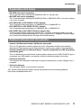
About this manual
• The illustrations and screens as shown in
this manual are for instructional purposes
only.
• Windows is a registered trademark of
Microsoft
®
Corporation in the United
States and other countries.
• The company names and product names
in this manual are the trademarks or
registered trademarks of their respective
companies.
• Software may be revised and updated
without prior notice.
Open source software used in this
product
• Please refer to the Yamaha Pro Audio
website for the licensing terms.
http://www.yamaha.com/proaudio/
Warning: Fiber Optic Port Safety
This product is intended to be installed in an UL
certified Optical Transceiver Module, rated 3.3V,
Laser Class 1, if need further assistance,
please contact Yamaha Corporation for further
information.
° Icons
Information that applies to the SWR2310-28GT, SWR2310-18GT, or SWR2310-10G is
indicated by the following icons.
Indicates information that applies only to the SWR2310-28GT.
Indicates information that applies only to the SWR2310-18GT.
Indicates information that applies only to the SWR2310-10GT.
Memo
An icon is not shown for information that is common to all models.
Conventions in this document
Company names and product names in this document are abbreviated as follows.
• Yamaha SWR2310-28GT, SWR2310-18GT, or SWR2310-10G L2 switch: this product
• 10BASE-T/100BASE-TX/1000BASE-T cable: LAN cable
• SFP-SWRT-SR or SFP-SWRT-LR: SFP+ module
• SFP-SWRG-SX or SFP-SWRG-LX: SFP module
• DAC-SWRT-3M or DAC-SWRT-1M: direct attach cable
SWR2310-28GT
SWR2310-18GT
SWR2310-10G

English
SWR2310-28GT SWR2310-18GT SWR2310-10G 9
Contents
PRECAUTIONS ......................................................................................................... 4
NOTICE ..................................................................................................................... 7
Introduction.............................................................................................................10
Included items..........................................................................................................10
Features...................................................................................................................10
Separately sold items ..............................................................................................11
Related software and documents ............................................................................11
Controls and Connectors.......................................................................................12
Front Panel ..............................................................................................................12
Bottom panel / rear panel / side panel / top panel ...................................................14
Port indicators..........................................................................................................19
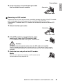
Attaching the legs.................................................................................................. 20
Installation in a rack............................................................................................... 20
Installation on a wall or ceiling............................................................................. 24
Settings................................................................................................................... 27
Make settings using the Web GUI .......................................................................... 27
Making settings from the command line using the CONSOLE port........................ 28
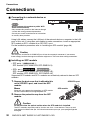
Connections ........................................................................................................... 30
Initialization ............................................................................................................ 34
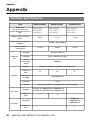
Appendix................................................................................................................. 36
Hardware specifications.......................................................................................... 36
Dimensional diagram.............................................................................................. 38
RJ-45/DB-9 console cable pin configuration........................................................... 39
Software license agreement ................................................................................... 40
Index........................................................................................................................ 42

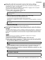
Introduction
10 SWR2310-28GT SWR2310-18GT SWR2310-10G
Introduction
Thank you for purchasing the Yamaha SWR2310-28GT, SWR2310-18GT, or SWR2310-10G
intelligent L2 switch.
This product is an intelligent L2 switch with optimal functionality for Dante. This owner’s
manual is intended for installers and facility designers, and explains installation methods and
settings. Please be sure to read this manual before you start using the product to take full
advantage of its features. Please retain this manual in a safe location for future reference.
Verify that the following included items are present.
• Owner’s manual (this document)
•Power cord
• Power cord clamp (used only for the included dedicated power cord)
• Legs (rubber feet) (4 pcs.)
• 19-inch rack mount hardware and screws (hardware: 2 pcs., screws: 8 pcs.)
/
These are required when installing this product in a 19-inch rack (1U size). For details on
installation, refer to “Installing in a 19-inch rack” / (page 23)
in “Installation.”
• This product makes it easy to specify the recommended settings for stable operation of a
Dante network (such as QoS, EEE, and IGMP Snooping).
• Multiple switches connected as a stack can be operated as a single virtual switch. The
SWR2310-28GT is equipped with stack functionality.
• This product can ease your daily network maintenance and operation responsibilities.
You can use Yamaha LAN Monitor (application) to ascertain the network structure that is
connected to this product and to monitor and manage the devices.
This product also supports performance management and damage management. All models
regularly monitor the memory and CPU usage and the bandwidth usage of each port. The
monitored data can be viewed in the Web GUI or backed-up to an SD card (sold separately).
The live/dead status of a network-connected terminal connected below this product can also
be monitored using only this product.
• This product can operate in cooperation with an authentication server to authenticate
terminals within the network.
This allows invalid terminals to be eliminated from the network.
Included items
Features
SWR2310-28GT
SWR2310-18GT
SWR2310-28GT
SWR2310-18GT

English
Introduction
SWR2310-28GT SWR2310-18GT SWR2310-10G
11
• RK-SWR rack mount accessory:
This is required when installing the SWR2310-10G in a 19-inch rack.
• WK-SWR wall mount accessory:
This is required when installing the SWR2310-10G or SWR2310-18GT on a wall or ceiling
2 m or less in height.
• SFP-SWRG-SX or SFP-SWRG-LX SPF module:
This is required when transmitting via 1000BASE-SX or 1000BASE-LX.
• SFP-SWRT-SR or SFP-SWRT-LR SFP+ module:
This is required when transmitting via 10GBASE-SR or 10GBASE-LR.
• DAC-SWRT-3M or DAC-SWRT-1M direct attach cable:
These are direct attach cables that provide SFP+ modules and copper cable in a single
unit. By directly connecting between SFP+ ports, these allow a 10 gigabit Ethernet system
to be constructed inexpensively, although with limited distance.
• Yamaha LAN Monitor/Yamaha LAN Monitor user guide
This is a PC application used to monitor this unit’s information and the entire network
including all Dante devices on the Dante network, and the user guide for this application.
• Yamaha network device USB serial driver / Yamaha network device USB serial driver
installation guide
This is a Windows driver that allows communication when the mini-USB CONSOLE port is
connected via a USB cable to a computer, and the installation guide for this driver.
• Command reference
This explains the commands used when using the command line to make settings from a
computer.
• Technical reference
This describes details of this product’s functions.
This software and these documents can be downloaded from the following website.
http://www.yamahaproaudio.com/
Separately sold items
Related software and documents

Controls and Connectors
12 SWR2310-28GT SWR2310-18GT SWR2310-10G
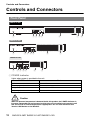
Controls and Connectors
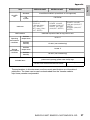
1 POWER indicator
Lights when power is provided to the unit.
Caution
When an abnormal temperature is detected inside this product, the POWER indicator is
lit orange. Reconsider the environment in which this unit is installed, and correctly install
this unit so that its internal temperature is appropriate. You can also check this from
Yamaha LAN Monitor or the Web GUI.
Front Panel
POWER indicator Status
Unlit Power off
Flashing (green) Power on, starting up
Lit (green) Power on, normal
Lit (orange) Power on, error occurred
SWR2310-28GT
2 4 6 8 10 12 14 16
26
1 3 5 7 9 11 13 15
18
17
20
19
22
21
24
23
25
28
27
1 23 45 6 7 8
2 4 6 8 10 12 14 16
18
1357 9111315
17
1 23 45 6 7
SWR2310-18GT
SWR2310-10G
2468
1357
10
9
1 23 45 6 9

English
Controls and Connectors
SWR2310-28GT SWR2310-18GT SWR2310-10G
13
2
mini-USB CONSOLE port
This is a mini-USB port for making settings. Use a USB cable to connect it to the USB port
of a computer. Use a USB cable equipped with a USB Type A connector and a USB mini-
B (5-pin) connector.
Memo
Use a cable that supports data transfer. Charge-only cables cannot be used.
3 RJ-45 CONSOLE port
This is an RJ-45 port for making settings. Use an RJ-45/DB-9 console cable to connect it
to the RS-232C connector (COM port) of the computer.
4 microSD indicator
Indicates the connection and usage status of the microSD card.
Caution
Do not remove the microSD card if this indicator is flashing green.
5 microSD slot
A microSD card can be inserted in this slot.
6 LAN ports
These ports support T10BASE-T, 100BASE-TX, and 1000BASE-T.
7 SFP+ ports /
These ports support T10GBASE-SR, 10GBASE-LR, 1000BASE-SX, and 1000BASE-LX.
Install an SFP+ module or SFP module sold separately by Yamaha. For the SWR2310-
28GT or SWR2310-18GT, install a direct attach cable (DAC-SWRT-3M or DAC-SWRT-1M).
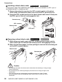
For details on installing an SFP+ or SFP module, refer to “Installing an SFP module”
(page 30) in “Connections.” For details on installing a direct attach cable, refer to “Installing
a direct attach cable” / (page 32). These ports can also
be used for stack connection. For details on stack connection, refer to "Making stack
connections” (page 33).
8 Stack ID indicator
This is a 7-segment display that indicates the stack ID when stack connection is used.
9 SFP ports
These ports support 1000BASE-SX and 1000BASE-LX. Install an SFP module sold
separately by Yamaha.
For details on installing an SFP module, refer to “Installing an SFP module” (page 30) in
“Connections.”
microSD indicator Status
Unlit A microSD card is not inserted in the slot.
Flashing green The microSD card is being accessed.
Lit green A microSD card is inserted.
SWR2310-28GT
SWR2310-18GT
SWR2310-28GT
SWR2310-18GT
SWR2310-28GT
SWR2310-28GT
SWR2310-10G

Controls and Connectors
14 SWR2310-28GT SWR2310-18GT SWR2310-10G
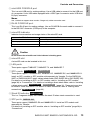
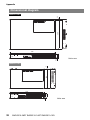
° Bottom panel
Bottom panel / rear panel / side panel / top panel
SWR2310-28GT
0
SWR2310-18GT
0 B

English
Controls and Connectors
SWR2310-28GT SWR2310-18GT SWR2310-10G
15
0
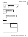
Leg attachment guides
These indicate the locations at which the included legs are to be attached when the unit is
installed in a level location. For details on installation, refer to “Attaching the legs”
(page 20) in “Installation.”
A Rack mount accessory attachment holes
Use these holes to attach the RK-SWR rack mount accessory. For details on installation,
refer to “Installing in a 19-inch rack” (page 21) in “Installation.”
B Wall mount accessory attachment holes /
Use these holes to attach the WK-SWR wall mount accessory.
For details on installation, refer to “Installation on a wall or ceiling” /
(page 24).
Notice
Magnet sheets are not supported, and should not be used.
SWR2310-10G
0 A
B
SWR2310-10G
SWR2310-10G
SWR2310-18GT
SWR2310-10G
SWR2310-18GT
SWR2310-10G

Controls and Connectors
16 SWR2310-28GT SWR2310-18GT SWR2310-10G
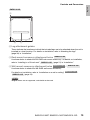
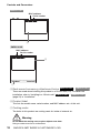
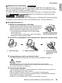
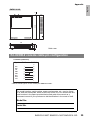
° Rear panel
C Power cord clamp attachment holes
The included power cord clamp (C-shaped) can be attached here. For details on
installation, refer to “Turning the power on” (page 33) in “Connections.”
D Power supply inlet (three-pin connector, C14 type)
Insert the included power supply cord here.
SWR2310-28GT
D
C
Serial number
SWR2310-18GT
D
C
Serial number
SWR2310-10G
D
C
Serial number

English
Controls and Connectors
SWR2310-28GT SWR2310-18GT SWR2310-10G
17
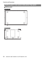
° Side panel
° Top panel
SWR2310-28GT
E G
SWR2310-18GT
E G
SWR2310-10G
G
SWR2310-28GT
F
Serial number
MAC address

Controls and Connectors
18 SWR2310-28GT SWR2310-18GT SWR2310-10G
E Rack mount accessory attachment holes /
These are used when installing this product in a 19-inch rack (1U). For details on
installation, refer to “Installing in a 19-inch rack” /
(page 23) in “Installation.”
F Product label
This lists the model name, serial number, and MAC address etc. of this unit.
G Cooling vents
The holes in this product are cooling vents for intake of external air.
Warning
Do not block the cooling vents or place objects near them.
Doing so could cause fire or malfunctions.
SWR2310-18GT
F
Serial number
MAC address
SWR2310-10G
F
G
Serial number
MAC address
SWR2310-28GT
SWR2310-18GT
SWR2310-28GT
SWR2310-18GT

English
Controls and Connectors
SWR2310-28GT SWR2310-18GT SWR2310-10G
19
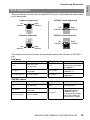
These are indicators for the LAN ports and SFP/SFP+ ports, and indicate the state of each
port in each mode.
The indicators show the link status and connection speed of the LAN port or SFP/SFP+
port.
LAN ports
SFP/SFP+ ports
Port indicators
Left indicator Link status Right indicator Connection speed
Unlit
The link is lost.
(unavailable)
Unlit
Not connected.
Alternatively, connected
by 10BASE-T.
Lit (green)
A link is established.
(available)
Lit (orange)
Connected by
100BASE-TX.
Flashing (green) Data is flowing. Lit (green)
Connected by
1000BASE-T.
Left indicator Link status Right indicator Connection speed
Unlit
The link is lost.
(unavailable)
Unlit Not connected.
Lit (green)
A link is established.
(available)
Lit (green)
Connected by
1000BASE-SX/LX or
10GBASE-SR/LR.
If using the DAC-SWRT-
3M or DAC-SWRT-1M,
connected at 10 Gbps.
Flashing (green) Data is flowing.
Left
Indicator
LAN ports (upper row)
LAN ports (lower row) SFP/SFP+ ports (lower row)
SFP/SFP+ ports (upper row)
Left
Indicator
Left
Indicator
Left
Indicator
Right
Indicator
Right
Indicator
Right
Indicator
Right
Indicator

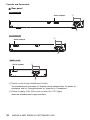
Attaching the legs
20 SWR2310-28GT SWR2310-18GT SWR2310-10G
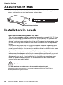
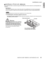
Attaching the legs
As shown in the illustration, attach the included legs in the positions of the leg attachment
guides, and place the unit on a level location such as a desk.
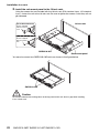
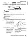
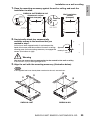
Installation in a rack
Please read before mounting the unit into a rack
• This unit is warrantied to operate in an ambient temperature range of 0–50 °C. If you
install this unit along with other devices into an EIA-standard or JIS-standard rack,
the temperature inside the rack may rise due to heat released from the other
devices, resulting in poor performance of the unit. To prevent the temperature inside
the unit from rising, mount the unit in the rack in accordance with the requirements
below.
• If you plan to rack-mount the unit along with a device that tends to generate heat,
such as an amplifier (excluding an XMV series), be sure to leave a gap of 1U or
more from such devices. Also, be sure to maintain sufficient ventilation in this space
by installing a ventilation panel or leaving it open.
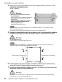
• Open the rear panel of the rack, and place the rack at least 10cm (about four
inches) away from the walls and ceiling to ensure sufficient ventilation. If you cannot
open the rear panel of the rack, install a commercially-available forced ventilation
device, such as a fan kit. If you install a fan kit, closing the rear panel may work
better for heat dissipation purposes. For more information, refer to the owner’s
manual for the rack and/or fan kit.
Caution
If you plan to relocate the rack, be sure to first remove this unit from the rack.
If you move the unit while it is still installed in the rack, vibration or physical shock might deform
or damage the rack mount accessory or rack mount hardware, causing injury. There is also a
possibility that this unit might malfunction.
2 4 6 8 10 12 14 16
26
1357911 1315
18
17
20
19
22
21
24
23
25
28
27
Leg
Leg
Leg attachment guides
Seite wird geladen ...
Seite wird geladen ...
Seite wird geladen ...
Seite wird geladen ...
Seite wird geladen ...
Seite wird geladen ...
Seite wird geladen ...
Seite wird geladen ...
Seite wird geladen ...
Seite wird geladen ...
Seite wird geladen ...
Seite wird geladen ...
Seite wird geladen ...
Seite wird geladen ...
Seite wird geladen ...
Seite wird geladen ...
Seite wird geladen ...
Seite wird geladen ...
Seite wird geladen ...
Seite wird geladen ...
Seite wird geladen ...
Seite wird geladen ...
Seite wird geladen ...
Seite wird geladen ...
Seite wird geladen ...
Seite wird geladen ...
Seite wird geladen ...
Seite wird geladen ...
Seite wird geladen ...
Seite wird geladen ...
-
 1
1
-
 2
2
-
 3
3
-
 4
4
-
 5
5
-
 6
6
-
 7
7
-
 8
8
-
 9
9
-
 10
10
-
 11
11
-
 12
12
-
 13
13
-
 14
14
-
 15
15
-
 16
16
-
 17
17
-
 18
18
-
 19
19
-
 20
20
-
 21
21
-
 22
22
-
 23
23
-
 24
24
-
 25
25
-
 26
26
-
 27
27
-
 28
28
-
 29
29
-
 30
30
-
 31
31
-
 32
32
-
 33
33
-
 34
34
-
 35
35
-
 36
36
-
 37
37
-
 38
38
-
 39
39
-
 40
40
-
 41
41
-
 42
42
-
 43
43
-
 44
44
-
 45
45
-
 46
46
-
 47
47
-
 48
48
-
 49
49
-
 50
50


Yamaha SWR2310 Bedienungsanleitung
- Kategorie
- Vernetzung
- Typ
- Bedienungsanleitung
in anderen Sprachen
- English: Yamaha SWR2310 Owner's manual
- français: Yamaha SWR2310 Le manuel du propriétaire
- español: Yamaha SWR2310 El manual del propietario
- italiano: Yamaha SWR2310 Manuale del proprietario
- Nederlands: Yamaha SWR2310 de handleiding
- português: Yamaha SWR2310 Manual do proprietário
- dansk: Yamaha SWR2310 Brugervejledning
- polski: Yamaha SWR2310 Instrukcja obsługi
- čeština: Yamaha SWR2310 Návod k obsluze
- română: Yamaha SWR2310 Manualul proprietarului
Verwandte Artikel
Andere Dokumente
-
Sony CMA-D2 Bedienungsanleitung
-
Harmonic ProView 7000 3.5 Installationsanleitung
-
-
AJA IPR-10G2-SDI Benutzerhandbuch
-
Dell PowerSwitch N3000 Series Benutzerhandbuch
-
-
-
-
-
Parker 10G-11-0045 Series Benutzerhandbuch