Yamaha RSio64 Bedienungsanleitung
- Kategorie
- Zusätzliche Musikausrüstung
- Typ
- Bedienungsanleitung

I/O RACK
Owner’s Manual
AUDIO INTERFACE
Bedienungsanleitung
Mode d’emploi
Manual de instrucciones
Manuale di istruzioni
Руководство пользователя
Manual do Proprietário
JA
PT
RU
IT
ES
FR
DE
EN
EnglishDeutschFrançaisEspañolItalianoРусскийPortuguês

2
Owner’s Manual
The above warning is located on the top of the unit.
L’avertissement ci-dessus est situé sur le dessus de l’unité.
Explanation of Graphical Symbols
Explication des symboles
The lightning flash with arrowhead symbol within an equilateral triangle is intended to alert the user to the presence of uninsulated “danger-
ous voltage” within the product’s enclosure that may be of sufficient magnitude to constitute a risk of electric shock to persons.
L’éclair avec une flèche à l’intérieur d’un triangle équilatéral est destiné à attirer l’attention de l’utilisateur sur la présence d’une « tension
dangereuse » non isolée à l’intérieur de l’appareil, pouvant être suffisamment élevée pour constituer un risque d’électrocution.
The exclamation point within an equilateral triangle is intended to alert the user to the presence of important operating and maintenance (ser-
vicing) instructions in the literature accompanying the product.
Le point d’exclamation à l’intérieur d’un triangle équilatéral est destiné à attirer l’attention de l’utilisateur sur la présence d’instructions
importantes sur l’emploi ou la maintenance (réparation) de l’appareil dans la documentation fournie.
IMPORTANT SAFETY
INSTRUCTIONS
1 Read these instructions.
2 Keep these instructions.
3 Heed all warnings.
4 Follow all instructions.
5 Do not use this apparatus near water.
6 Clean only with dry cloth.
7 Do not block any ventilation openings. Install in accordance with the
manufacturer’s instructions.
8 Do not install near any heat sources such as radiators, heat registers,
stoves, or other apparatus (including amplifiers) that produce heat.
9 Do not defeat the safety purpose of the polarized or grounding-type
plug. A polarized plug has two blades with one wider than the other. A
grounding type plug has two blades and a third grounding prong. The
wide blade or the third prong are provided for your safety. If the pro-
vided plug does not fit into your outlet, consult an electrician for
replacement of the obsolete outlet.
10 Protect the power cord from being walked on or pinched particularly at
plugs, convenience receptacles, and the point where they exit from the
apparatus.
11 Only use attachments/accessories specified by the manufacturer.
12 Use only with the cart, stand, tripod, bracket, or
table specified by the manufacturer, or sold with
the apparatus. When a cart is used, use caution
when moving the cart/apparatus combination to
avoid injury from tip-over.
13 Unplug this apparatus during lightning storms or
when unused for long periods of time.
14 Refer all servicing to qualified service personnel. Servicing is required
when the apparatus has been damaged in any way, such as power-
supply cord or plug is damaged, liquid has been spilled or objects
have fallen into the apparatus, the apparatus has been exposed to rain
or moisture, does not operate normally, or has been dropped.
(UL60065_03)
PRÉCAUTIONS CONCER-
NANT LA SÉCURITÉ
1 Lire ces instructions.
2 Conserver ces instructions.
3 Tenir compte de tous les avertissements.
4 Suivre toutes les instructions.
5 Ne pas utiliser ce produit à proximité d’eau.
6 Nettoyer uniquement avec un chiffon propre et sec.
7 Ne pas bloquer les orifices de ventilation. Installer l’appareil confor-
mément aux instructions du fabricant.
8 Ne pas installer l’appareil à proximité d’une source de chaleur comme
un radiateur, une bouche de chaleur, un poêle ou tout autre appareil (y
compris un amplificateur) produisant de la chaleur.
9 Ne pas modifier le système de sécurité de la fiche polarisée ou de la
fiche de terre. Une fiche polarisée dispose de deux broches dont une
est plus large que l’autre. Une fiche de terre dispose de deux broches
et d’une troisième pour le raccordement à la terre. Cette broche plus
large ou cette troisième broche est destinée à assurer la sécurité de
l’utilisateur. Si la fiche équipant l’appareil n’est pas compatible avec
les prises de courant disponibles, faire remplacer les prises par un
électricien.
10 Acheminer les cordons d’alimentation de sorte qu’ils ne soient pas
piétinés ni coincés, en faisant tout spécialement attention aux fiches,
prises de courant et au point de sortie de l’appareil.
11 Utiliser exclusivement les fixations et accessoires spécifiés par le
fabricant.
12 Utiliser exclusivement le chariot, le stand, le tré-
pied, le support ou la table recommandés par le
fabricant ou vendus avec cet appareil. Si l’appa-
reil est posé sur un chariot, déplacer le chariot
avec précaution pour éviter tout risque de chute
et de blessure.
13 Débrancher l’appareil en cas d’orage ou lorsqu’il
doit rester hors service pendant une période prolongée.
14 Confier toute réparation à un personnel qualifié. Faire réparer l’appa-
reil s’il a subi tout dommage, par exemple si la fiche ou le cordon d’ali-
mentation est endommagé, si du liquide a coulé ou des objets sont
tombés à l’intérieur de l’appareil, si l’appareil a été exposé à la pluie ou
à de l’humidité, si l’appareil ne fonctionne pas normalement ou est
tombé.
(UL60065_03)
WARNING
TO REDUCE THE RISK OF FIRE OR ELECTRIC SHOCK, DO NOT
EXPOSE THIS APPARATUS TO RAIN OR MOISTURE.
AVERTISSEMENT
POUR RÉDUIRE LES RISQUES D’INCENDIE OU DE DÉCHARGE ÉLEC-
TRIQUE, N’EXPOSEZ PAS CET APPAREIL À LA PLUIE OU À L’HUMIDITÉ.

Owner’s Manual
3
이 기기는 가정용(B급) 전자파적합기기로서 주로 가정에서 사용하는 것을 목적으로
하며, 모든 지역에서 사용할 수 있습니다.
(class b korea)
1. IMPORTANT NOTICE: DO NOT MODIFY THIS UNIT!
This product, when installed as indicated in the instructions con-
tained in this manual, meets FCC requirements. Modifications
not expressly approved by Yamaha may void your authority,
granted by the FCC, to use the product.
2. IMPORTANT: When connecting this product to accessories
and/or another product use only high quality shielded cables.
Cable/s supplied with this product MUST be used. Follow all
installation instructions. Failure to follow instructions could void
your FCC authorization to use this product in the USA.
3. NOTE: This product has been tested and found to comply with
the requirements listed in FCC Regulations, Part 15 for Class “B”
digital devices. Compliance with these requirements provides a
reasonable level of assurance that your use of this product in a
residential environment will not result in harmful interference with
other electronic devices. This equipment generates/uses radio
frequencies and, if not installed and used according to the
instructions found in the users manual, may cause interference
harmful to the operation of other electronic devices. Compliance
with FCC regulations does not guarantee that interference will
not occur in all installations. If this product is found to be the
source of interference, which can be determined by tur
ning the
unit “OFF” and “ON”, please try to eliminate the problem by using
one of the following measures:
Relocate either this product or the device that is being affected
by the interference.
Utilize power outlets that are on different branch (circuit breaker
or fuse) circuits or install AC line filter/s.
In the case of radio or TV interference, relocate/reorient the
antenna. If the antenna lead-in is 300 ohm ribbon lead, change
the lead-in to co-axial type cable.
If these corrective measures do not produce satisfactory results,
please contact the local retailer authorized to distribute this type
of product. If you can not locate the appropriate retailer, please
contact Yamaha Corporation of America, Electronic Service Divi-
sion, 6600 Orangethorpe Ave, Buena Park, CA90620
The above statements apply ONLY to those products distributed
by Yamaha Corporation of America or its subsidiaries.
* This applies only to products distributed by YAMAHA CORPORATION OF AMERICA. (class B)
FCC INFORMATION (U.S.A.)
COMPLIANCE INFORMATION STATEMENT
(DECLARATION OF CONFORMITY PROCEDURE)
Responsible Party : Yamaha Corporation of America
Address : 6600 Orangethorpe Ave., Buena Park, Calif. 90620
Telephone : 714-522-9011
Type of Equipment : Audio Interface
Model Name : RSio64-D
This device complies with Part 15 of the FCC Rules.
Operation is subject to the following two conditions:
1) this device may not cause harmful interference, and
2) this device must accept any interference received including interference that may
cause undesired operation.
See user manual instructions if interference to radio reception is suspected.
* This applies only to products distributed by YAMAHA CORPORATION OF AMERICA. (FCC DoC)
IMPORTANT NOTICE FOR THE UNITED KINGDOM
Connecting the Plug and Cord
WARNING: THIS APPARATUS MUST BE EARTHED IMPORTANT. The wires in this
mains lead are coloured in accordance with the following code:
GREEN-AND-YELLOW : EARTH
BLUE : NEUTRAL
BROWN : LIVE
As the colours of the wires in the mains lead of this apparatus may not correspond with
the coloured markings identifying the terminals in your plug proceed as follows:
The wire which is coloured GREEN-and-YELLOW must be connected to the terminal in
the plug which is marked by the letter E or by the safety earth symbol or colored
GREEN or GREEN-and-YELLOW.
The wire which is coloured BLUE must be connected to the terminal which is marked
with the letter N or coloured BLACK.
The wire which is coloured BROWN must be connected to the terminal which is
marked with the letter L or coloured RED.
(3 wires)
In Finland: Laite on liitettävä suojamaadoituskoskettimilla varustettuun pistorasiaan.
In Norway: Apparatet må tilkoples jordet stikkontakt.
In Sweden: Apparaten skall anslutas till jordat uttag.
(class I hokuo)

4
Owner’s Manual
Contents
PRECAUTIONS. . . . . . . . . . . . . . . . . . .5
Introduction 8
Features....................................................... 8
Precautions for Rack Mounting .................... 8
Firmware Updates........................................ 8
Controls and Functions 9
Front Panel .................................................. 9
Rear Panel.................................................. 12
Connections 14
Installing a Mini-YGDAI card ...................... 14
About Dante.............................................. 14
Notes Regarding the Use of
Network Switches ................................. 15
About Dante Controller ............................. 15
Connecting AC Power................................ 15
Power on and off ....................................... 15
Specifying the audio routing 16
Editing the user pattern ............................. 17
About R Remote V4 ................................... 17
About the number of
input/output channels........................... 17
Word Clock 18
Selecting a word clock source .................... 18
About word clock ...................................... 18
SRC (Sampling Rate Converter). . . .18
Other functions 19
Remote control.......................................... 19
IDENTIFY ................................................... 19
Panel lock .................................................. 19
Initializing the RSio64-D............................. 20
Updating the RSio64-D’s
hardware settings.................................. 20
If you are using the card’s SRC................... 20
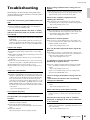
Troubleshooting . . . . . . . . . . . . . . . 21
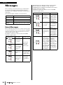
Messages 22
Error Messages........................................... 22
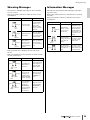
Warning Messages ..................................... 23
Information Messages ................................ 23
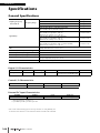
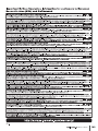
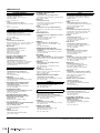
Specifications . . . . . . . . . . . . . . . . 166
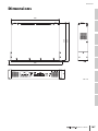
Dimensions . . . . . . . . . . . . . . . . . . 167
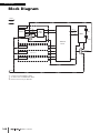
Block Diagram . . . . . . . . . . . . . . . 168
Various settings
Specifying the RSio64-D’s word clock...........18
Specifying the audio routing ........................16
Specifying the ID that
distinguishes the RSio64-D ......................10
Specifying the UNIT ID range .......................10
Specifying how the IP address is set..............10
Specifying the type of
connection to the Dante network ............11
Initializing the RSio64-D ...............................20
Specifying the SRC word clock .....................11
Included items (please check)
•Owner’s manual
•Power cord

Owner’s Manual
5
PRECAUTIONS
PLEASE READ CAREFULLY
BEFORE PROCEEDING
Please keep this manual in a safe place for
future reference.
WARNING
Always follow the basic precautions listed below to
avoid the possibility of serious injury or even death
from electrical shock, short-circuiting, damages, fire
or other hazards. These precautions include, but are
not limited to, the following:
Power supply/power cord
• Do not place the power cord near heat sources such as
heaters or radiators, and do not excessively bend or
otherwise damage the cord, place heavy objects on it, or
place it in a position where anyone could walk on, trip over,
or roll anything over it.
• Only use the voltage specified as correct for the device.
The required voltage is printed on the name plate of the
device.
• Use only the supplied power cord/plug.
If you intend to use the device in an area other than in the
one you purchased, the included power cord may not be
compatible. Please check with your Yamaha dealer.
• Check the electric plug periodically and remove any dirt or
dust which may have accumulated on it.
• When setting up the device, make sure that the AC outlet
you are using is easily accessible. If you feel that a
malfunction has occurred, immediately turn off the power,
unplug the power cord plug from the electrical outlet, and
also disconnect the connected power supply from the EXT
DC INPUT jack. Even when the power switch is turned off,
as long as the power cord is not unplugged from the wall
AC outlet, the device will not be disconnected from the
power source.
• Be sure to connect to an appropriate outlet with a
protective grounding connection. Improper grounding can
result in electrical shock, damage to the device(s), or even
fire.
Do not open
• This device contains no user-serviceable parts. Do not
open the device or attempt to disassemble the internal
parts or modify them in any way. If it should appear to be
malfunctioning, discontinue use immediately and have it
inspected by qualified Yamaha service personnel.
Water warning
• Do not expose the device to rain, use it near water or in
damp or wet conditions, or place on it any containers (such
as vases, bottles or glasses) containing liquids which might
spill into any openings. If any liquid such as water seeps
into the device, turn off the power immediately and unplug
the power cord from the AC outlet. Then have the device
inspected by qualified Yamaha service personnel.
• Never insert or remove an electric plug with wet hands.
Fire warning
• Do not put burning items, such as candles, on the unit.
A burning item may fall over and cause a fire.
If you notice any abnormality
• When one of the following problems occur, immediately
turn off the power switch and disconnect the electric plug
from the outlet. Then have the device inspected by Yamaha
service personnel.
- The power cord or plug becomes frayed or damaged.
- It emits unusual smells or smoke.
- Some object has been dropped into the device.
- There is a sudden loss of sound during use of the device.
• If this device should be dropped or damaged, immediately
turn off the power switch, disconnect the electric plug from
the outlet, and have the device inspected by qualified
Yamaha service personnel.
CAUTION
Always follow the basic precautions listed below to
avoid the possibility of physical injury to you or
others, or damage to the device or other property.
These precautions include, but are not limited to, the
following:
Power supply/power cord
• When removing the electric plug from the device or an
outlet, always hold the plug itself and not the cord. Pulling
by the cord can damage it.
• Remove the electric plug from the outlet when the device is
not to be used for extended periods of time, or during
electrical storms.
Location
• Do not place the device in an unstable position where it
might accidentally fall over.
• Do not block the vents. This device has ventilation holes at
the front/sides to prevent the internal temperature from
becoming too high. In particular, do not place the device
on its side or upside down. Inadequate ventilation can
result in overheating, possibly causing damage to the
device(s), or even fire.
• When installing the device:
- Do not cover it with any cloth.
- Do not install it on a carpet or rug.
- Make sure the top surface faces up; do not install on its
sides or upside down.
- Do not use the device in a confined, poorly-ventilated
location.
Inadequate ventilation can result in overheating, possibly
causing damage to the device(s), or even fire.
• Do not place the device in a location where it may come
into contact with corrosive gases or salt air. Doing so may
result in malfunction.
• Before moving the device, remove all connected cables.
PA_en_4 1/2

6
Owner’s Manual
• When setting up the device, make sure that the AC outlet
you are using is easily accessible. If some trouble or
malfunction occurs, immediately turn off the power switch
also disconnect the unit from the power supply that is
connected to the EXT DC INPUT jack. Even when the
power switch is turned off, electricity is still flowing to the
product at the minimum level. When you are not using the
product for a long time, make sure to unplug the power
cord from the wall AC outlet.
• If the device is mounted in an EIA standard rack, carefully
read the section “Precautions for Rack Mounting” on page
8. Inadequate ventilation can result in overheating,
possibly causing damage to the device(s), malfunction, or
even fire.
Connections
• Before connecting the device to other devices, turn off the
power for all devices. Before turning the power on or off for
all devices, set all volume levels to minimum.
Maintenance
• Periodically inspect and clean the air filter of the front panel
ventilation opening (page 11). Dust and dirt can seriously
degrade the effectiveness of the cooling fan and result in
malfunction or fire.
• Remove the power plug from the AC outlet when cleaning
the device.
Handling caution
• Do not insert your fingers or hands in any gaps or openings
on the device (vents).
• Avoid inserting or dropping foreign objects (paper, plastic,
metal, etc.) into any gaps or openings on the device (vents,
etc.) If this happens, turn off the power immediately and
unplug the power cord from the AC outlet. Then have the
device inspected by qualified Yamaha service personnel.
• Do not rest your weight on the device or place heavy
objects on it, and avoid use excessive force on the buttons,
switches or connectors.
NOTICE
To avoid the possibility of malfunction/ damage to the product,
damage to data, or damage to other property, follow the
notices below.
Handling and maintenance
• Do not use the device in the vicinity of a TV, radio, stereo
equipment, mobile phone, or other electric devices. Other-
wise, the device, TV, or radio may generate noise.
• Do not expose the device to excessive dust or vibration, or
extreme cold or heat (such as in direct sunlight, near a
heater, or in a car during the day), in order to prevent the
possibility of panel disfiguration, unstable operation, or
damage to the internal components.
• Do not place vinyl, plastic or rubber objects on the device,
since this might discolor the panel.
• When cleaning the device, use a dry and soft cloth. Do not
use paint thinners, solvents, cleaning fluids, or chemical-
impregnated wiping cloths.
• Condensation can occur in the device due to rapid, drastic
changes in ambient temperature—when the device is
moved from one location to another, or air conditioning is
turned on or off, for example. Using the device while con-
densation is present can cau
se damage. If there is reason
to
believe that condensation might have occurred, leave
the device for several hours without turning on the power
until the condensation has completely dried out.
•Always turn the power off when the device is not in use.
Information
About this manual
• The illustrations as shown in this manual are for instruc-
tional purposes only.
• The company names and product names in this manual
are the trademarks or registered trademarks of their
respective companies.
Yamaha cannot be held responsible for damage caused
by improper use or modifications to the device, or data
that is lost or destroyed.
PA_en_4 2/2

Owner’s Manual
7
(weee_eu_en_01)
European Models
Purchaser/User Information specified in EN55103-1:2009 and EN55103-2:2009.
Inrush Current: 1.0A (on initial switch-on)
1.0A (after a supply interruption of 5s)
Conforms to Environments: E1, E2, E3 and E4
Information for Users on Collection and Disposal of Old Equipment
This symbol on the products, packaging, and/or accompanying documents means that used electrical
and electronic products should not be mixed with general household waste.
For proper treatment, recovery and recycling of old products, please take them to applicable collection
points, in accordance with your national legislation and the Directives 2002/96/EC.
By disposing of these products correctly, you will help to save valuable resources and prevent any poten-
tial negative effects on human health and the environment which could otherwise arise from inappropri-
ate waste handling.
For more information about collection and recycling of old products, please contact your local municipal-
ity, your waste disposal service or the point of sale where you purchased the items.
[For business users in the European Union]
If you wish to discard electrical and electronic equip
ment, please contact your dealer or supplier for fur-
ther information.
[Information on Disposal in other Countries outside the European Union]
This symbol is only valid in the European Union. If you wish to discard these items, please contact your
local authorities or dealer and ask for the correct method of disposal.
The model number, serial number, power requirements, etc., may be found on or
near the name plate, which is at the top of the unit. You should note this serial
number in the space provided below and retain this manual as a permanent
record of your purchase to aid identification in the event of theft.
Model No.
Serial No.
(rear_en_01)

8
Owner’s Manual
Introduction
Introduction
Thank you for choosing the Yamaha RSio64-D audio
interface.
To take full advantage of the superior functions and
performance offered by the RSio64-D, and to enjoy years of
trouble-free use, be sure to read this owner’s manual
carefully before operation.
Features
The RSio64-D is an interface that can be used as a router
and format converter between Dante and Mini-YGDAI
cards.
This allows Mini-YGDAI cards that support a wide variety
of input/output formats and processing to be connected to
a Dante network, meeting the needs of various types of
systems including broadcast, live, recording, and post-
production. In addition, the settings of the RSio64-D can
be fully controlled from a CL or QL series console.
• A wide variety of Mini-YGDAI cards can be used,
including processing cards as well as input/output cards.
• Each MY slot provides an SRC (Sampling Rate
Converter) to allow digital connection between differing
word clock routes.
• Seven different widely usable routing patterns are preset,
including routing between Mini-YGDAI cards. Matrix
patching from R Remote V4 or a CL/QL console.
• EXT DC INPUT supports redundant power supplies.
• Dante redundancy (primary/secondary) is supported.
NOTE
Before you install Mini-YGDAI cards in slots 1–4, you must
check the Yamaha website to determine whether the card is
compatible with the RSio64-D, and to verify the total number
of Yamaha or third-party cards that can be installed in
combination with that card.
Yamaha website:
http://www.yamahaproaudio.com/
Precautions for Rack
Mounting
This unit is rated for operation at ambient temperatures
ranging from 0 to 40 degrees Celsius. When mounting the
unit with other RSio unit(s) or other device(s) in an EIA
standard equipment rack, internal temperatures can
exceed the specified upper limit, resulting in impaired
performance or failure. When rack mounting the unit,
always observe the following requirements to avoid heat
buildup:
• When mounting the unit in a rack with devices such as
power amplifiers that generate a significant amount of
heat, leave more than 1U of space between the RSio and
other equipment. Also either leave the open spaces
uncovered or install appropriate ventilating panels to
minimize the possibility of heat buildup.
• To ensure sufficient airflow, leave the rear of the rack
open and position it at least 10 centimeters from walls or
other surfaces. If you’ve installed a fan kit, there may be
cases in which closing the rear of the rack will produce a
greater cooling effect. Refer to the rack and/or fan unit
manual for details.
Firmware Updates
This product enables you to update the unit firmware to
improve operations, add functions, and correct possible
malfunctions. The following two types of firmware are
available for the unit:
•Unit’s firmware
•Dante module firmware
Firmware updates are performed from R Remote V4.
Details on updating the firmware are available on the
following website:
http://www.yamahaproaudio.com/
For information on updating the unit, refer to the firmware
update guide available on the website.
NOTE
It is necessary to update other devices depending on the
version of each device in the Dante network. For details,
refer to the firmware compatibility available on the Yamaha
website.
http://www.yamahaproaudio.com/

Owner’s Manual
9
Controls and Functions
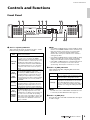
Controls and Functions
Front Panel
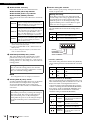
q SLOT 1–4 [LOCK] indicators
These indicate the word clock status of slots 1–4. The
indicator is lit green if operation is normal.
NOTE
• If the SLOT1–4 [LOCK] indicators and the SLOT1–4 [SRC]
indicators and all WORD CLOCK indicators simultaneously
flash red at startup, overcurrent has occurred in a Mini-
YGDAI card, or a malfunctioning Mini-YGDAI card is
installed. Turn off the power and remove the card that is
causing the problem.
• If the SLOT1–4 [LOCK] indicators and the SLOT1–4 [SRC]
indicators alternately flash red at startup, the hardware
settings of the RSio64-D need to be updated (page 20).
• If the SLOT1–4 [LOCK] indicators sequentially light green in
the order of 1–4 at startup, the clocks of the slots are
synchronizing. This may take several tens of seconds.
w SLOT 1–4 [SRC] indicators
These indicate the SRC (Sampling Rate Converter)
status of slots 1–4.
NOTE
The SRC clock sent to a Mini-YGDAI card installed in a slot
is selected by the SRC WCLK DIP switch (page 11).
e SLOT 1–4 [SRC] keys
For each slot, these turn SRC on/off for the slot’s input
as well as output.
ON
12345678
ON
1234
o!0r!3 tyq!3
we u i !1 !2
Unlit
No card is installed in the slot, or an unsup-
ported card is installed.
Green (lit)
LOCK
This indicates that a clock synchronized with
the clock source selected by the WORD
CLOCK select key is being input from the card.
If an external device is connected to the corre-
sponding slot, input/output is occurring cor-
rectly between that device and the RSio64-D.
If the sampling frequency is close, this status
is shown in some cases even if not synchro-
nized.
Green
(flashing)
SYNC
ERROR
A valid clock is being input from the card, but is
not synchronized with the clock source
selected by the WORD CLOCK select key. If
an external device is connected to the corre-
sponding slot, input/output is not occurring
correctly between that device and the RSio64-
D. Input/output will occ
ur c
orrectly if SRC is
turned ON.
Red (lit)
UNLOCK
A valid clock is not being input from the card. If
an external device is connected to the corre-
sponding slot, input/output cannot occur cor-
rectly between that device and the RSio64-D.
Red
(flashing)
WRONG
WORD
CLOCK
The frequency of the clock source selected by
the WORD CLOCK select key is outside the
range of operating frequencies of the card
installed in the slot. Either set the frequency of
the clock source to be within the operating
range of the card, or turn SRC on. In the case
of an analog card, turning SRC on makes the
card operate at the RSio64-D’s internal fre-
quency of 48 kHz.
Unlit SRC is off.
Green (lit)
SRC is on, and the clock selected by the SRC
WCLK DIP switch is being input correctly.
Red (lit)
SRC is on, but an appropriate clock is not
being input. It may be that the clock selected
by the SRC WCLK DIP switch is not being
input, or is outside the operating range. Either
turn SRC off, or change the setting of the DIP
switch.

10
Owner’s Manual
Controls and Functions
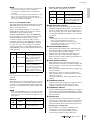
r WORD CLOCK select key
Selects the word clock source of the RSio64-D.
WORD CLOCK [WCLK IN] indicator
WORD CLOCK [SLOT1 1/2] indicator
WORD CLOCK [DANTE] indicator
These indicate the status of the RSio64-D’s word clock
source.
*1 When this is flashing, the unit uses the Dante word clock to
operate and perform input/output.
*2 In order to use MY8-AEB, set AE RSVD switch to the
RSVD position.
*3 If you want to change the frequency of the Dante word
clock, use Dante Controller.
t ROUTING [PATTERN] rotary switch
This selects the RSio64-D’s internal audio routing
pattern from seven preset patterns and one user
pattern. Setting the rotary switch to 1–7 selects preset
routing patterns 1–7, and setting it to 0 selects the user
routing pattern.
NOTE
The routing pattern does not change if you select 8–F.
y SETUP [UNIT ID] rotary switch
Specifies an ID that identifies this device on the Dante
network. If there are multiple Dante-compatible
devices from Yamaha that require an ID setting
connected to the same network, set a different ID for
each device.
u Device setting DIP switches
These switches specify startup settings for the device.
Details are given below.
The switch illustrations indicate the setting state as
follows.
•Switch 1 (UNIT ID)
This switch setting determines whether the [UNIT ID]
setting will range from hexadecimal 00 to 0F or from 10
to 1F.
• Switch 2/Switch 3 (IP SETTING)
These specify the method of setting the IP address used
when communicating with an external device such as R
Remote V4. When connecting the RSio64-D to a
computer for the first time immediately after purchase,
set this to something other than STATIC IP (MANUAL).
If you want to set this to STATIC IP (MANUAL), first
specify the IP address from R Remote V4 and then
switch this setting to STATIC IP (MANUAL).
WCLK IN
This is lit if the RSio64-D is using the word
clock that is being input from the rear panel
[WORD CLOCK IN] connector. This flashes if
there is no valid word clock input
*1
.
SLOT1 1/2
This is lit if the channel 1/2 word clock of slot 1
is being used. This flashes if there is no valid
word clock input
*1
. The channel 7/8 word clock
is used when using the MY8-AEB
*2
. If the
SRC on the MY8-AE96S is in use, you will be
unable to use the input signal as word clock.
DANTE
This is lit if the Dante network’s word clock
*3
is being used. (If no valid Dante signal is being
input, the clock generated by the internal
Dante module is used.)
Making the setting
You can select the routing pattern even when the
power is on. Your selection is applied three seconds
after you switch the routing pattern.
Making the setting
Turn off the power before you change the setting of
this rotary switch. The setting is applied the next
time you turn the power on. If you change the
setting while the power is on, the changed setting is
not applied until the power is turned off and on
again.
Making the setting
Turn off the power before you change these DIP
switch settings. The setting is applied the next time
you turn the power on. If you change the setting
while the power is on, the changed setting is not
applied until the power is turned off and on again.
(This note does not apply to switch 6.)
Switch State
Switch is in the upward (OFF) position.
Switch is in the downward (ON) position.
Switch Setting Description
UNIT ID =
00-0F
The UNIT ID setting range is 00
to 0F.
UNIT ID =
10-1F
The UNIT ID setting range is 10
to 1F.
Switch Setting Description
AUTO IP
The Dante network automati-
cally specifies the IP address as
169.254.XX.XX.
DHCP
The IP address assigned from
the DHCP server is used.
STATIC IP
(AUTO)
The IP address is specified as
192.168.0.xx (xx=UNIT ID).
STATIC IP
(MANUAL)
The IP address is specified from
an external device such as R
Remote V4.
ON
12345678
UNIT ID
IP SETTING
SECONDARY PORT
START UP MODE
1
1
2
3
2
3
3
2
3
2

Owner’s Manual
11
Front Panel
NOTE
• If the network consists only of Dante devices and R Remote
V4, we recommend that you set this to AUTO IP.
• If connecting to an existing network, select DHCP as
necessary.
• If you want to use zoning to specify the IP address, or if you
want to connect to an existing network and fix the IP
address, use R Remote V4 to specify the IP address and
then set this to STATIC IP (MANUAL).
• Switch 4 (SECONDARY PORT)
This switch setting determines whether the rear-panel
[SECONDARY] connector will be used for a daisy
chain or redundant network.
If this is set to [DAISY CHAIN], you can connect
multiple Dante-enabled network devices in a daisy
chain without using a network switch.
With the [REDUNDANT] setting, the [PRIMARY]
connector will be used for primary connections, and
the [SECONDARY] connector will be used for
secondary (backup) connections. This provides a
redundant connection so that if the unit is unable to
transmit signals through the [PRIMARY] connector
for some reason (e.g., due to damage or accidental
removal of the cable, or a failed network switch), the
[SECONDARY] connector will automatically take over
communications.
•Switch 5
Not used. Leave these in the factory-set position
(upward).
•Switch 6
This switch position specifies the SRC to be used: one
on the main unit or one on the MY8-AE96S card. If you
are using a card other than MY8-AE96S, the SRC will
always be used on the main unit regardless of the switch
position.
NOTE
If SRC on the MY8-AE96S card is used, the input and output
of the unit’s SRC will be disabled, and the main unit’s word
clock will be used as the card’s SRC clock regardless of the
switch position.
• Switch 7/Switch 8 (START UP MODE)
These switches specify the start-up mode.
i SRC WCLK DIP switches
These select the word clock of each slot’s SRC (SLOT/
WORD CLOCK IN). DIP switches 1–4 correspond to
SLOT 1–4. When a DIP switch is off, the word clock of
the corresponding slot is used. When a DIP switch is
on, the signal of WORDCLOCK IN is used as the SRC
word clock.
NOTE
• The setting of these DIP switches is applied three seconds
after they are switched while the power is on.
• If an analog Mini-YGDAI card is installed and the
corresponding slot’s SRC is turned on, that slot uses the
RSio64-D’s internal 48 kHz clock.
o Dante [SYSTEM] indicators
These indicate the operating status of the unit. If the
green indicator lights steadily and the red indicator
turns off, the unit is operating normally.
When power to the unit is turned ON, if the green
indicator turns off, or if the red indicator lights or
flashes, the unit is not functioning properly. In this case,
refer to “Messages” (page 22).
!0 Dante [SYNC] indicators
These indicate the sync status between the Dante
network and this unit. If the green indicator lights, the
unit is operating as a word clock slave and synching to
the word clock.
If the green indicator flashes, the unit is operating as the
word clock master.
If the unit is powered-on but the green indicator is
unlit, a malfunction has occurred. In this case, refer to
“Messages”(page 22).
Also refer to “Messages” if the orange indicator is lit or
flashing.
!1 POWER INT indicator
Indicates whether the AC IN power supply is powered.
If the power switch is off, this indicator is unlit
regardless of whether power is supplied to AC IN.
!2 POWER EXT indicator
Indicates whether the EXT DC INPUT power supply is
powered. This is lit if the EXT DC INPUT power supply
is powered. This indicator is not affected by the state of
the power switch.
!3 Cooling vents
To prevent the interior temperature from becoming
excessive, two cooling vents are provided on the front
panel. Air filters are installed inside the cooling vents to
prevent dust from entering the unit through the vents.
• Cleaning the cooling vents
After extended use, dust may accumulate on the
cooling vents, obstructing the airflow. If dust
accumulates, remove it periodically by placing a
vacuum cleaner gently over the cooling vents.
Switch Settings Description
DAISY CHAIN
The [SECONDARY] connector
is used for a daisy chain con-
nection. A signal at the [PRI-
MARY] connector will be
transmitted to the next device in
the chain as is.
REDUNDANT
The [SECONDARY] connector
is used for a redundant net-
work. It will function as backup
connection, independent of the
network to which the [PRI-
MARY] connector is connected.
Switch Settings Description
NORMAL The main unit’s SRC is used.
CARD The card’s SRC is used.
4
4
6
6
Switch Settings Description
NORMAL
Start up normally with the set-
tings of the previous start-up.
INITIALIZE
Initialize the settings. For details
on the settings that are initial-
ized, refer to “Initializing the
RSio64-D” (page 20).
7
8
7
8

12
Owner’s Manual
Controls and Functions
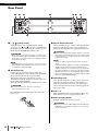
Rear Panel
q [ ]/[ ] (power switch)
Turns the unit’s power (supplied from the AC IN
connector) on [ ]/off [ ]. If power is supplied from
the AC IN connector and this power switch is also on,
the front panel POWER INT indicator is lit.
CAUTION
Even when the power switch is turned off, a small amount of
current is flowing through the unit. When you are not using
the product for a long time, make sure to unplug the power
cord from the AC outlet.
NOTE
Rapidly turning the unit on and off in succession can cause
it to malfunction. After turning the unit off, wait for at least 6
seconds before turning it on again.
w AC IN connector
Connect the supplied AC power cord here. First
connect the AC power cord to the RSio unit, then insert
the power cord plug into an AC power outlet.
The supplied AC power cord features a V-lock
mechanism via a latch, which prevents the power cord
from coming off accidentally.
Insert the cable plug all the way until it locks in securely.
CAUTION
Be sure to turn the power off before connecting or
disconnecting the power cord.
Press the latch button on the plug to disconnect the
power cord.
e EXT DC INPUT connector
This is an XLR-4-32 type connector through which an
external power supply (+24V) can be provided as a
backup for the internal power supply of the RSio64-D.
CAUTION
Before connecting the external power supply, you must turn
off the power of this unit and the power of the external power
supply. Malfunctions or electrical shock may occur if you fail
to observe this caution.
NOTE
• This power supply cannot be turned on/off by the power
switch.
• If an external power supply is connected, the RSio64-D will
operate normally when the internal and external power
supplies are both on, as well as when only one of them is on.
• If both power supplies are on and one of the power supplies
fails during operation, the unit automatically switches to the
other power supply. The state of the power supply is shown
by the front panel POWER indicator.
r Grounding screw
Since the included power cord has a three-conductor
plug, this unit is appropriately grounded if the AC
outlet is grounded. In some cases, you may be able to
reduce hum and interference by connecting ground to
this screw as well.
t SLOT 1–4
Mini-YGDAI I/O cards can be installed in these slots.
Each of the four slots is equipped with an SRC.
y SLOT ACTIVE indicator
Indicates whether the slots are powered.
CAUTION
Do not insert or remove a Mini-YGDAI card if this indicator is
lit. Malfunctions or electrical shock may occur if you fail to
observe this caution.
qe u oyw
ri!0
t

Owner’s Manual
13
Rear Panel
u WORD CLOCK IN connector
This is a BNC connector used to receive word clock
signals. The WORD CLOCK IN connector is internally
terminated with 75Ω.
i Dante [PRIMARY] connector
Dante [SECONDARY] connector
These etherCON (RJ45) connectors allow connection
with Dante devices such as a CL series console using
standard Ethernet cables (CAT5e or better
recommended).
NOTE
• Use STP (Shielded Twisted Pair) cable to prevent
electromagnetic interference. Make sure that the metal
parts of the plugs are electrically connected to the STP
cable shield by conductive tape or comparable means.
• Connect only Dante-compatible devices or Gigabit Ethernet
compatible devices (including compu ters).
•Cables up to 100 meters* long can be used.
*Maximum usable length varies according to the cable
used.
o Dante [PRIMARY LINK/ACT] indicator
Dante [PRIMARY 1G] indicator
Dante [SECONDARY LINK/ACT] indicator
Dante [SECONDARY 1G] indicator
Displays the transmission status with the Dante
network.
!0 Exhaust vent
The RSio64-D is equipped with a cooling fan. Air is
exhausted through this vent, so take care that it is not
blocked by any obstruction.
LINK/ACT
These indicators flash rapidly if the Ethernet
cables are connected properly.
1G
These indicators are lit when the Dante net-
work is functioning as Gigabit Ethernet.
Exhaust vent

14
Owner’s Manual
Connections
Connections
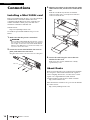
Installing a Mini-YGDAI card
Before you install I/O cards in slots 1–4, you must check the
Yamaha website to determine whether the card is
compatible with the RSio64-D, and to verify the total
number of Yamaha or third-party cards that can be
installed in combination with that card.
Yam a ha website :
http://www.yamahaproaudio.com/
To install an optional mini-YGDAI card, proceed as
follows.
1. Make sure that the power is turned off.
CAUTION
Before installing a Mini-YGDAI I/O card in this unit, you must
turn off the power of this unit and the power of the external
power supply. You must also verify that the SLOT ACTIVE
indicator is unlit. Malfunctions or electrical shock may occur
if you fail to observe this caution.
2. Loosen the screws that hold the slot cover in
place, and remove the slot cover.
Keep the removed slot cover and screws in a safe place.
3. Align the two edges of the card with the guide
rails inside the slot, and insert the card into the
slot.
Push the card all the way into the slot until the
connector of the card is correctly inserted into the
connector inside the slot.
4. Secure the card using the screws that are
attached to the card.
If the card is not secured, malfunction or faulty
operation may occur.
About Dante
Dante is a network audio protocol developed by Audinate.
It is designed to deliver multi-channel audio signals at
various sampling and bit rates, as well as device control
signals over a Gigabit Ethernet (GbE) network.
Visit the Audinate website for more details on Dante:
http://www.audinate.com/
More information on Dante is also posted on the Yamaha
Pro Audio website:
http://www.yamahaproaudio.com/
Slot cover
Card

Owner’s Manual
15
Notes Regarding the Use of Network Switches
Notes Regarding the Use of
Network Switches
We recommend a gigabit-compatible network switch that
provides functions for controlling and monitoring the
network (such as QoS).
Do not use the EEE functionality (*) of network switches
on a Dante network.
Although mutual power consumption settings between
switches that support the EEE functionality are adjusted
automatically, there are some switches for which such
mutual settings are not adjusted correctly.
This may cause EEE to be enabled in Dante networks when
it is not appropriate, resulting in poor synchronization
performance and occasional dropouts.
Therefore we strongly recommend the following.
• If you use managed switches, please disable the EEE
functionality. Do not use switches that prevent EEE
functionality from being disabled.
• When using unmanaged switches, do not use switches
that support EEE functionality. EEE functionality cannot
be disabled for such switches.
* EEE (Energy Efficient Ethernet) is a technology that
reduces switch power consumption during periods of low
network traffic. It is also referred to as Green Ethernet and
IEEE802.3az.
About Dante Controller
Dante Controller is a software application that allows
configuration and audio routing of Dante networks. Use
this application if you plan to connect or set up Dante-
enabled devices that do not feature RSio64-D-native
support. Please download the Dante Controller application
from the website listed below.
Please note that Dante Controller Version 3.2.1 or later
supports RSio64-D.
http://www.yamahaproaudio.com/
To run Dante Controller, a computer must feature a GbE-
compatible Ethernet connector.
Refer to the Dante Controller owner’s manual for details on
Dante Controller.
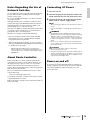
Connecting AC Power
1. Turn the unit off.
2. Connect the plug on the AC power cord to the
AC IN connector on the rear panel of the unit.
3. Connect the other side of the plug on the AC
power cord to a power supply socket.
NOTE
• When removing the AC power cord, perform these steps in
reverse.
• Press the latch button on the plug to disconnect the power
cord.
WARNING
• The RSio64-D has been designed assuming it a proper
ground connection is used. To prevent electrical shock and
damage to devices, use the included AC power cord to
create a secure ground connection. If you do not know how
to make a proper ground connection, contact your Yamaha
dealer.
•Be sure to use only the included power cord with this unit.
Use of a different power cord could result in abnormal heat
and electrical shock.
CAUTION
•Be sure to turn the power off before connecting or
disconnecting the power cord.
•Even when the power switch is turned off, a small amount of
current is flowing through the unit. When you are not using
the product for a long time, make sure to unplug the power
cord from the power supply outlet.
Power on and off
To prevent loud sounds that might harm your hearing or
damage equipment downstream, poweron each unit in the
order of the signal flow. When turning the power off,
reverse this order.

16
Owner’s Manual
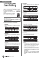
Specifying the audio routing
Specifying the
audio routing
The RSio64-D provides seven preset patterns of audio
routing that connect each slot to the Dante network. There
is also one user pattern (page 17) which the user can edit.
Use the front panel ROUTING
[PATTERN] rotary switch to select the
routing.
Setting the rotary switch to 1–7 selects
preset routing patterns 1–7, and setting
it to 0 selects the user routing pattern.
The preset routing patterns are described below.
PATTERN 1
Dante is connected one-to-one with each slot’s input/
output.
PATTERN 2
The inputs of slot 1 are distributed to the outputs of
slots 2–4.
PATTERN 3
The inputs of slot 1 are distributed to the outputs of slot
2, and the inputs of slot 3 are distributed to the outputs
of slot 4.
PATTERN 4
The inputs and outputs of Slots 1 and 2, and Slots 3 and
4 are interconnected.
PATTERN 5
Dante inputs 1–16* are distributed to the outputs of
each slot.
PATTERN 6
Dante inputs 1–16* are distributed to the outputs of
slots 1 and 2, and Dante inputs 17–32* are distributed
to the outputs of slots 3 and 4.
PATTERN 7
Dante 1–32* and slots 1–2 are connected one-to-one,
and the inputs and outputs of slots 3 and 4 are
connected respectively to each other.
*At 48/44.1 kHz
NOTE
• If the inputs/outputs of an installed Mini-YGDAI card cannot
be assigned in 16-channel units, such as for a 4-channel or
a 8-channel card, audio routing signals from such card are
muted by the slot (e.g., if the Mini-YGDAI card is an 8-
channel card, channels 9–16 are muted).
• For different sampling frequencies, the channels of the
routing pattern are switched automatically, as shown above.
However if SRC is on, the number of the slot’s channels may
change, so there may be cases in which you are unable to
use the above patterns as you would like. In such cases, use
the user pattern.
For example when the sampling frequency is 88.2/96 kHz,
Dante channels 1–8, 9–16, 17–24, and 25-32 are available,
but if SRC is on
for SLOT 1, and the sampling frequency of
that slot is 44.1/48 kHz, then channels 1–16 are available for
SLOT 1.
Making the setting
You can select the routing pattern even when the power
is on. Your selection is applied three seconds after you
switch the routing pattern.
1-16
1-8
48k/44.1k
96k/88.2k 1-8 1-8 1-8
1-16 1-16 1-16
SLOT 1 SLOT 2 SLOT 3 SLOT 4
1-16
1-8
48k/44.1k
96k/88.2k 9-16 17-24 25-32
17-32 33-48 49-64
Dante
1-16
1-8
48k/44.1k
96k/88.2k 1-8 1-8 1-8
1-16 1-16 1-16
SLOT 1 SLOT 2 SLOT 3 SLOT 4
1-16
1-8
48k/44.1k
96k/88.2k 9-16 17-24 25-32
17-32 33-48 49-64
Dante
1-16
1-8
48k/44.1k
96k/88.2k 1-8 1-8 1-8
1-16 1-16 1-16
SLOT 1 SLOT 2 SLOT 3 SLOT 4
1-16
1-8
48k/44.1k
96k/88.2k 9-16 17-24 25-32
17-32 33-48 49-64
Dante
1-16
1-8
48k/44.1k
96k/88.2k 1-8 1-8 1-8
1-16 1-16 1-16
SLOT 1 SLOT 2 SLOT 3 SLOT 4
1-16
1-8
48k/44.1k
96k/88.2k 9-16 17-24 25-32
17-32 33-48 49-64
Dante
1-16
1-8
48k/44.1k
96k/88.2k 1-8 1-8 1-8
1-16 1-16 1-16
SLOT 1 SLOT 2 SLOT 3 SLOT 4
1-16
1-8
48k/44.1k
96k/88.2k 9-16 17-24 25-32
17-32 33-48 49-64
Dante
1-16
1-8
48k/44.1k
96k/88.2k 1-8 1-8 1-8
1-16 1-16 1-16
SLOT 1 SLOT 2 SLOT 3 SLOT 4
1-16
1-8
48k/44.1k
96k/88.2k 9-16 17-24 25-32
17-32 33-48 49-64
Dante
1-16
1-8
48k/44.1k
96k/88.2k 1-8 1-8 1-8
1-16 1-16 1-16
SLOT 1 SLOT 2 SLOT 3 SLOT 4
1-16
1-8
48k/44.1k
96k/88.2k 9-16 17-24 25-32
17-32 33-48 49-64
Dante

Owner’s Manual
17
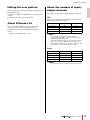
Editing the user pattern
Editing the user pattern
The user pattern lets you freely specify the routing between
Dante and the slots.
To edit the user pattern, use R Remote V4 or a CL/QL series
console.
For details, refer to the respective manuals.
About R Remote V4
This is an application that lets you view and edit the
settings of R series units such as the RSio64-D.
R Remote V4 can be downloaded from the following
website.
http://www.yamahaproaudio.com/
About the number of input/
output channels
The number of audio input/output channels is as follows.
Slots
The slots can provide up to 64 channels (16 channels per
slot) of audio signal input/output.
NOTE
• If an analog Mini-YGDAI card is installed and the
corresponding slot’s SRC is turned on, that slot uses the
RSio64-D’s internal 48 kHz clock.
• If this unit’s sampling frequency is set to 88 kHz or 96 kHz,
and you want to install a Mini-YGDAI card that does not
support 88.2 kHz or 96 kHz, you should turn SRC on for that
slot. If SRC is off, audio signals will not be output.
Dante
NOTE
To change the Dante clock frequency, use Dante Controller.
Frequency Input Output
44.1 kHz 16 ch 16 ch
48 kHz 16 ch 16 ch
88.2 kHz 8 ch 8 ch
96 kHz 8 ch 8 ch
Frequency Input Output
44.1 kHz 64 ch 64 ch
48 kHz 64 ch 64 ch
88.2 kHz 32 ch 32 ch
96 kHz 32 ch 32 ch

18
Owner’s Manual
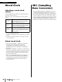
Word Clock
Word Clock
Selecting a word clock
source
Use the WORD CLOCK select key on the front panel to
select the word clock source.
The unit’s clock is synced with the selected word clock
source.
*1 When this is flashing, the unit uses the Dante word clock to
operate and perform input/output.
*2 In order to use MY8-AEB, set AE RSVD switch to the RSVD
position.
*3 If you want to change the frequency of the Dante word clock,
use Dante Controller.
About word clock
• If you select “WCLK IN” or “SLOT1 1/2,” the unit is
automatically set to Enable Sync To External
(synchronize to an external clock). If you select
“DANTE,” Enable Sync To External is automatically
turned off.
If you select “WCLK IN” or “SLOT1 1/2,” and this unit is
a clock slave of the Dante network, the same clock should
be input to the clock master device and to this device.
You can use Dante Controller to check which device is
the current clock master.
• If the word clock signal from the selected word clock
source is cut off, the unit switches to the “DANTE”
setting (Enable Sync To External automatically turns
off), and operates with the clock frequency that is
specified by Dante.
SRC (Sampling
Rate Converter)
• Even if the Mini-YGDAI card installed in a slot is not
synchronized with the Dante network, connection is
possible without having to change the respective clocks.
• The output signal from the slot synchronizes with the
clock from the slot’s input signal or with the clock that is
input via WORD CLOCK IN. However, if the card’s SRC
is enabled, the main unit’s SRC will be disabled, and
signals in sync with the main unit’s clock will be output.
WCLK IN
This is lit if the RSio64-D is using the word
clock that is being input from the rear panel
[WORD CLOCK IN] connector. This flashes if
there is no valid word clock input
*1
.
SLOT1 1/2
This is lit if the channel 1/2 word clock of slot 1
is being used. This flashes if there is no valid
word clock input
*1
. The channel 7/8 word clock
is used when using the MY8-AEB
*2
.
DANTE
This is lit if the Dante network’s word clock
*3
is
being used. (If no valid Dante signal is being
input, the clock generated by the internal Dante
module is used.)

Owner’s Manual
19
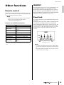
Other functions
Other functions
Remote control
The same operations performed from the RSio64-D’s front
panel, such as turning SRC on/off, can be performed from
a device that supports remote control.
NOTE
For the latest information about remote control compatible
devices, refer to the Yamaha Pro Audio website:
http://www.yamahaproaudio.com/
Remote controllable parameters
* DANTE PATCH: Specifies which channels of the CL/QL series
console are input to which of the RSio64-D’s Dante 1–64 chan-
nels.
IDENTIFY
From a Yamaha CL/QL series console, from R Remote V4,
or from Dante Controller, you can identify a specific
RSio64-D unit from among multiple network-connected
devices. When you specify the IDENTIFY operation, all
front panel indicators on that unit except for the POWER
(INT/EXT) indicator will flash for ten seconds.
Panel lock
You can lock the panel to prevent unintended changes and
operations.
While the lock is engaged, all controllers on the front panel
are inoperable. To engage the lock, press and hold the
SLOT 1 and SLOT 4 [SRC] keys for at least 3 seconds. All
front panel indicators (except the power indicator) flash,
and operation is locked. To disengage the lock, press and
hold the SLOT 1 and SLOT 4 [SRC] keys for at least 3
seconds.
NOTE
• If you turn off the power while panel lock is engaged, panel
lock will still be engaged the next time the power is turned
on.
•Even if the front panel is locked, you can use remote control
to make changes to the settings.
Parameter Description
SRC ON/OFF Turns SRC on or off.
WORD CLOCK
Selects the source used as the mas-
ter clock.
USER PATTERN
Lets you specify the user routing pat-
tern.
DANTE PATCH* Lets you change the Dante patch.
ROUTING PATTERN Displays the pattern number.
SRC SOURCE CLOCK Shows the source used by the SRC.
POWER INT/EXT Shows the power supply status.
SYSTEM/SYNC STATUS Shows the system sync status.
DEVICE LABEL
Shows the UNIT ID/device name
(label).
Press simultaneously for
at least three seconds

20
Owner’s Manual
Other functions
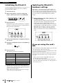
Initializing the RSio64-D
To return (initialize) the internal memory to its factory-set
state, for example if you move the unit to a different
location, proceed as follows.
1. Turn the unit off.
2. On the front panel, set device setting DIP
switch 7 down and switch 8 up (INITIALIZE).
3. Turn the unit on.
Initialization begins. When initialization is completed,
the SLOT 1–4 [LOCK] and SLOT 1–4 [SRC] indicators
flash green and red alternately.
4. Verify that initialization is completed, and turn
the unit off.
5. Set device setting DIP switches 7 and 8 both up
(NORMAL).
6. Turn the unit on.
The following parameters are initialized.
(*1) The third and fourth characters of the Dante device label
depend on device setting DIP switch 1 and the SETUP [UNIT
ID] rotary switch. The lower six digits depend on the lower six
digits of the unit’s MAC address.
* When shipped from the factory, all of the device setting DIP
switches are set to the upward position.
Updating the RSio64-D’s
hardware settings
If the SLOT 1–4 [LOCK] indicators and the SLOT 1–4
[SRC] indicators are alternately flashing red and the unit
does not start up, it may be that the unit’s hardware settings
were not updated when updating the firmware. In this case,
proceed as follows to update the RSio64-D’s hardware
settings.
1. While holding down the SLOT 3 [SRC] key, turn
the power on again.
Updating of the unit’s hardware settings begins. During
the update, the SLOT 1 [LOCK] indicator and the
SLOT 1 [SRC] indicator light simultaneously. To
indicate the status during the update process, both the
[LOCK] indicator and the [SRC] indicator successively
light in the order of SLOT 2 SLOT 3 SLOT 4.
When the update is completed, the eight indicators
flash once and then return to the normal illumination
status.
If you are using the card’s
SRC
If your card features an SRC (MY8-AE96S), you can use the
card’s SRC instead of the main unit’s SRC.
To use the card’s SRC, set device setting DIP switch 6 on the
front panel to the down position.
When this function is enabled, the [SRC] key on the front
panel of the main unit will be used to turn the card’s SRC
on or off.
• Changes made to device setting DIP switch 6 will
become effective in three seconds.
• For a slot that has a card without an SRC inserted, the
[SRC] key will turn the unit’s SRC on or off regardless of
the switch position.
Parameter Initialized setting
SLOT 1–4 SRC OFF
WORD CLOCK SELECT DANTE/48 kHz
USER PATTERN
Same routing settings as preset pat-
tern 1
STATIC IP (Manual) 0.0.0.0
Panel Lock Lock defeated
Dante patches All off
Dante device label Y001-Yamaha-RSio64-D-123456
(*1)
7 8
ON
12345678
7 8
Seite laden ...
Seite laden ...
Seite laden ...
Seite laden ...
Seite laden ...
Seite laden ...
Seite laden ...
Seite laden ...
Seite laden ...
Seite laden ...
-
 1
1
-
 2
2
-
 3
3
-
 4
4
-
 5
5
-
 6
6
-
 7
7
-
 8
8
-
 9
9
-
 10
10
-
 11
11
-
 12
12
-
 13
13
-
 14
14
-
 15
15
-
 16
16
-
 17
17
-
 18
18
-
 19
19
-
 20
20
-
 21
21
-
 22
22
-
 23
23
-
 24
24
-
 25
25
-
 26
26
-
 27
27
-
 28
28
-
 29
29
-
 30
30


Yamaha RSio64 Bedienungsanleitung
- Kategorie
- Zusätzliche Musikausrüstung
- Typ
- Bedienungsanleitung
in anderen Sprachen
- English: Yamaha RSio64 Owner's manual
- français: Yamaha RSio64 Le manuel du propriétaire
- español: Yamaha RSio64 El manual del propietario
- italiano: Yamaha RSio64 Manuale del proprietario
- русский: Yamaha RSio64 Инструкция по применению
- Nederlands: Yamaha RSio64 de handleiding
- português: Yamaha RSio64 Manual do proprietário
- dansk: Yamaha RSio64 Brugervejledning
- polski: Yamaha RSio64 Instrukcja obsługi
- čeština: Yamaha RSio64 Návod k obsluze
- svenska: Yamaha RSio64 Bruksanvisning
- Türkçe: Yamaha RSio64 El kitabı
- suomi: Yamaha RSio64 Omistajan opas
- română: Yamaha RSio64 Manualul proprietarului