
DEUTSCH
Ultraschallsensor
Betriebsanleitung
Sicherheitshinweise
‡ Vor der Inbetriebnahme die Betriebsanleitung lesen.
‡ Anschluss, Montage und Einstellung nur durch Fachpersonal.
‡ Gerät bei Inbetriebnahme vor Feuchte und Verunreinigung
schützen.
‡ Kein Sicherheitsbauteil gemäß EU-Maschinenrichtlinie.
Bestimmungsgemäße Verwendung
Der UC 12 ist ein Ultraschallsensor und wird zum berührungs-
losen Erfassen von Sachen, Tieren und Personen eingesetzt.
Inbetriebnahme
!a
Modus 1: Sensor auf Objekt einstellen
1.1 Objekt im gewünschten Schaltabstand vor den Sensor
bringen
– LED leuchtet gelb oder grün (je nach Zustand des
Schaltausganges).
1.2 Taste solange drücken
– LED geht kurzzeitig aus (als Feedback)
1.3 bis LED gelb blinkt (nach ca. 2 s).
1.4 Taste loslassen
– LED leuchtet gelb.
Der Schaltpunkt ist dauerhaft gespeichert, der Sensor ist
betriebsbereit.
Wird unter Punkt 1.2 kein Objekt gesehen, bzw. ist das
Objekt außerhalb des Erfassungsbereichs, so blinkt die LED
für 3 Sekunden schnell rot (Fehleranzeige). Die alten
Schaltpunkte werden beibehalten.
Weitere Funktionen
!b
Modus 2: Sensor auf Fensterbereich einstellen
2.1 Objekt in sensornahen Schaltabstand vor den Sensor
bringen
– LED leuchtet gelb oder grün (je nach Zustand des
Schaltausganges).
2.2 Taste solange drücken
– LED geht kurzzeitig aus (als Feedback)
– LED blinkt gelb (nach ca. 2 s)
2.3 bis LED grün blinkt (nach ca. 5 s).
2.4 Taste loslassen
– LED blinkt abwechselnd grün-gelb.
2.5 Objekt in sensorfernen Schaltabstand vor den Sensor
bringen.
2.6 Taste erneut drücken
– LED blinkt grün.
2.7 Nach ca. 1 s Taste loslassen
– LED leuchtet grün.
Das Fenster mit sensornahem und sensorfernem Schalt-
punkt ist dauerhaft gespeichert, der Sensor ist betriebsbereit.
Versucht der Anwender, die Fensterbreite < 5 mm
einzustellen, wird 1 (Schaltpunkt mit einem Objekt)
eingestellt.
Wird unter Punkt 2.2 kein Objekt gesehen, bzw. ist das
Objekt außerhalb des Erfassungsbereichs, so blinkt die LED
für 3 Sekunden schnell rot (Fehleranzeige). Die alten
Schaltpunkte werden beibehalten.
Wird ein Abstand im Erfassungsbereich des Sensors gelernt
und der zweite außerhalb des Erfassungsbereiches, blinkt
LED für 3 Sekunden schnell rot (Fehleranzeige). Die alten
Schaltpunkte werden beibehalten.
!c
Modus 3: Sensor auf Hintergrund einstellen
3.1 Zwangsreflektor (= definierter Hintergrund) vor den
Sensor bringen
– LED leuchtet gelb oder grün (je nach Zustand des
Schaltausganges).
3.2 Taste solange drücken
– LED geht kurzzeitig aus (als Feedback)
– LED blinkt gelb (nach ca. 2 s)
3.3 bis LED grün blinkt (nach ca. 5 s).
3.4 Taste loslassen
– LED blinkt abwechselnd grün-gelb.
3.5 Taste erneut drücken
– LED blinkt grün
3.6 bis grüne LED leuchtet (ca. 10 s).
3.7 Taste loslassen
– LED leuchtet gelb.
Das Fenster wird symmetrisch mit ≥ 10 mm um den
Zwangsreflektor gelegt.
Wird unter Punkt 3.2 kein Objekt gesehen, bzw. ist das
Objekt außerhalb des Erfassungsbereichs, so blinkt LED für
3 Sekunden schnell rot (Fehleranzeige). Die alten
Schaltpunkte werden beibehalten.
Wird ein Abstand im Erfassungsbereich des Sensors gelernt
und der zweite außerhalb des Erfassungsbereiches, blinkt
LED für 3 Sekunden schnell rot (Fehleranzeige). Die alten
Schaltpunkte werden beibehalten.
2
Taste deaktivieren/aktivieren
4.1 Sensor spannungslos schalten (Betriebsspannung
abschalten).
4.2 Taste drücken, Betriebsspannung zuschalten, Taste
weiterhin gedrückt halten
– LED blinkt schnell grün
4.3 bis LED gelb blinkt (nach ca. 5 s).
4.4 Taste loslassen
– LED zeigt Taste aktiv/inaktiv.
LED blinkt schnell gelb = Taste aktiv.
LED blinkt schnell grün = Taste inaktiv.
4.5 Während die grüne LED blinkt, wird bei jedem
Tastendruck die Tasterfunktion invertiert.
LED blinkt schnell gelb = Taste aktiv.
LED blinkt schnell grün = Taste inaktiv.
Wird die Taste für 10 s nicht betätigt, ist die eingestellte
Funktion übernommen, der Sensor ist betriebsbereit.
3
Werkseinstellung
5.1 Sensor spannungslos schalten (Betriebsspannung
abschalten).
5.2 Taste drücken, Betriebsspannung zuschalten, Taste
weiterhin gedrückt halten
– LED blinkt schnell grün, nach 5 s blinkt LED gelb
5.3 bis LED gelb oder grün (je nach Zustand des
Schaltausganges) leuchtet (nach ca. 13 s).
5.4 Taste loslassen.
Wartung
SICK-Sensoren sind wartungsfrei. Wir empfehlen, in regelmäßi-
gen Abständen
- die Grenzflächen zu reinigen,
- Verschraubungen und Steckverbindungen zu überprüfen.
B
A
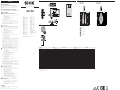
UC12- 11231 11235 12231 12235
Blindzone 20 mm 55 mm
Betriebstastweite (Grenztastweite) 20 ... 150 mm (250 mm) 55 ... 250 mm (350 mm)
Öffnungswinkel der Schallkeule siehe
1
Ultraschallfrequenz ca. 380 kHz ca. 500 kHz
Auflösung 0,18 mm
Reproduzierbarkeit ±0,15 %
Genauigkeit ≤ 2 %
1)
Versorgungsspannung U
V
2)
DC 10 ... 30 V
Restwelligkeit 10 %
Stromaufnahme ≤ 40 mA
Schaltausgang
3)
PNP, U
V
– 2 V, I
max
= 500 mA NPN, –U
V
+ 2 V, I
max
= 500 mA PNP, U
V
– 2 V, I
max
= 500 mA NPN, –U
V
+ 2 V, I
max
= 500 mA
Ansprechzeit 27 ms 27 ms
Schaltfolge < 25/s < 25/s
Schalthysterese 2,0 mm
Bereitschaftsverzug < 300 ms
Anzeigeelemente Duo-LED grün/gelb
Bedienelement(e) Teach-in-Knopf
Anschlussart Steckverbinder M12, 4-polig
Schutzart nach EN 60529 IP 67
Betriebsumgebungstemperatur –20 °C ... + 70 °C
Gewicht ca. 75 g
Gehäusematerial
4)
Zink-Druckguss
1
1)
Bezug: Grenztastweite
2)
Grenzwerte, verpolsicher
Betrieb im kurzschlussgeschützten Netz max. 8 A
3)
Ausgänge kurzschlussgeschützt
4)
Ultraschallwandler: Polyurethanschaum,
Epoxidharz mit Glasanteilen
9,24
1024
7, 5
22,5
5,5
15
50,5
5
2
43,5
21,4
1
L+
Q
M
4
3
2
Q
brn
blk
blu
wht
50 25 0 25 50
[mm]
50
100
200
150
250
300
350
UC12-1123_
150 mm
1
2
3
4
100 50 0 50 100
[mm]
50
100
200
150
250
300
350
400
450
UC12-1223_
250 mm
4
1
2
3
2
Betriebstastweite
Grenztastweite
3
1
4
Ausgerichtete Platte
500 x 500 mm
2
Rohr-Durchmesser
10 mm
UC12-11231
UC12-11235
UC12-12231
UC12-12235
5
5
Empfangsanzeige
8010984/10MA/2018-11/8M_PK
UC 12
BZ int48
Phone +31 (0) 30 229 25 44
Please find detailed addresses and further locations in all major industrial
nations at www.sick.com
Australia
Phone +61 (3) 9457 0600
Austria
Phone +43 (0) 2236 62288-0
Belgium/Luxembourg
Phone +32 (0) 2 466 55 66
Brazil
Phone +55 11 3215-4900
Canada
Phone +1 905.771.1444
Czech Republic
Phone +420 2 57 91 18 50
Chile
Phone +56 (2) 2274 7430
China
Phone +86 20 2882 3600
Denmark
Phone +45 45 82 64 00
Finland
Phone +358-9-25 15 800
France
Phone +33 1 64 62 35 00
Germany
Phone +49 (0) 2 11 53 01
Hong Kong
Phone +852 2153 6300
Hungary
Phone +36 1 371 2680
India
Phone +91-22-6119 8900
Israel
Phone +972-4-6881000
Italy
Phone +39 02 27 43 41
Japan
Phone +81 3 5309 2112
Malaysia
Phone +603-8080 7425
Mexico
Phone +52 (472) 748 9451
Netherlands
New Zealand
Phone +64 9 415 0459
Norway
Phone +47 67 81 50 00
Poland
Phone +48 22 539 41 00
Romania
Phone +40 356-17 11 20
Russia
Phone +7 495 283 09 90
Singapore
Phone +65 6744 3732
Slovakia
Phone +421 482 901 201
Slovenia
Phone +386 591 78849
South Africa
Phone +27 (0)11 472 3733
South Korea
Phone +82 2 786 6321
Spain
Phone +34 93 480 31 00
Sweden
Phone +46 10 110 10 00
Switzerland
Phone +41 41 619 29 39
Taiwan
Phone +886-2-2375-6288
Thailand
Phone +66 2 645 0009
Turkey
Phone +90 (216) 528 50 00
United Arab Emirates
Phone +971 (0) 4 88 65 878
United Kingdom
Phone +44 (0)17278 31121
USA
Phone +1 800.325.7425
Vietnam
Phone +65 6744 3732

9.24
1024
7. 5
22.5
5.5
15
50.5
5
2
43.5
21.4
B
A
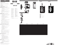
UC12- 11231 11235 12231 12235
Blind zone 20 mm 55 mm
Operating scanning distance
(limiting scanning distance) 20 ... 150 mm (250 mm) 55 ... 250 mm (350 mm)
Angle of sound-beam see
1
Ultrasonic frequency Approx. 380 kHz Approx. 500 kHz
Resolution 0.18 mm
Reproducibility ±0.15 %
Accuracy ≤ 2 %
1)
Supply voltage V
S
2)
10 ... 30 V DC
Residual ripple 10 %
Current consumption ≤ 40 mA
Switching output
3)
PNP, V
S
– 2 V, I
max
= 500 mA NPN, –V
S
+ 2 V, I
max
= 500 mA PNP, V
S
– 2 V, I
max
= 500 mA NPN, –V
S
+ 2 V, I
max
= 500 mA
Response time 27 ms 27 ms
Switching frequency < 25/s < 25/s
Switching hysteresis 2.0 mm
Standby delay < 300 ms
Indicator Double-LED green/yellow
Control element(s) Teach-in button
Connection type Plug M12, 4-pin
Enclosure rating according to EN 60529 IP 67
Ambient operating temperature –20 °C ... + 70 °C
Weight Approx. 75 g
Housing material
4)
Zinc-die cast
1
1)
Reference: limiting scanning distance
2)
Limit values, reverse polarity protected
Operation in short-circuit protected network max. 8 A
3)
Output short-circuit protected
4)
Ultrasonic transducer: Polyurethane-foam, glass epoxy resin
1
L+
Q
M
4
3
2
Q
brn
blk
blu
wht
50 25 0 25 50
[mm]
50
100
200
150
250
300
350
UC12-1123_
150 mm
1
2
3
4
100 50 0 50 100
[mm]
50
100
200
150
250
300
350
400
450
UC12-1223_
250 mm
4
1
2
3
2
Operating scanning distance
Limiting scanning distance
3
1
4
Aligned plate
500 x 500 mm
2
Pipe diameter
10 mm
UC12-11231
UC12-11235
UC12-12231
UC12-12235
5
5
Signal strength indicator
ENGLISH
Ultrasonic sensor
Operating Instructions
Safety Specifications
‡ Read the operating instructions before starting operation.
‡ Connection, assembly, and settings only by competent
technicians.
‡ Protect the device against moisture and soiling when
operating.
‡ No safety component in accordance with EU machine
guidelines.
Proper Use
The UC 12 is an ultrasonic sensor and is used for
non-contact detection of objects, animals, and people.
Starting Operation
!a
Mode 1: Set the sensor to the object.
1.1 Place the object at the desired switching distance from
the sensor.
– LED light yellow or green (depending on the state of
the switching output).
1.2 Press the button
– LED switches off for a short time (as feedback)
1.3 until LED yellow blinks (after approx. 2 s).
1.4 Release button
– LED lights yellow.
The switching point is stored permanently, and the sensor
is ready to operate.
If no object is seen under item 1.2 or the object is outside
of the detection range, the LED blinks quickly for 3
seconds red (error display). The old switching points are
maintained.
Additional Functions:
!b
Mode 2: Set the sensor to the window area
2.1 Place the object at switching distance near the sensor
in front of the sensor.
– LED light yellow or green (depending on the state of
the switching output).
2.2 Press the button
– LED switches off for a short time (as feedback)
– LED blinks yellow (after approx. 2 s)
2.3 until LED green blinks (after approx. 5 s).
2.4 Release button
– LED blinks green and yellow alternately.
2.5 Place the object at switching distance far from the
sensor in front of the sensor.
2.6 Press the button again
– LED blinks green.
2.7 Release the button after approx. 1 s
– LED lights green.
The window with the switching point near the sensor and
far from it is stored permanently, and the sensor is ready to
operate.
If the user tries to set the window width < 5 mm, 1
(switching point with an object) is set.
If no object is seen under item 2.2 or the object is outside
of the detection range, the LED blinks quickly for 3
seconds red (error display). The old switching points are
maintained.
If a distance is taught in the detection range of the sensor
and a second one is outside of the detection range, the
LED blinks quickly for 3 seconds red (error display). The
old switching points are maintained.
!c
Mode 3: Set the sensor to the background.
3.1 Place reflector (= defined background) in front of the
sensor:
– LED light yellow or green (depending on the state of
the switching output).
3.2 Press the button
– LED switches off for a short time (as feedback)
– LED blinks yellow (after approx. 2 s)
3.3 until LED green blinks (after approx. 5 s).
3.4 Release button
– LED blinks green and yellow alternately.
3.5 Press the button again
– LED blinks green
3.6 until green LED lights (approx. 10 s).
3.7 Release button
– LED lights yellow.
The window is set symmetrically around the reflector with
≥ 10 mm.
If no object is seen under item 3.2 or the object is outside
of the detection range, the LED blinks quickly for 3
seconds red (error display). The old switching points are
maintained.
If a distance is taught in the detection range of the sensor
and a second one is outside of the detection range, the
LED blinks quickly for 3 seconds red (error display). The
old switching points are maintained.
2
Deactivate/activate button
4.1 Switch off the power to the sensor (switch off the
supply voltage).
4.2 Press the button, switch on the supply voltage, keep
the button pressed down,
– LED blinks green
4.3 until LED yellow blinks (after approx. 5 s).
4.4 Release button
– LED indicates button is active/inactive.
LED blinks quickly yellow = button is active.
LED blinks green quickly = button is inactive.
4.5 While the green LED blinks, the scanner function is
inverted each time you press the button.
LED blinks quickly yellow = button is active.
LED blinks green quickly = button is inactive.
If the button is not pressed for 10 s, the set function is
adopted; the sensor is ready to operate.
3
Ex-works setting
5.1 Switch off the power to the sensor (switch off the
operating voltage).
5.2 Press the button, switch on the operating voltage, keep
the button pressed down,
– LED blinks quickly green, LED blinks yellow after 5 s
5.3 until LED yellow or green lights (after approx. 13 s
depending on the state of the switching output).
5.4 Release button.
Maintenance
SICK sensors do not require any maintenance. We recommend
that you clean the external lens surfaces and check the screw
connections and plug-in connections at regular intervals.
8010984/10MA/2018-11/8M_PK
UC 12
BZ int48
Phone +31 (0) 30 229 25 44
Please find detailed addresses and further locations in all major industrial
nations at www.sick.com
Australia
Phone +61 (3) 9457 0600
Austria
Phone +43 (0) 2236 62288-0
Belgium/Luxembourg
Phone +32 (0) 2 466 55 66
Brazil
Phone +55 11 3215-4900
Canada
Phone +1 905.771.1444
Czech Republic
Phone +420 2 57 91 18 50
Chile
Phone +56 (2) 2274 7430
China
Phone +86 20 2882 3600
Denmark
Phone +45 45 82 64 00
Finland
Phone +358-9-25 15 800
France
Phone +33 1 64 62 35 00
Germany
Phone +49 (0) 2 11 53 01
Hong Kong
Phone +852 2153 6300
Hungary
Phone +36 1 371 2680
India
Phone +91-22-6119 8900
Israel
Phone +972-4-6881000
Italy
Phone +39 02 27 43 41
Japan
Phone +81 3 5309 2112
Malaysia
Phone +603-8080 7425
Mexico
Phone +52 (472) 748 9451
Netherlands
New Zealand
Phone +64 9 415 0459
Norway
Phone +47 67 81 50 00
Poland
Phone +48 22 539 41 00
Romania
Phone +40 356-17 11 20
Russia
Phone +7 495 283 09 90
Singapore
Phone +65 6744 3732
Slovakia
Phone +421 482 901 201
Slovenia
Phone +386 591 78849
South Africa
Phone +27 (0)11 472 3733
South Korea
Phone +82 2 786 6321
Spain
Phone +34 93 480 31 00
Sweden
Phone +46 10 110 10 00
Switzerland
Phone +41 41 619 29 39
Taiwan
Phone +886-2-2375-6288
Thailand
Phone +66 2 645 0009
Turkey
Phone +90 (216) 528 50 00
United Arab Emirates
Phone +971 (0) 4 88 65 878
United Kingdom
Phone +44 (0)17278 31121
USA
Phone +1 800.325.7425
Vietnam
Phone +65 6744 3732
-
 1
1
-
 2
2


in anderen Sprachen
- English: SICK UC 12 Operating instructions
Verwandte Artikel
-
SICK UM18-5111 Bedienungsanleitung
-
-
-
-
-
-
-
-
-