Benning PV 2 Bedienungsanleitung
- Kategorie
- Messung
- Typ
- Bedienungsanleitung

Kurzanleitung
BENNING PV 2
1. Wichtige Informationen
m
Lesen Sie bitte die ausführliche Bedienungsanleitung (http://tms.
benning.de/pv2) bevor Sie das BENNING PV 2 verwenden.
Das BENNING PV 2 darf ausschließlich durch ausgebildetes Fach-
personal bedient werden.
c
Der Anschluss an den PV-Generator ist ausschließlich gemäß den
Anschlussbildern der Bedienungsanleitung vorzunehmen.
Nicht benötigte Messleitungen sind von dem BENNING PV 2 zu
trennen.
c
Vor der Messung ist der PV-Generator allpolig vom PV-Wechselrich-
ter zu trennen!
Der PV-Generator darf die maximale Leerlaufspannung von 1000 V,
den maximalen Kurzschlussstrom von 15 A und die maximale DC-
Leistung (P = Uoc x Isc) von 10 kW nicht überschreiten.
Die Messungen sind am einzelnen PV-Strang durchzuführen!
Es ist sicherzustellen, dass alle Schaltgeräte und Trennvorrichtun-
gen offen sind und alle PV-Stränge gegeneinander isoliert sind.
Beachten Sie, dass sich die Kurzschlussströme (Isc) von parallel
geschalteten PV-Strängen addieren und sich zusätzlich durch vor-
handene Kapazitäten des PV-Generators erhöhen können.
Nichtbeachtung kann zur Beschädigung des BENNING PV 2 führen!
cDas Prüfgerät BENNING PV 2 direkt nach beendeter Prüfung vom
PV-Generator trennen.
c
Messspitzen nicht berühren! Bei Isolationswiderstandsmessungen
können hohe elektrische Spannungen an den Messspitzen anliegen.
cWährend der Messung keine Metallteile des Prüfobjektes berühren.
cDer PV-Generator muss von der elektrischen Hauptversorgung iso-
liert sein!
Weder Plus- noch Minuspol des PV-Generators darf geerdet sein!
c
Über die 4 mm Messleitungen sind Spannungsmessungen an
Steckdosenstromkreise möglich. Das BENNING PV 2 darf über die
4 mm Prüfbuchsen nur in Strom kreisen der Überspannungskate-
gorie III mit max. 300 V AC/DC Leiter gegen Erde benutzt werden.
Hierzu sind vorher die PV-Messleitungen von den PV-Prüfbuch sen
zu trennen.
cVor jeder Inbetriebnahme überprüfen Sie das Gerät und die Leitun-
gen auf Be schädigungen. Ein beschädigtes Gerät nicht verwenden!
mVerwenden Sie ausschließlich die im Lieferumfang des
BENNING PV 2 enthaltenen Messleitungen.
cDas BENNING PV 2 ist ausschließlich zur Messung in trockener
Umgebung vorgesehen.
16. Fehlercodes
Fehlercode Abhilfe
Interne Sicherung defekt,
vgl. Kapitel 9.5, „Sicherungswechsel“
Die Elektronik des BENNING PV 2 hat die max. zu-
lässige Temperatur erreicht. Das BENNING PV 2
vom Messobjekt trennen und abkühlen lassen.
Der DC-Kurzschlussstrom hat den Maximalwert
von 15 A überschritten. Die Messung wurde ab-
gebrochen.
Die DC-Leerlaufspannung hat den Maximalwert
von 1000 V überschritten. Die Messung wurde
abgebrochen.
Die DC-Leistung hat den Maximalwert von 10 kW
überschritten. Die Messung wurde abgebrochen.
Trennen Sie das BENNING PV 2 umgehend von
dem PV-Generator
Das BENNING PV 2 bitte an einen autorisierten
Service-Händler zurücksenden, vgl. Adresse aus
Kapitel 9.6 „Kalibrierung“
Das BENNING PV 2 bitte an einen autorisierten
Service-Händler zurücksenden, vgl. Adresse aus
Kapitel 9.6 „Kalibrierung“.
Das BENNING PV 2 bitte an einen autorisierten
Service-Händler zurücksenden, vgl. Adresse aus
Kapitel 9.6 „Kalibrierung“.
oder
Das BENNING PV 2 bitte an einen autorisierten
Service-Händler zurücksenden, vgl. Adresse aus
Kapitel 9.6 „Kalibrierung“.
etc.
Das BENNING PV 2 bitte an einen autorisierten
Service-Händler zurücksenden, vgl. Adresse aus
Kapitel 9.6 „Kalibrierung“.
Das BENNING PV 2 ist nicht korrekt kalibriert, vgl.
Kapitel 9.6 „Kalibrierung“.
Die Speicherung ist fehlgeschlagen. Bitte spei-
chern Sie die Messwerte erneut auf den nächst
freien Speicherplatz.
Die Speicherung im NFC-Chip ist fehlgeschlagen.
Bitte entfernen Sie das NFC-fähige Gerät von
dem BENNING PV 2.
Weitere Fehlercodes siehe ausführliche Bedienungsanleitung (http://tms.benning.de/pv2).
17. Optionales Zubehör
PC-Software BENNING SOLAR Manager (TN 050423)
Saugnapf-Temperaturfühler für BENNING SUN 2 (TN 050424)
PV-Modulhalterung für BENNING SUN 2 (TN 050425)
Stromzangenadapter BENNING CC 3 (TN 044038)
Messleitung BENNING TA 5, Länge: 40 m (TN 044039)
500V
250V 1000V
PV 2
DIN EN 62446 (VDE 0126-23), DIN EN 61829 (VDE 0126-24)
Auto Mode
a Vo/c, Is/c, MΩ
b Vmpp, Impp, FF
c a + b
d
Auto
Ω
NULL
RPE
Mode
RISO
VISO
14. Messbereiche und Grenzwerte
Funktion Bereich
RPE/V ȍȍ99$&'&
RISO (2-polig) 0ȍ0ȍ
Vo/c 5 V - 1000 V DC
Is/c 0,5 A - 20 A DC
RISO (AUTO-Messung) 0ȍ0ȍ
I 0,1 A - 40 A AC/DC
ISO-Prüfspannung Grenzwert Isolationswiderstand
250 V 0ȍ
500 V/ 1000 V 0ȍ
15. Einstellen von Datum und Uhrzeit
1. Schalten Sie das BENNING PV 2 aus.
2. Drücken und halten Sie die
-
Taste
8 und betätigen Sie gleichzeitig die
RISO -Taste 4 und die Mode -Taste 5 am BENNING PV 2.
3. Das Datum-/Uhrzeitformat wird wie folgt angezeigt:
MM.DD = Monat (1-12).Tag (1-31)
YYYY = Jahr
HH.mm = Stunden (0-23).Minuten (0-59)
SS = Sekunden (0-59)
4. Drücken Sie die RPE -Taste 2, um ein Datum-/Uhrzeitfeld anzuwählen.
5. Ein blinkendes Feld verdeutlicht, dass dieses Feld eingestellt werden kann.
6. Über die -Taste J und die
-
Taste
8 wird der Wert erhöht bzw. verringert.
Mit jeder Änderung wird das Sekundenfeld auf Null gesetzt.
7. Schalten Sie das Gerät aus, um die Einstellung zu speichern.
Hinweis:
Befindet sich das BENNING PV 2 in Funkverbindung mit dem BENNING SUN 2,
synchronisiert sich das Datum/ die Uhrzeit des BENNING PV 2 automatisch nach
ca. 10 s auf das Datum/ die Uhrzeit des BENNING SUN 2, wenn eine Abweichung
!0LQIHVWJHVWHOOWZLUG%(11,1*6810DVWHUĺ%(11,1*396ODYH
12. Funkverbindung zum BENNING SUN 2
Das BENNING PV 2 kann die Messwerte (Solare Einstrahlung, PV-Modul-/ Umge-
bungstemperatur und Datum-/Zeitstempel) des optionalen BENNING SUN 2 (TN
050420) per Funk empfangen.
Typische Funkreichweite im Freigelände: ca. 30 m
Koppeln mit BENNING SUN 2
1. Entfernen Sie alle elektronischen Geräte in unmittelbarer Umgebung.
2. Schalten Sie das BENNING PV 2 und das BENNING SUN 2 aus.
3. Drücken und halten Sie die beiden Tasten-ON/OFF am BENNING SUN 2.
4. Drücken und halten Sie gleichzeitig die RISO -Taste 4 und die Mode -Taste 5 am
BENNING PV 2.
5. Das BENNING PV 2 signalisiert die erfolgreiche Kopplung über einen Signalton
und der Einblendung der Serien-Nr. des BENNING SUN 2.
6. Im LCD-Display 1 des BENNING PV 2 wird das Symbol „W/m2“ eingeblendet.
Entkoppeln vom BENNING SUN 2
1. Entfernen Sie alle elektronischen Geräte in unmittelbarer Umgebung.
2. Schalten Sie das BENNING PV 2 aus.
3. Drücken und halten Sie die RISO -Taste 4 und die Mode -Taste 5 am BENNING PV 2
für ca. 10 Sekunden gedrückt.
4. Das BENNING PV 2 signalisiert die Entkopplung vom BENNING SUN 2 über
ein Signalton und der Löschung des LCD-Display.
5. Im LCD-Display 1 des BENNING PV 2 wird das Symbol „RPEȍ³HLQJHEOHQGHW
Aktivieren/Deaktivieren der Funkübertragung des BENNING SUN 2
1. Koppeln Sie das BENNING PV 2 mit dem BENNING SUN 2.
2. Zum Aktivieren/Deaktivieren der Funkübertragung drücken und halten Sie am
BENNING SUN 2 die -Taste und drücken Sie gleichzeitig die -Taste. Im
LCD-Display wird ein blinkendes Dreieck angezeigt.
3. Das BENNING PV 2 empfängt die Messwerte, sobald die solare Einstrahlung
(W/m²) im LCD-Display 1 angezeigt wird.
4. Eine AUTO-Messung (Mode a - c) speichert zusätzlich die Temperaturwerte
und den Datum-/Zeitstempel des BENNING SUN 2.
5. Sollte sich das BENNING PV 2 außerhalb der Funkreichweite des
BENNING SUN 2 befinden, blinkt das Symbol „W/m²“ auf dem LCD-Display
1. Ebenso erscheint „_ _ _ _“ auf dem LCD-Display, wenn der Messwert der
solaren Einstrahlung außerhalb des Messbereiches liegt.
Hinweis:
Sollte das BENNING PV 2 kein Funksignal vom BENNING SUN 2 empfangen, werden
die Displayanzeigen mit dem Datum-/Zeitstempel des BENNING PV 2 gespeichert.
13. Darstellung der I-U Kennlinie über APP „BENNING PV Link“
Voraussetzung: NFC-fähiges Android-Gerät
Die APP ermöglicht die Darstellung und den Vergleich der gemessenen I-U Kenn-
linie und Leistungskennlinie mit den nominalen Moduldaten des Herstellers unter
STC-Bedingung.
Lesen Sie bitte zuerst die ausführliche Bedienungsanleitung des BENNING PV 2
und der APP „BENNING PV Link“ (http://tms.benning.de/pv2).
1. Der NFC-Chip befindet sich unter dem NFC-Logo auf der Gehäuseoberseite
des BENNING PV 2.
2. Nach jeder Durchführung des Prüfablaufs (Mode b + c), sowie nach dem Auf-
rufen eines Speicherplatzes über die -Taste 8 und Betätigung der 1-Taste
9, wird die I-U Kennlinie in den NFC-Chip geschrieben.
3. Die I-U Kennlinie kann über ein Android-Gerät mit NFC-Funktion ausgelesen
und dargestellt werden.
02/ 2021
BENNING PV 2
102/ 2021
BENNING PV 2
802/ 2021
BENNING PV 2
702/ 2021
BENNING PV 2
6
DDDD

9. AC/DC-Spannungsmessung
1. Entfernen Sie die PV-Messleitungen von dem BENNING PV 2.
2. Schließen Sie die 4 mm Messleitungen wie dargestellt an.
3.
Das BENNING PV 2 misst automatisch die AC/DC Spannung an den Messspitzen.
4. Die Polarität der Gleichspannung (DC) wird mit „+/-“ gekennzeichnet. Bei
Wechselspan nung (AC) wird „+/-“ im Wechsel angezeigt.
5. Die -Taste J speichert die Messwerte.
500V
250V 1000V
PV 2
DIN EN 62446 (VDE 0126-23), DIN EN 61829 (VDE 0126-24)
Auto Mode
a Vo/c, Is/c, MΩ
b Vmpp, Impp, FF
c a + b
d
Auto
Ω
NULL
RPE
Mode
RISO
VISO
NULL
Maximal:
CAT III 400 VQ
10. Messwertspeicher (999 Displayanzeigen)
-Store
Speichert alle Messergebnisse, die sich auf dem LCD-Display
EH¿QGHQ ,P 5(&$//0RGXV ZHUGHQ GLH 0HVVHUJHEQLVVH
rückwärts aufgerufen
-Recall
Aufrufen gespeicherter Messergebnisse auf dem LCD-Display.
Drücken und halten sendet den Messwertspeicher an den
USB-Port.
1 + Löschen des kompletten Messwertspeichers.
1 +Display Umschaltung des LCD-Displays im Modus I-U Kennlinien von
Vo/c, Is/c auf Vmpp, Impp.
11. Download des Messwertspeichers auf den PC
1. BENNING SOLAR Datalogger und Treiber von http://tms.benning.de/pv2 instal-
lieren.
2. Entfernen Sie alle Messleitungen vom BENNING PV 2.
3. BENNING PV 2 über USB-Verbindungskabel an PC anschließen.
4. PC-Software starten, COM-Port wählen und auf „Download“ klicken.
5. BENNING PV 2 einschalten, -Taste 8 betätigen und erneut die -Taste 8
für ca. 2 Sek. gedrückt halten, um den Download zu starten.
6. Messwertdatei im CSV-Format über MS Excel® öffnen.
Hinweis:
Die optionale PC-Software BENNING SOLAR Manager (TN 050423) ermöglicht
die Dokumentation gemäß DIN EN 62446 (VDE 0126-23) und die Darstellung der
I-U Kennlinie gemäß DIN EN 61829 (VDE 0126-24).
7. Isolationswiderstand (RISO, 2-polig)
1. Schließen Sie die 4 mm Messleitungen wie dargestellt an.
2. Wählen Sie über die V
ISO -Taste 7 eine ISO-Prüfspannung von 250 V, 500 V oder
1000 V an.
3.
Für eine Einzelmessung (2 Sek.) drücken Sie die
RISO
-Taste 4 und lassen diese los.
Für eine fortlaufende Messung halten Sie die RISO -Taste 4 für ein paar Sekun-
den gedrückt bis das Symbol auf dem LCD-Display 1 angezeigt wird.
4. Zum Beenden der fortlaufenden Messung drücken Sie die RI SO -Taste 4.
5. Die -Taste J speichert die Messwerte.
500V
250V 1000V
PV 2
DIN EN 62446 (VDE 0126-23), DIN EN 61829 (VDE 0126-24)
Auto Mode
a Vo/c, Is/c, MΩ
b Vmpp, Impp, FF
c a + b
d
Auto
Ω
NULL
RPE
Mode
RISO
VISO
PV-Modul/ -Strang
rot
schwarz
Option:
40 m Messleitung BENNING TA 5
TN 044039
8. AC/DC-Strommessung
1. Entfernen Sie alle Messleitungen von dem BENNING PV 2.
2. Schließen Sie den Stromzangenadapter BENNING CC 3 (Option) an die 4 mm
Prüfbuchsen an.
3. Wählen Sie am BENNING CC 3 den 40 A-Bereich.
4. Drücken Sie die Nullabgleichstaste (ZERO) für 2 Sek. am BENNING CC 3.
5. Über die Mode -Taste 5 den Mode d am BENNING PV 2 anwählen. Im LCD-
Display 1 erscheint das -Symbol.
6. Der AC/DC-Strom kann an einadrige, stromdurchflossene Leiter gemessen werden.
7. Die -Taste J speichert die Messwerte.
500V
250V 1000V
PV 2
DIN EN 62446 (VDE 0126-23), DIN EN 61829 (VDE 0126-24)
Auto Mode
a Vo/c, Is/c, MΩ
b Vmpp, Impp, FF
c a + b
d
Auto
Ω
NULL
RPE
Mode
RISO
VISO
+
40A : 10mV/A
300A : 1mV/A
BATT
LOW
PWR
ON
BENNING CC 3
ZERO A
OFF
40A
300A
CAT. III 600V
300A
Option:
BENNING CC 3
TN 044038
5. Nullabgleich der Messleitungen, Schutzleiterwiderstand (RPE)
1. Schließen Sie die Messleitungen an die roten und schwarzen 4 mm Prüfbuch-
sen am BENNING PV 2 an.
2. Schließen Sie die Prüfspitzen über die Krokodilklemmen kurz.
3. Halten Sie die Ω
NULL -Taste 6 solange gedrückt bis ein Piepton ertönt und dass
Ω
NULL -Symbol auf dem LCD-Display 1 angezeigt wird.
4. Der Null-Wert wird gespeichert, wenn das Gerät ausgeschaltet wird.
5. Drücken Sie zum Deaktivieren die Ω
NULL -Taste 6 bis das
Ω
NULL -Symbol auf dem
LCD-Display 1 ausgeblendet wird.
500V
250V 1000V
PV 2
DIN EN 62446 (VDE 0126-23), DIN EN 61829 (VDE 0126-24)
Auto Mode
a Vo/c, Is/c, MΩ
b Vmpp, Impp, FF
c a + b
d
Auto
Ω
NULL
RPE
Mode
RISO
VISO
NULL
rot schwarz Hinweis:
Maximaler Messleitungswiderstand:
10 Ohm
6. Schutzleiterwiderstand (RPE)
1. Schließen Sie die 4 mm Messleitungen wie dargestellt an.
2.
Für eine Einzelmessung (2 Sek.) drücken Sie die
RPE
-Taste
2
und lassen diese los.
3. Für eine fortlaufende Messung halten Sie die RPE -Taste 2 für ein paar Sekun-
den gedrückt bis das Symbol auf dem LCD-Display 1 angezeigt wird.
4. Zum Beenden der fortlaufenden Messung drücken Sie die RPE -Taste 2.
5. Die -Taste J speichert die Messwerte.
500V
250V 1000V
PV 2
DIN EN 62446 (VDE 0126-23), DIN EN 61829 (VDE 0126-24)
Auto Mode
a Vo/c, Is/c, MΩ
b Vmpp, Impp, FF
c a + b
d
Auto
Ω
NULL
RPE
Mode
RISO
VISO
NULL
RPE rot
schwarz
Option:
40 m Messleitung BENNING TA 5
TN 044039
2. Ein-, Ausschalten
Gleichzeitiges Betätigen der
RISO
-Taste 4 und
Mode
-Taste 5 schaltet das Gerät ein oder
aus. Ohne Tastenbetätigung schaltet sich das Gerät automatisch nach ca. 1 Min.
selbsttätig ab (APO, Auto-Power Off). Die Abschaltzeit ist von 1 Min. bis 10 Min. ein-
stellbar (unter http://tms.benning.de/pv2).
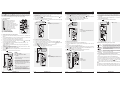
3. Gerätebeschreibung
500V
250V 1000V
PV 2
DIN EN 62446 (VDE 0126-23), DIN EN 61829 (VDE 0126-24)
Auto Mode
a Vo/c, Is/c, MΩ
b Vmpp, Impp, FF
c a + b
d
Auto
Ω
NULL
RPE
Mode
RISO
VISO
5
%
NULL
1 LCD-Display
2 RPE -Taste, Prüfung des Schutzleiters
3 Auto -Taste, automatischer Prüfablauf
4 RISO -Taste, Isolationsprüfung (2-polig)
5 Mode -Taste, Auswahl Prüfablauf
6 Ω
NULL -Taste, Nullabgleich der Messleitung
7 V
ISO -Taste, Auswahl ISO-Prüfspannung
8 -Taste, Messwerte aufrufen
9 1-Taste, Umschaltung LCD-Display
J -Taste, Messwerte speichern
K
+ PV-Prüfbuchse (rot)
L
– PV-Prüfbuchse (schwarz)
M – 4 mm Prüfbuchse (schwarz)
N + 4 mm Prüfbuchse (rot)
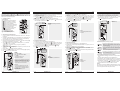
4. Auto-Messung des PV-Generators
1. Lesen und verstehen Sie alle Sicherheitshinweise unter Punkt 1. „Wichtige In-
formationen“.
2. Schließen Sie das BENNING PV 2, wie dargestellt, an den PV-Generator an.
Verwenden Sie dazu die PV-Messleitungen und die rote 4 mm Messleitung.
3. Die Leerlaufspannung (Vo/c) wird automatisch angezeigt.
4. Bei falscher Spannungspolarität wird das Symbol auf dem LCD-Display 1
eingeblendet und die Messung wird gesperrt.
5. Über die Mode -Taste 5 den gewünschten Prüfablauf (Mode a - d) anwählen:
a0HVVXQJYRQ9RF,VFXQG0ȍ
b Messung der I-U Kennlinie mit Vmpp, Impp und FF (Füllfaktor)
c Messung von a + b
d Messung über AC/DC Stromzange
6. Wählen Sie über die V
ISO -Taste 7 eine ISO-Prüfspannung von 250 V, 500 V oder
1000 V an.
7. Drücken Sie die Auto -Taste 3 zum Start des Prüfablaufs.
8. Sobald der Prüfablauf beendet ist, wird „Store?“ im LCD-Display 1 angezeigt.
9. Die -Taste J speichert die Messwerte.
500V
250V 1000V
PV 2
DIN EN 62446 (VDE 0126-23), DIN EN 61829 (VDE 0126-24)
Auto Mode
a Vo/c, Is/c, MΩ
b Vmpp, Impp, FF
c a + b
d
Auto
Ω
NULL
RPE
Mode
RISO
VISO
NULL
rot rot
schwarz
mc
Uoc x Isc 10 kW
Max.: Isc = 15 A, Uoc = 1000 V,
P = 10 kW
PV-Generator allpolig vom
Wechselrichter trennen!
Messung nur am einzelnen PV-Strang! Bei
parallel geschalteten PV-Strängen addieren
sich die Kurzschlussströme und können
zusätzlich durch vorhandene Kapazitäten
des PV-Generators erhöht werden.
Hinweis:
Die rote 4 mm Messleitung wird für die
Isolationswiderstandsmessung benötigt.
Die Messung der I-U Kennlinie erfordert
eine vorherige Kopplung zum
BENNING SUN 2.
02/ 2021
BENNING PV 2
502/ 2021
BENNING PV 2
402/ 2021
BENNING PV 2
302/ 2021
BENNING PV 2
2
DDDD

Short Instructions
BENNING PV 2
1. Important information
m
Before using the BENNING PV 2 please read the detailed operating
manual (http://tms.benning.de/pv2) carefully.
The BENNING PV 2 should only be used by suitably trained per-
sonnel.
cThe connection to the PV generator is made exclusively in ac-
cordance with the connection figure of the operating manual.
Disconnect not required tests leads from the BENNING PV 2.
c
Before the measurement disconnected the PV array from the PV inverter!
The PV string under test must not exceed the maximum open-circuit
voltage of 1000 V, the maximum short-circuit current of 15 A and the
maximum DC power (P = Uoc x Isc) of 10 kW.
The measurements are to be carried out on the individual PV string!
It must be ensured that all switching devices and isolating devices are
open and that all PV strings are isolated from each other.
Only test a single PV string, never test multiple strings and beware of
parallel connections! High levels of capacitance within the circuit under
test can cause high currents to flow and may damage the test instru-
ment.
Non-observiance will result in damage to the BENNING PV 2!
cDisconnect the BENNING PV 2 from the test sample directly after
the test.
cDo not touch the measuring probes! During insulating resistance
measurements, high electric currents might be applied to the
measuring probes.
cDo not touch any metal parts of the test object during measure-
ment.
cThe PV generator must be isolated from the electric power supply!
Neither the positive nor the negative pole of the PV generator must
be earthed!
c
Via the 4 mm test leads, voltage measurements on mains supply
circuits are possible. Via the 4 mm test sockets, the BENNING PV 2
must be used only in electric circuits of overvoltage category III
with max. 300 V AC/DC for phase-to-earth measurements. For this
please disconnect the PV 2 PV measuring leads from the PV test
sockets before measuring.
cBefore starting the unit, always check it for signs of damage. Do not
use a damaged BENNING PV 2!
mOnly use measuring leads, which are supplied with the
BENNING PV 2.
cThe BENNING PV 2 is intended for making measurements under dry
ambient conditions only.
16. Error codes
Error code Remedy
The internal fuse has blown. Refer to chapter 9.5
in the opera ting instructions for details.
The electronic components of the BENNING PV 2
have reached the maximum admissible tempera-
ture. Disconnect the BENNING PV 2 from the ob-
ject to be measured and let it cool down.
The DC short-circuit current has the maximum va-
lue of 15 A. The measurement has been stopped.
The DC open circuit voltage has exceeded the
maximum value of 1000 V. The measurement has
been stopped.
The DC power has exceeded the maximum value
of 10 kW. Measurement has been cancelled.
Immediately disconnect the BENNING PV 2 from
the PV generator!
Please return the BENNING PV 2 to an authorized
service center, see chapter 9.6 „Calibration“ for
the address.
Please return the BENNING PV 2 to an authorized
service center, see chapter 9.6 „Calibration“ for
the address.
Please return the BENNING PV 2 to an authorized
service center, see chapter 9.6 „Calibration“ for
the address.
or
Please return the BENNING PV 2 to an authorized
service center, see chapter 9.6 „Calibration“ for
the address.
etc.
Please return the BENNING PV 2 to an authorized
service center, see chapter 9.6 „Calibration“ for
the address.
The BENNING PV 2 is not correctly calibrated,
see chapter 9.6 „Calibration“.
Storage has failed. Please store the measured va-
lues again to the next storage location available.
Storage to the NFC chip has failed. Please remove
the NFC-enabled device from the BENNING PV 2.
Other error codes see detailed user guide (http://tms.benning.de/pv2).
17. Optional accessories
PC software BENNING SOLAR Manager (part no. 050423)
Temperature sensor with suction cup for BENNING SUN 2 (part no. 050424)
PV module holder for BENNING SUN 2 (part no. 050425)
Current clamp adapters BENNING CC 3 (part no. 044038)
Measuring lead BENNING TA 5, length 40 m (part no. 044039)
500V
250V 1000V
PV 2
DIN EN 62446 (VDE 0126-23), DIN EN 61829 (VDE 0126-24)
Auto Mode
a Vo/c, Is/c, MΩ
b Vmpp, Impp, FF
c a + b
d
Auto
Ω
NULL
RPE
Mode
RISO
VISO
14. Measuring ranges and limiting values
Function Range
RPE/V ȍȍ99$&'&
RISO (2-pin) 0ȍ0ȍ
Vo/c 5 V - 1000 V DC
Is/c 0.5 A - 20 A DC
RISO (AUTO measurement) 0ȍ0ȍ
I 0.1 A - 40 A AC/DC
ISO test voltage Limiting value of
insulating resistance
250 V 0ȍ
500 V/ 1000 V 0ȍ
15. Setting the date and time
1. Turn off the BENNING PV 2.
2. Press and hold the
-
key
8 and then press simultaneously the RISO -key 4 and
the Mode -key 5 of BENNING PV 2.
3. The date format and time format is shown as follows:
MM.DD = month (1-12). Day (1-31)
YYYY = year
HH.mm = hours (0-23).minutes (0-59)
SS = seconds (0-59)
4. Press the RPE -key 2 to select a date field and time field
5. A blinking field shows that this field can be set.
6. With the -key J and the
-
key
8, the value increases or decreases. With
each change, the second field is set to zero.
7. Turn off the device to save the setting.
Note:
If the BENNING PV 2 has established a radio connection to the BENNING SUN 2,
the date/ time of the BENNING PV 2 will be synchronized automatically after 10
seconds to the date/ time of the BENNING SUN 2, if the device detects a deviation
RIPRUHWKDQPLQXWH%(11,1*681PDVWHUĺ%(11,1*39VODYH
12. Radio connection to the BENNING SUN 2
The BENNING PV 2 is able to receive the measured values (insolation, PV module /
ambient temperature and date / time stamp) of the optional BENNING SUN 2 (part
no. 050420) via radio connection.
Typical radio range in open space: approx. 30 m
Coupling with BENNING SUN 2
1. Remove all electronic devices in direct vicinity
2. Switch the BENNING PV 2 and the BENNING SUN 2 off.
3. Press and hold the two ON/OFF keys of the BENNING SUN 2.
4. Press and simultaneously hold the RISO -key 4 and the Mode -key 5 of the
BENNING PV 2.
5. The BENNING PV 2 indicates the successful coupling by means of an acoustic
signal and by displaying the serial no. of the BENNING SUN 2
6. The “W/m2” symbol is shown on the LC display 1 of the BENNING PV 2.
Decoupling from BENNING SUN 2
1. Remove all electronic devices in direct vicinity.
2. Switch the BENNING PV 2 off.
3. Press and hold the RISO -key 4 and the Mode -key 5 of the BENNING PV 2 for ap-
prox. 10 seconds.
4. The BENNING PV 2 indicates the decoupling from the BENNING SUN 2 by
means of an acoustic signal and by clearing the LC display.
5. The “RPEȍ´V\PEROLVVKRZQRQWKH/&GLVSOD\1 of the BENNING PV 2.
Activating/deactivating the radio transmission of the BENNING SUN 2
1. Couple the BENNING PV 2 with the BENNING SUN 2.
2. To activate/deactivate the radio transmission, press and hold the -key of the
BENNING SUN 2 and simultaneously press the -key. A flashing triangle
is shown on the LC display.
3. The BENNING PV 2 receives the measured values as soon as the insolation
(W/m²) is shown on the LC display 1.
4. AUTO measurement (modes a - c) additional stores the temperature values
and the date/time stamp of the BENNING SUN 2.
5. If the BENNING PV 2 is outside the radio range of the BENNING SUN 2, the “W/
m2” on the LC display 1 starts flashing. Moreover, “_ _ _ _” is shown on the LC
display, if the measured insolation value is outside the measuring range.
Note:
If the BENNING PV 2 does not receive any radio signal from the BENNING SUN 2, the
display indications are stored with the date/time stamp of the BENNING PV 2.
13. Representing the I-V characteristic via the “BENNING PV Link” app
Requirements: NFC-enabled Android device
The app allows the user to represent and to compare the measured I-V characte-
ristic and the power characteristic with the nominal module data of the manufacturer
under STC conditions.
Please read the detailed operating manual of the BENNING PV 2 and of the
³%(11,1*39/LQN´¿UVWKWWSWPVEHQQLQJGHSY
1. The NFC chip required for this functionality is located under the NFC logo on the
top of the BENNING PV 2 housing.
2. Upon completion of each test procedure (modes b + c) as well as after calling
a storage location via the -key 8 and pressing the 1-key 9, the I-V charac-
teristic is written to the NFC chip.
3. The I-V characteristic can be read and represented via an Android device with
NFC functionality.
02/ 2021
BENNING PV 2
102/ 2021
BENNING PV 2
802/ 2021
BENNING PV 2
702/ 2021
BENNING PV 2
6
tttt

9. AC/DC voltage measurement
1. Disconnect the PV measuring leads from the BENNING PV 2.
2. Connect the red and black safety measuring lead as pictured.
3. The BENNING PV 2 automatically measures the AC/DC voltage at the measu-
ring probes.
4. The polarity of the DC voltage is displayed by “+/-“. In case of AC voltage, “+/-“
will be displayed alternately.
5. Press the -key J to store the measured values.
500V
250V 1000V
PV 2
DIN EN 62446 (VDE 0126-23), DIN EN 61829 (VDE 0126-24)
Auto Mode
a Vo/c, Is/c, MΩ
b Vmpp, Impp, FF
c a + b
d
Auto
Ω
NULL
RPE
Mode
RISO
VISO
NULL
Max.
CAT III 400 VQ
10. Measured value memory (999 display screens)
-Store Store all measurements currently on the LC display. In the RE-
CALL mode, the measuring results are called in reverse order.
-Recall Recall the stored measured values on the LC display. Press
and hold to send the measured value memory to the USB port.
1 + Clear all results from memory.
1 +Display Switch-over of the LC display in the I-V characteristics mode
from Vo/c, Is/c to Vmpp, Impp.
11. Downloading the measured value memory to the PC
1. Install the BENNING SOLAR data logger and driver from http://tms.benning.de/
pv2.
2. Disconnect all measuring leads from the BENNING PV 2.
3. Connect the BENNING PV 2 to your PC by means of the USB connecting cable.
4. Start the PC software, select the COM port and click “Download”.
5. Switch on the BENNING PV 2, press the -key 8 and hold the -key 8
again for approx. 2 seconds to start the download.
6. Open the measured value file in the CSV format via MS Excel®.
Note:
The optional PC software BENNING SOLAR Manager (part no. 050423) allows
documentation according to DIN EN 62446 (VDE 0126-23) as well as representa-
tion of the I-V characteristic according to DIN EN 61829 (VDE 0126-24).
7. Insulating resistance (RISO, 2-pin)
1. Connect the 4 mm measuring leads as shown in the figure.
2. Press the V
ISO -key 7 to select an ISO testing voltage of 250 V, 500 V or 1.000 V.
3. For single measurement (2 sec.), press and release the RISO
-key 4
.
For continuous measurement, press and hold the RISO
-key 4
for several seconds
until the symbol is shown on the LC display 1.
4. Press the RISO
-key 4
to terminate the continuous measurement.
5. Press the -key J to store the measured values.
PV-module/ -string
500V
250V 1000V
PV 2
DIN EN 62446 (VDE 0126-23), DIN EN 61829 (VDE 0126-24)
Auto Mode
a Vo/c, Is/c, MΩ
b Vmpp, Impp, FF
c a + b
d
Auto
Ω
NULL
RPE
Mode
RISO
VISO
red
black
Option:
40 m measuring leads BENNING TA 5
part no. 044039
8. AC/DC current measurement
1. Disconnect all measuring leads from the BENNING PV 2.
2. Connect the BENNING CC 3 (option) current clamp adapter to the 4 mm test
sockets.
3. Select the 40 A range on the BENNING CC 3.
4. Press the null balance key (ZERO) of the BENNING CC 3 for approx. 2 seconds.
5. Press the Mode -key 5 to select the desired mode d of the BENNING PV 2. The
symbol is shown on the LC display 1.
6. The AC/DC current can be measured in single-wire live conductor.
7. Press the -key J to store the measured values.
500V
250V 1000V
PV 2
DIN EN 62446 (VDE 0126-23), DIN EN 61829 (VDE 0126-24)
Auto Mode
a Vo/c, Is/c, MΩ
b Vmpp, Impp, FF
c a + b
d
Auto
Ω
NULL
RPE
Mode
RISO
VISO
+
40A : 10mV/A
300A : 1mV/A
BATT
LOW
PWR
ON
BENNING CC 3
ZERO A
OFF
40A
300A
CAT. III 600V
300A
Option:
BENNING CC 3
part no. 044038
5. Null balance of the measuring leads, resistance (RPE)
1. Connect the measuring leads to the red and black 4 mm test sockets of the
BENNING PV 2.
2. Short-circuit the probe tips via the alligator clips.
3. Press and hold the Ω
NULL -key 6 until an acoustic signal sounds and the
Ω
NULL -sym-
bol is displayed 1.
4. The Null-value is stored when unit is switched off.
5. To disable, press Ω
NULL -key 6 until the
Ω
NULL -symbol is removed from LC display 1.
500V
250V 1000V
PV 2
DIN EN 62446 (VDE 0126-23), DIN EN 61829 (VDE 0126-24)
Auto Mode
a Vo/c, Is/c, MΩ
b Vmpp, Impp, FF
c a + b
d
Auto
Ω
NULL
RPE
Mode
RISO
VISO
NULL
red black Note:
Max. measuring lead resistance:
10 Ohm
6. Protective conductor resistance (RPE)
1. Connect the 4 mm measuring leads as shown.
2. To make a single measurement (2 sec.), press and release the RPE -key 2.
3. To make a continuous measurement, press and hold the RPE -key 2 until the
symbol is displayed 1 continuously.
4. Press the RPE -key 2 to terminate the continuous measurement.
5. Press the -key J to store the measured values.
500V
250V 1000V
PV 2
DIN EN 62446 (VDE 0126-23), DIN EN 61829 (VDE 0126-24)
Auto Mode
a Vo/c, Is/c, MΩ
b Vmpp, Impp, FF
c a + b
d
Auto
Ω
NULL
RPE
Mode
RISO
VISO
NULL
RPE red
black
PV-module/ -string
Option:
40 m measuring leads BENNING TA 5
part no. 044039
2. Switching the device ON/OFF
Press the RISO -key 4 and the Mode
-
key 5 simultaneously to switch the device ON or
OFF. Without pressing a key, the device switches OFF automatically after approx. 1
minute (APO, Auto Power-Off). The switch-off time can be set within a range from 1
min. to 10 min. (see operating manual on http://tms.benning.de/pv2).
3. Device description
500V
250V 1000V
PV 2
DIN EN 62446 (VDE 0126-23), DIN EN 61829 (VDE 0126-24)
Auto Mode
a Vo/c, Is/c, MΩ
b Vmpp, Impp, FF
c a + b
d
Auto
Ω
NULL
RPE
Mode
RISO
VISO
5
%
NULL
1 LC Display
2 RPE key, protective conductor test
3 Auto -key, automatic test procedure
4 RISO -key, insulation test (2-pin)
5 Mode -key, selecting the test procedures
6 Ω
NULL -key, null balance of the measuring line
7 V
ISO -key, selecting the ISO testing voltage
8 -key, calling measured values
9 1-key, switch-over of LC display
J -Taste, storing measured values
K
+ PV test socket (red)
L
– PV test socket (black)
M – 4 mm test socket (black)
N + 4 mm test socket (red)
4. AUTO measurement of the PV generator
1. Carefully read and understand all safety notes under point 1. “Important infor-
mation”.
2. Connect the BENNING PV 2 to the PV generator as shown, by means of the
enclosed PV measuring leads and the red 4 mm test lead.
3. The open-circuit voltage (Vo/c) is automatically displayed.
4. In case of reversed polarity of the DC voltage, the symbol is displayed 1
and the measurement will be blocked.
5. Press the Mode -key 5 to select the desired test procedure (modes a - d):
a0HDVXULQJ9RF,VFDQG0ȍ
b Measuring the I-V characteristic with Vmpp, Impp and FF (filling factor)
c Measuring a + b
d Measuring via AC/DC current clamp
6. Press the V
ISO -key 7 to select an ISO testing voltage of 250 V, 500 V or 1.000 V.
7. Press the Auto -key 3 to start the test procedure.
8. As soon as the test procedure is completed, “Store?” will be indicated on the LC
display 1.
9. Press the -key J to store the measured values.
500V
250V 1000V
PV 2
DIN EN 62446 (VDE 0126-23), DIN EN 61829 (VDE 0126-24)
Auto Mode
a Vo/c, Is/c, MΩ
b Vmpp, Impp, FF
c a + b
d
Auto
Ω
NULL
RPE
Mode
RISO
VISO
NULL
red red
black
PV-module/ -string mc
Uoc x Isc 10 kW
Max.: Isc = 15 A, Uoc = 1000 V,
P = 10 kW
Disconnect all poles of the PV array from the
inverter before testing!
Only test a single PV string, never test multiple
strings and beware of parallel connections!
High levels of capacitance within the circuit
under test can cause high currents to flow and
may damage the test instrument.
Note:
The red 4 mm measuring lead is required for
the insulation resistance measurement.
Measurement of the I-V characteristic requires
previous coupling to the BENNING SUN 2.
02/ 2021
BENNING PV 2
502/ 2021
BENNING PV 2
402/ 2021
BENNING PV 2
302/ 2021
BENNING PV 2
2
tttt

Mode d’emploi abrégé
BENNING PV 2
1. Informations importantes
m
Lisez le mode d’emploi détaillé complètement (http://tms.benning.de/pv2, dans les
langues allemand, anglais) avant d’utiliser l’appareil BENNING PV 2.
L’appareil BENNING PV 2 ne doit être utilisé que par du personnel spécialiste
ayant reçu la formation correspondante.
c
Le raccordement au générateur photovoltaïque ne doit être effectué que confor-
mément aux schémas de connexion contenus dans le mode d’emploi.
Les câbles de mesure non requis doivent être déconnectés de l’appareil BENNING
PV 2.
c
Avant la mesure, déconnectez tous les pôles du générateur PV de l’onduleur PV!
Le générateur photovoltaïque ou le string photovoltaïque ne doit pas dépasser
la tension en circuit ouvert maximale de 1000 V DC ainsi que le courant de court-
circuit maximal de 15 A et la puissance maximale continue de 10 kW pas dépasser
(P = Uoc x Isc).
Les mesures doivent être effectuées sur la string PV individuelle!
Il faut s’assurer que tous les appareils de commutation et les dispositifs d’iso-
lement sont ouverts et que toutes les chaînes photovoltaïques sont isolées les
unes des autres.
Ne testez qu’une seule string photovoltaïque, ne testez jamais plusieurs strings
et méfiez-vous des connexions parallèles! Des niveaux élevés de capacité dans le
circuit testé peuvent provoquer des courants élevés et endommager l’instrument
de test.
Le non-respect entraînera des dommages au BENNING PV 2!
cDéconnectez l’appareil BENNING PV 2 du générateur photovoltaïque juste après
que le contrôle soit fini.
cNe touchez pas les pointes de mesure ! Lors des mesures de la résistance d’iso-
lement, des tensions électriques très hautes peuvent être présentes aux pointes
de mesure.
cNe touchez pas des pièces métalliques de l’objet de contrôle pendant la mesure.
c
Le générateur photovoltaïque doit être isolé de l’alimentation électrique principale !
Il ne faut pas mettre à la terre ni le pôle positif ni le pôle négatif du générateur
photovoltaïque !
c
Les câbles de mesure de 4 mm permettent d’effectuer des mesures de tension aux
circuit électriques de prises de courant. Au moyen des douilles de test de 4 mm,
l’appareil BENNING PV 2 ne doit être utilisé que pour les circuits électriques de la
catégorie de surtension III avec des conducteurs de 300 V AC/DC max. par rapport
à la terre. Pour cela, il est nécessaire de déconnecter auparavant les câbles de
mesure photovoltaïques des douilles de test photovoltaïques.
cAssurez-vous, avant chaque mise en marche, que l’appareil et les câbles ne sont
pas endommagés. N’utilisez jamais un appareil endommagé !
mN’utilisez que les câbles de mesure inclus dans le contenu de l’emballage de
l’appareil BENNING PV 2.
cL’appareil BENNING PV 2 n’est conçu qu’afin d’effectuer des mesures dans un
environnement sec.
16. Codes d’erreur
Codes d’erreur Remède
Fusible interne défectueux -> voir chapitre 9.5 du
mode d‘emploi détaillé.
Les composants électroniques de l‘appa-
reil BENNING PV 2 ont atteint la température
maximale admissible. Déconnectez l‘appareil
BENNING PV 2 de l‘objet à mesurer et laissez-le
refroidir.
Le courant de court-circuit DC a dépassé la valeur
maximale de 15 A. La mesure a été interrompue.
La tension continue de circuit ouvert a dépassé
la valeur maximale de 1000 V. La mesure a été
interrompue.
La puissance DC a dépassée la valeur maximale
de 10 kW. La mesure a été annulée.
Déconnectez immédiatement l’appareil
%(11,1*39GXJpQpUDWHXUSKRWRYROWDȧTXH
Veuillez retourner l’appareil BENNING PV 2 à
un point de service autorisé (voir le chapitre 9.6
« Etalonnage » pour l’adresse).
Veuillez retourner l’appareil BENNING PV 2 à
un point de service autorisé (voir le chapitre 9.6
« Etalonnage » pour l’adresse).
Veuillez retourner l’appareil BENNING PV 2 à
un point de service autorisé (voir le chapitre 9.6
« Etalonnage » pour l’adresse).
or
Veuillez retourner l’appareil BENNING PV 2 à
un point de service autorisé (voir le chapitre 9.6
« Etalonnage » pour l’adresse).
etc.
Veuillez retourner l’appareil BENNING PV 2 à
un point de service autorisé (voir le chapitre 9.6
« Etalonnage » pour l’adresse).
Le BENNING PV 2 n‘est pas correctement calibré
(voir le chapitre 9.6 « Etalonnage »).
L‘enregistrement a échoué. Veuillez enregistrer
les valeurs mesurées de nouveau au prochain
emplacement de mémoire disponible.
L‘enregistrement sur la puce NFC a échoué.
Veuillez enlever l‘appareil compatible NFC de
l‘appareil BENNING PV 2.
Autres codes d’erreur voir mode d’emploi détaillé (http://tms.benning.de/pv2).
17. Optional accessories
Logiciel PC BENNING SOLAR Manager (TN 050423)
Capteur de température à ventouse pour BENNING SUN 2 (TN 050424)
Support de module PV pour BENNING SUN 2 (TN 050425)
Adaptateur à pince électrique BENNING CC 3 (TN 044038)
40 m Câble de mesure BENNING TA 5 (TN 044039)
500V
250V 1000V
PV 2
DIN EN 62446 (VDE 0126-23), DIN EN 61829 (VDE 0126-24)
Auto Mode
a Vo/c, Is/c, MΩ
b Vmpp, Impp, FF
c a + b
d
Auto
Ω
NULL
RPE
Mode
RISO
VISO
14. Plages de mesure et valeurs limites
Fonction Plage
RPE/V ȍȍ99$&'&
RISO (à 2 broches) 0ȍ0ȍ
Vo/c 5 V - 1000 V DC
Is/c 0,5 A - 20 A DC
RISO (mesure « AUTO ») 0ȍ0ȍ
I 0,1 A - 40 A AC/DC
Tension de contrôle d'isolement Valeur limite de la
résistance d'isolement
250 V 0ȍ
500 V/ 1000 V 0ȍ
15. Réglage de la date et de l’heure
1. Éteignez le BENNING PV 2.
2. Appuyez et maintenez enfoncé le bouton 8 et appuyez sur la même le RISO
bouton 4 et le Mode bouton 5 sur le BENNING PV 2.
3. Le format de date et de format de l’heure est indiquée comme suit:
MM.DD = mois (1-12).jour (1-31)
YYYY = année
HH.mm = heures (0-23). procès-verbal (0-59)
SS = seconde (0-59)
4. Appuyez sur le bouton RPE 2 pour sélectionner un champ date et champ de
l’heure.
5. Un symbole clignotant indique que ce champ peut être défini.
6. Avec la touche J et la touche 8, la valeur augmente ou diminue. A
chaque changement, le champ des secondes est remis à zéro.
7. Eteignez l’appareil pour enregistrer le réglage.
Remarque :
Au cas où l’appareil BENNING PV 2 aurait établi une liaison radioélectrique avec
l’appareil BENNING SUN 2, la date et l’heure de l’appareil BENNING PV 2 seront
synchronisées automatiquement à la date et l’heure de l’appareil BENNING SUN 2
après 10 secondes, si une déviation supérieure à 1 minute est détectée. BENNING
681PDvWUHĺ%(11,1*39HVFODYH
12. Liaison radio vers l’appareil BENNING SUN 2
L’appareil BENNING PV 2 peut recevoir par radio les valeurs mesurées (ensoleil-
lement, température du module photovoltaïque / température ambiante et horoda-
teur) de l’appareil BENNING SUN 2 (réf. 050420) en option.
Portée radio typique sur le terrain en plein air : 30 m environ
Couplage à l’appareil BENNING SUN 2
1. Enlevez tous les appareils électroniques à proximité.
2. Eteignez les appareils BENNING PV 2 et BENNING SUN 2.
3.
Maintenez appuyées les deux touches « ON/OFF » de l’appareil BENNING SUN 2.
4. Maintenez appuyées en même temps les touches RISO 4 et Mode 5 de l’appareil
BENNING PV 2.
5. L’appareil BENNING PV 2 indique un couplage réussi en émettant un signal
acoustique et en affichant le numéro série de l’appareil BENNING SUN 2.
6. Le symbole « W/m2 » est affiché sur l’afficheur à cristaux liquides 1 de l’appa-
reil BENNING PV 2.
Découplage de l’appareil BENNING SUN 2
1. Enlevez tous les appareils électroniques à proximité.
2. Eteignez l’appareil BENNING PV 2.
3. Maintenez appuyées les touches RISO 4 et Mode 5 de l’appareil BENNING PV 2
pour 10 secondes environ.
4. L’appareil BENNING PV 2 indique le découplage de l’appareil BENNING SUN 2
en émettant un signal acoustique et en effaçant l’afficheur à cristaux liquides.
5. Le symbole « RPEȍªHVWDIILFKpVXUO¶DIILFKHXUjFULVWDX[OLTXLGHV1 de l’appa-
reil BENNING PV 2.
Activer/désactiver la transmission radio de l’appareil BENNING SUN 2
1. Couplez l’appareil BENNING PV 2 à l’appareil BENNING SUN 2.
2. Afin d’activer/de désactiver la transmission radio, maintenez appuyée la touche
de de l’appareil BENNING SUN 2 et appuyez sur la touche en même
temps. Un triangle clignotant est affiché sur l’écran à cristaux liquides.
3. L’appareil BENNING PV 2 reçoit les valeurs mesurées dès que l’ensoleillement
(W/m²) est affiché sur l’écran à cristaux liquides 1.
4. Lors d’une mesure « AUTO » (modes a - c), les températures et l’horodateur
de l’appareil BENNING SUN 2 sont également enregistrés.
5. Quand l’appareil BENNING PV 2 se trouve hors de la portée radio de l’appareil
BENNING SUN 2, le symbole « W/m2 » commence à clignoter sur ‘afficheur
à cristaux liquides 1. En plus, « _ _ _ _ » est affiché sur l’afficheur à cristaux
liquides, si la valeur mesurée d’ensoleillement est hors de la plage de mesure.
Remarque :
Au cas où l’appareil BENNING PV 2 ne recevrait pas de signal radio de l’appareil
BENNING SUN 2, les affichages sont enregistrés avec l’horodateur de l’appareil
BENNING PV 2.
13. Représentation de la caractéristique IU au moyen de l’appli « BENNING PV Link »
Condition : Appareil Android compatible NFC
L’appli permet de représenter et de comparer la caractéristique IU mesurée et la
caractéristique de puissance aux données nominales du module indiquées par le
fabricant pour les conditions de test standards (angl. : « STC »).
Lisez d’abord le mode d’emploi détaillé de l’appareil BENNING PV 2 et de l’appli
« BENNING PV Link » (http://tms.benning.de/pv2).
1. La puce NFC se trouve sous le logo NFC sur la partie supérieure du boîtier de
l’appareil BENNING PV 2.
2. Après chaque procédure de test (modes b + c) ainsi qu’après avoir appelé un
emplacement de mémoire via la touche 8 et appuyé sur la touche 1 9, la
caractéristique IU est enregistrée sur la puce NFC.
3. La caractéristique IU peut être lue et visualisée au moyen d’un appareil Android
avec fonctionnalité NFC.
02/ 2021
BENNING PV 2
102/ 2021
BENNING PV 2
802/ 2021
BENNING PV 2
702/ 2021
BENNING PV 2
6
FFFF

9. Mesure de tension AC/DC
1.
Enlevez tous les câbles de mesure photovoltaïques de l’appareil BENNING PV 2.
2. Raccordez les câbles de mesure de sécurité de 4 mm comme démontré.
3. L’appareil BENNING PV 2 mesure automatiquement la tension AC/DC aux
pointes de mesure.
4. La polarité de la tension continue (DC) est marquée par les symboles « +/- ».
En cas d’une tension alternative (AC), les symboles « +/- » sont affichés de
manière alternante.
5. Appuyez sur la touche J afin d’enregistrer les valeurs mesurées.
500V
250V 1000V
PV 2
DIN EN 62446 (VDE 0126-23), DIN EN 61829 (VDE 0126-24)
Auto Mode
a Vo/c, Is/c, MΩ
b Vmpp, Impp, FF
c a + b
d
Auto
Ω
NULL
RPE
Mode
RISO
VISO
NULL
Max.
CAT III 400 VQ
10. Mémoire de valeurs mesurées (999 emplacements de mémoire)
-Store
6HUWjHQUHJLVWUHUWRXVOHVUpVXOWDWVGHPHVXUHDႈFKpVVXUO¶DI-
¿FKHXUjFULVWDX[OLTXLGHV(QPRGH©5(&$//ªOHVUpVXOWDWV
de mesure sont appelés dans l‘ordre inverse.
-Recall
$SSHOHU OHV UpVXOWDWV GH PHVXUH HQUHJLVWUpV VXU O¶DႈFKHXU j
FULVWDX[OLTXLGHV0DLQWHQH]DSSX\pHODWRXFKHD¿QG¶HQYR\HU
la mémoire de valeurs mesurées au port USB.
1 + (ႇDFHUODPpPRLUHHQWLqUHGHYDOHXUVPHVXUpHV
1 +Display Commutation de l’écran à cristaux liquides en mode « Caracté-
ristiques IU » de Vo/c, Is/c à Vmpp, Impp.
11. Téléchargement de la mémoire de valeurs mesurées sur votre PC
1. Installez le BENNING SOLAR Datalogger et le pilote à partir du http://tms.
benning.de/pv2.
2. Enlevez tous les câbles de mesure de l’appareil BENNING PV 2.
3. Raccordez l’appareil BENNING PV 2 à votre PC au moyen d’un câble de rac-
cordement USB.
4. Lancez le logiciel PC de téléchargement, sélectionnez le port COM et cliquez
sur « Download » (« Téléchargement »).
5. Allumez l’appareil BENNING PV 2, appuyez sur la touche 8 et maintenez
appuyée de nouveau la touche 8 pour 2 secondes environ afin de lancer le
téléchargement.
6. Ouvrez le fichier des valeurs mesurées au format CSV via MS Excel®.
Remarque :
Le logiciel PC en option BENNING SOLAR Manager (réf. 050423) permet la docu-
mentation conformément à DIN EN 62446 (VDE 0126-23) ainsi que la représenta-
tion de la caractéristique IU conformément à DIN EN 61829 (VDE 0126-24).
7. Résistance d’isolement (RISO, à 2 broches)
1. Raccordez les câbles de mesure de 4 mm comme démontré.
2. Appuyez sur la touche V
ISO 7 afin de sélectionner une tension de contrôle d’iso-
lement de 250 V, 500 V ou 1000 V.
3. Afin d’effectuer une mesure individuelle (2 secondes), appuyez sur la touche
RISO
4
et lâchez-la. Afin d’effectuer une mesure continue, maintenez appuyée la
touche RISO
4
pour quelques secondes jusqu’à ce que le symbole soit affiché
sur l’écran à cristaux liquides 1.
4. Appuyez sur la touche RISO
4
afin de terminer la mesure continue.
5. Appuyez sur la touche J afin d’enregistrer les valeurs mesurées.
Module PV/ string
500V
250V 1000V
PV 2
DIN EN 62446 (VDE 0126-23), DIN EN 61829 (VDE 0126-24)
Auto Mode
a Vo/c, Is/c, MΩ
b Vmpp, Impp, FF
c a + b
d
Auto
Ω
NULL
RPE
Mode
RISO
VISO
rouge
noir
Option:
40 m Câble de mesure BENNING TA 5
TN 044039
8. Mesure de courant AC/DC
1. Enlevez tous les câbles de mesure de l’appareil BENNING PV 2.
2. Raccordez l’adaptateur à pince électrique BENNING CC 3 (Option) aux douilles
de test de 4 mm.
3. Sélectionnez la plage de 40 A sur l’appareil BENNING CC 3.
4. Appuyez pour 2 secondes sur la touche de compensation à zéro (ZERO) de
l’appareil BENNING CC 3.
5. Appuyez sur la touche Mode 5 afin de sélectionner le mode d sur l’appareil
BENNING PV 2. Le symbole s’affiche sur l’écran à cristaux liquides 1.
6. Le courant AC/DC peut être mesuré aux conducteurs unipolaires sous tension.
7. Appuyez sur la touche J afin d’enregistrer les valeurs mesurées.
500V
250V 1000V
PV 2
DIN EN 62446 (VDE 0126-23), DIN EN 61829 (VDE 0126-24)
Auto Mode
a Vo/c, Is/c, MΩ
b Vmpp, Impp, FF
c a + b
d
Auto
Ω
NULL
RPE
Mode
RISO
VISO
+
40A : 10mV/A
300A : 1mV/A
BATT
LOW
PWR
ON
BENNING CC 3
ZERO A
OFF
40A
300A
CAT. III 600V
300A
Option:
BENNING CC 3
TN 044038
5. Compensation à zéro des câbles de mesure, résistance PE (RPE)
1. Raccordez les câbles de mesure aux douilles de test de 4 mm rouges et noirs
de l‘appareil BENNING PV 2.
2. Court-circuitez les pointes d’essai au moyen des pinces crocodiles.
3. Maintenez appuyée la touche Ω
NULL 6 jusqu‘à ce que un signal acoustique soit
émis et le symbole
Ω
NULL soit affiché sur l‘afficheur à cristaux liquides 1.
4. La valeur zéro sera enregistrée quand l‘appareil est mis en arrêt.
5. Pour une désactivation, appuyez sur la touche Ω
NULL 6 jusqu‘à ce que le symbole
Ω
NULL disparaisse de l‘afficheur à cristaux liquides 1.
500V
250V 1000V
PV 2
DIN EN 62446 (VDE 0126-23), DIN EN 61829 (VDE 0126-24)
Auto Mode
a Vo/c, Is/c, MΩ
b Vmpp, Impp, FF
c a + b
d
Auto
Ω
NULL
RPE
Mode
RISO
VISO
NULL
rouge noir Remarque:
Résistance maximale du câble
de mesure : 10 ohms
6. Résistance du conducteur de protection (RPE)
1. Raccordez les câbles de mesure de 4 mm comme démontré.
2. Afin d’effectuer une mesure individuelle (2 secondes), appuyez sur la touche RPE
2 et lâchez-la.
3. Afin d’effectuer une mesure continue, maintenez appuyée la touche RPE 2pour
quelques secondes jusqu’à ce que le symbole soit affiché sur l’afficheur à
cristaux liquides 1.
4. Appuyez sur la touche RPE 2 afin de terminer la mesure continue.
5. Appuyez sur la touche J afin d’enregistrer les valeurs mesurées.
500V
250V 1000V
PV 2
DIN EN 62446 (VDE 0126-23), DIN EN 61829 (VDE 0126-24)
Auto Mode
a Vo/c, Is/c, MΩ
b Vmpp, Impp, FF
c a + b
d
Auto
Ω
NULL
RPE
Mode
RISO
VISO
NULL
RPE rouge
noir
Module PV/ string
Option:
40 m Câble de mesure BENNING TA 5
TN 044039
2. Mise en marche/en arrêt de l’appareil
Appuyez sur les touches
RISO
4 et
Mode
5 en même temps afin de mettre l’appareil en
marche/en arrêt. Si aucune touche n’est actionnée, l’appareil s’éteint automatiquement
après 1 minute environ (
APO
, «
A
uto
P
ower-
O
ff »). Le temps d’arrêt peut être réglé à
une valeur entre 1 min. et 10 min. (voir mode d’emploi sur http://tms.benning.de/pv2).
3. Description de l’appareil
500V
250V 1000V
PV 2
DIN EN 62446 (VDE 0126-23), DIN EN 61829 (VDE 0126-24)
Auto Mode
a Vo/c, Is/c, MΩ
b Vmpp, Impp, FF
c a + b
d
Auto
Ω
NULL
RPE
Mode
RISO
VISO
5
%
NULL
1 Écran à cristaux liquides
2 Touche
RPE
, contrôle du conducteur de protection
3 Touche
Auto
, procédure de contrôle automatique
4 Touche
RISO
, contrôle d‘isolement (à 2 broches)
5 Touche
Mode
, sélection de la procédure de contrôle
6
Touche
Ω
NULL
, compensation à zéro des câbles de mesure
7
Touche
V
ISO
, sélection de la tension d‘essai d‘isolement
8 Touche D¿QGµDSSHOHUOHVYDOHXUVPHVXUpHV
9
Touche
1
, commutation de l‘écran à cristaux liquides
J Touche D¿QGµHQUHJLVWUHUOHVYDOHXUVPHVXUpHV
K
Douille de test PV + (rouge)
L
Douille de test PV - (noir)
M Douille de test - de 4 mm (noir)
N Douille de test + de 4 mm (rouge)
4. Mesure « AUTO » du générateur PV
1. Lisez attentivement et comprenez toutes les consignes de sécurité au point 1.
«Informations importantes».
2. Raccordez l’appareil BENNING PV 2 au générateur photovoltaïque comme
démontré. Pour cela, utilisez les câbles de mesure de sécurité photovoltaïques
ainsi que le câble de mesure de 4 mm.
3. La tension en circuit ouvert (Vo/c) est affichée automatiquement
4. En cas de polarité de tension inversée, le symbole est affiché sur l’afficheur
à cristaux liquides 1 et la mesure est bloquée.
5. Appuyez sur la touche Mode 5 afin de sélectionner la procédure de contrôle sou-
haitée (modes a - d) :
a0HVXUHGH9RF,VFHW0ȍ
b
Mesure de la caractéristique IU avec Vmpp, Impp et facteur de remplissage (FF)
c Mesure de a + b
d Mesure via pince électrique AC/DC
6. Appuyez sur la touche V
ISO 7 afin de sélectionner une tension de contrôle d’iso-
lement de 250 V, 500 V ou 1000 V.
7. Appuyez sur la touche Auto 3 afin de lancer la procédure de contrôle.
8. Dès que la procédure de contrôle est terminée, « Store? » est affiché sur l’écran
à cristaux liquides 1.
9. Appuyez sur la touche J afin d’enregistrer les valeurs mesurées.
500V
250V 1000V
PV 2
DIN EN 62446 (VDE 0126-23), DIN EN 61829 (VDE 0126-24)
Auto Mode
a Vo/c, Is/c, MΩ
b Vmpp, Impp, FF
c a + b
d
Auto
Ω
NULL
RPE
Mode
RISO
VISO
NULL
rouge rouge
noir
Module PV/ string mc
Uoc x Isc 10 kW
max.: Isc = 15 A, Uoc = 1000 V,
P = 10 kW
Déconnectez tous les pôles du générateur PV de
l'onduleur PV avant le test!
Ne testez qu'une seule string photovoltaïque, ne
testez jamais plusieurs strings et méfiez-vous des
connexions parallèles! Des niveaux élevés de
capacité dans le circuit testé peuvent provoquer des
courants élevés et endommager l'instrument de test.
Remarque:
Il est nécessaire d'utiliser le câble de mesure de
4 mm afin d'effectuer la mesure de la résistance
d'isolement.
La mesure de la caractéristique IU exige un couplage
préalable à l'appareil BENNING SUN 2.
02/ 2021
BENNING PV 2
502/ 2021
BENNING PV 2
402/ 2021
BENNING PV 2
302/ 2021
BENNING PV 2
2
FFFF
-
 1
1
-
 2
2
-
 3
3
-
 4
4
-
 5
5
-
 6
6


Benning PV 2 Bedienungsanleitung
- Kategorie
- Messung
- Typ
- Bedienungsanleitung
in anderen Sprachen
- English: Benning PV 2 Operating instructions
- français: Benning PV 2 Mode d'emploi
Verwandte Artikel
-
Benning PV 2 Benutzerhandbuch
-
Benning CC2 Bedienungsanleitung
-
Benning ST 725 Bedienungsanleitung
-
Benning ST 710 Bedienungsanleitung
-
-
-
-
-
-
Benning Duspol Analog Bedienungsanleitung
Andere Dokumente
-
GMC G-PV-SUN Bedienungsanleitung
-
-
Meister MWS 650 Translation Of The Original Operating Instructions
-
-
Amprobe AM-SOL4K Bedienungsanleitung
-
ESAB Plasma Cutting System Model Drag-Gun Plus with Built-In Air Compressor Benutzerhandbuch
-
 HT-Instruments H-IV400 Bedienungsanleitung
-
ESAB Plasma Cutting Location CutMaster™ 151 Benutzerhandbuch
