


EA01085D
Endress+Hauser 3
Installation of sensor parts
Prosonic Flow 92F, Prowirl 72, 73, Prowirl 200
Table of contents
1 Overview of spare part sets ........................................................ 4
2 Designated use .................................................................... 6
3 Personnel authorized to carry out repairs ........................................... 7
4 Safety instructions ................................................................ 7
5 Symbols used ..................................................................... 8
6 List of tools for Prosonic Flow 92 F, Prowirl 72, 73 .................................. 9
7 List of tools for Prowirl 200 ........................................................ 9
8 Important information regarding the replacement of the compact and remote sensor
version ........................................................................... 9
9 Prowirl 72, 73, Prosonic Flow 92 F ................................................ 11
10 Replacing the DSC sensor Prowirl 72, 73 .......................................... 15
11 Prowirl 200 ..................................................................... 18
12 Replacing the DSC sensor Prowirl 200 ............................................. 21

EA01085D
4 Endress+Hauser
1 Overview of spare part sets
The Installation Instructions apply to the following spare part sets:
Order code Original spare part set
50093513 1 × set of seals Prowirl 77/72, 73, 200, 1 × seal 25/20 × 0.76 mm (1.0/0.79 × 0.03 in) Kalrez
50093514 1 × set of 10 seals Prowirl 77, 72, 73, 200, 10 × seal 25/20 × 1.0 mm (1.0/0.79 × 0.04 in) Viton
50093627 1 × set of 10 seals Prowirl 70, 72, 200, 10 × flat seal 17.5/ 10 × 0.8 mm
(0.67/0.37 × 0.04 in) Grafoil
50095114 1 × set of 10 seals Prowirl 77, 72, 73, 200, 10 × seal 25/20 × 0.8 mm (1.0/0.79 × 0.03 in) Gylon
50103474 1 × preamplifier set Prowirl 72, 73, 1 × pre-amplifier
50103479 1 × DSC sensor set Prowirl 72 standard basic version, 316L,–40 °C+260 °C (–40 to +500 °F),
1 × DSC sensor Prowirl 72 standard, 4 × screw M5 × 12, 1 × sealing washer 25.0/20 × 1.0 mm
(1.0/0.79 × 0.04 in) Sigraflex HD,
1 × sealing washer 25.0/20 × 1.0 mm (1.0/0.79 × 0.04 in) Viton,
1 × sealing washer 25.0/20 × 0.8 mm (1.0/0.79 × 0.03 in) Gylon
50103480 1 × DSC sensor set Prowirl 72 standard 3.1 basic version, 316L,–40 to +260 °C, (–40 to +500 °F),
1 × sensor Prowirl 72 complete 3.1, 4 × screw M5 × 12,
1 × sealing washer 25.0/20 × 1.0 mm (1.0/0.79 × 0.04 in) Sigraflex HD,
1 × sealing washer 25.0/20 × 1.0 mm
(1.0/0.79 × 0.04 in) Viton, 1 × sealing washer 25.0/20 × 0.8 mm (1.0/0.79 × 0.03 in) Gylon
50103481 1 × DSC sensor set Prowirl 72 high/low temperature 3.1 high/low temperature, 316L,
–200 to +400 °C (–330 to +750 °F), 1 × DSC sensor Prowirl 72 high/low temperature,
4 × screw M5 × 12, 1 × sealing washer 25.0/20 × 1.0 mm (1.0/0.79 × 0.04 in) Sigraflex HD, 1 ×
sealing washer 25.0/20 × 1.0 mm (1.0/0.79 × 0.04 in) Viton,
1 × sealing washer 25.0/20 × 0.8 mm (1.0/0.79 × 0.03 in) Gylon
50103482 1 × DSC sensor set Prowirl 72, 77 Alloy C-22, 3.1 –200 to +400 °C (–330 to +750 °F)
1 × sensor Prowirl 72 complete HT C-22 3.1, 4 × screw M5 × 12,
1 × sealing washer 25.0/20 × 1.0 mm (1.0/0.79 × 0.04 in) Sigraflex Z,
1 × sealing washer 25.0/20 × 1.0 mm (1.0/0.79 × 0.04 in) Viton,
1 × sealing washer 25.0/20 × 0.8 mm (1.0/0.79 × 0.03 in) Gylon
50103483 1 × DSC sensor set Prowirl 72 high pressure 3.1 Inconel 718, –200 to +400 °C (–330 to +750 °F),
1 × DSC sensor Prowirl 72 high pressure 3.1, 4 × screw M8 × 20,
1 × sealing washer 25.0/20 × 0.1 mm (1.0/0.79 × 0.04 in) Sigraflex HD,
1 × sealing washer 25.0/20 × 0.1 mm (1.0/0.79 × 0.04 in) Viton,
1 × sealing washer 25.0/20 × 0.8 mm (1.0/0.79 × 0.04 in) Gylon
50103484 1 × connection board set Prowirl 72, 73 FS electronics Ex, 1 × connection board FS transmitter
VDM Ex
50103485 1 × connection board set Prowirl 72, 73 FS sensor Ex, 1 × connection board FS sensor VDM Ex
50103892 1 × set of housing seals Prowirl 72, 73 compact, 1 × O-ring 113.90 × 3.53 mm
(4.48 × 0.14 in) HNBR, 1 × O-ring 49.21 × 3.53 mm (1.93 × 0.14 in) HNBR,
1 × O-ring 73.00 × 3.00 mm (2.87 × 0.12 in) HNBR
50103893 1 × set of housing seals Prowirl 72, 73 FS, 2 × O-ring 113.90 × 3.53 mm (4.48 × 0.14 in)
2 × O-ring 49.21 × 3.53 mm (1.93 × 0.14 in), 1 × O-ring 47.00 × 5.34 mm (1.85 × 0.21 in),
2 × O-ring 73.00 × 3.00 mm (2.87 × 0.12 in)

EA01085D
Endress+Hauser 5
Order code Original spare part set
50106028 1 × DSC sensor set, PW 73 high/low temperature 316L + temp. sensor,–200 to +400 °C
(–330 to +750 °F), 1 × DSC sensor Prowirl 73 temperature measurement, 4 × screw M5 × 12,
1 × sealing washer 25.0/20 × 1.0 mm (1.0/0.79 × 0.04 in) Sigraflex HD,
1 × sealing washer 25.0/20 × 1.0 mm (1.0/0.79× 0.04 in) Viton,
1 × sealing washer 25.0/20 × 0.8 mm (1.0/0.79× 0.03 in) Gylon
50106029 1 × DSC sensor set, PW73 temperature measurement 3.1 316L + temperature sensor, –200 to
+400 °C (–330 to +750 °F), 1 × DSC sensor Prowirl 73 temperature measurement 3.1 B, 4 × screw
M5 × 12, 1 × sealing washer 25.0/20 × 1.0 mm (1.0/0.79 × 0.04 in) Sigraflex HD,
1× sealing washer 25.0/20 × 1.0 mm (1.0/0.79 × 0.04 in) Viton,
1 × sealing washer 25.0/20 × 0.8 mm (1.0/0.79× 0.03 in) Gylon
71023367 1 × DSC sensor set, Prowirl 72 maximum pressure 3.1, 1 × DSC sensor Prowirl 72 maximum
pressure 3.1, 4 × screw M10 × 35, 1 × flat seal 17.5/10 × 0.8 mm (0.68/0.4 × 0.04 in) Grafoil
71026988 1 × set of housing seals 92F FS, 3 × O-ring 113.90 × 3.53 mm (4.48 × 0.14 in),
1 × O-ring 73.00 × 3.00 mm (2.87 × 0.12 in), 1 × O-ring 47.00 × 5.34 mm (1.85 × 0.21 in),
1 × O-ring 52.39 × 3.53 mm (2.06 × 0.14 in), 1 × O-ring 49.21 × 3.53 mm (1.93 × 0.14 in)
71026990 1 × set of housing seals 92F compact, 1 × O-ring 113.90 × 3.53 mm (4.48 × 0.14 in),
1 × O-ring 73.00 × 3.00 mm (2.87 × 0.12 in), 1 × O-ring 47.00 × 5.34 mm (1.85 × 0.21 in),
1 × O-ring 52.39 × 3.53 mm (2.06 × 0.14 in)
71026991 1 × connection board set, 92F FS electronics Ex, 1 × connection board 55 FS, 1 × complete cable
harness 92F FS
71026992 1 × connection board set 92F FS sensor Ex, 1 × connection board L55 FS
71034586 1 × set of 5 seals Prowirl 77, 72, 73, 200 graphite HD, 5 × sealing washer 25/20 × 1 mm
(1.0/0.79 × 0.04 in) Sigraflex HD
71034588 1 × set of 20 seals, Prowirl 77, 72, 73, 200 graphite, 20 × seal 25/20 × 1 mm
(1.0/0.79 × 0.04 in) Sigraflex Z
71117952 1 × DSC sensor set, PW 73 high pressure 3.1, 1 × sensor PW73 complete HD,
4 × screw M8 × 20, 3.1, 1 × seal 25/20 × 1.0 mm (1.0/0.79 × 0.04 in) Sigraflex HD,
1 × seal 25.0/20 × 1.0 mm (1.0/0.79 × 0.04 in) Viton, 1 × seal 25.0/20 × 0.8 mm
(1.0/0.79 × 0.03 in) Gylon
• The order number of the spare parts set (on the product label on the package) can
differ from the production number (on the label directly on the spare part)!
• You can find the order number of the relevant spare parts set by entering the
production number of the spare part in the spare parts search tool.
• We recommend that you keep the Installation Instructions and packaging together at
all times.

EA01085D
6 Endress+Hauser
1.1 Pressure test after sensor replacement
NOTICE
‣It is generally advisable to perform a pressure test after replacing the sensor. The pressure
test is required for devices which were delivered with the PED or pressure test certificate
option.
2 Designated use
The spare part sets and Installation Instructions are used to replace a faulty unit with a
functioning unit of the same type. Only original parts from Endress+Hauser may be used. As a
matter of principle, only spare part sets that Endress+Hauser has intended for the measuring
device may be used.
Perform the check via W@M Device Viewer. The procedure to be followed is described below.
Some measuring devices contain an overview of spare parts inside the device. If the spare
part set is listed in this overview, there is no need to check the set.
=
www.endress.com/deviceviewer
2.
1.
3.
4. ?
Order code Description
Ser. No.: 12345
1. www.endress.com/deviceviewer
2. Enter the serial number (ser. no.), search for the
product data and click spare parts.
3. All the spare parts for the measuring device are
displayed.
4. Determine the order number for the spare part set.
The spare part set may only be used if the order
number of the spare part set matches an order
number in the list of spare parts.

EA01085D
Endress+Hauser 7
3 Personnel authorized to carry out repairs
Authorization to carry out repairs depends on the measuring device's approval type. The table
below shows the authorized group of people in each case.
Whoever carries out the repairs has full responsibility to ensure that work is carried out
safely and to the required quality standard. He/she must also guarantee the safety of the
device following repair.
Measuring device approval Authorized repair personnel 1)
Without approval 2, 3
With approval (e.g. IECEx) 2, 3
1) 1 = Qualified specialist on customer side, 2 = Service technician authorized by Endress+Hauser,
3 = Endress+Hauser (return measuring device to manufacturer)
4 Safety instructions
• Check whether the spare part matches the identification label on the measuring device, as
explained on the first page.
• The spare parts set and Installation Instructions are used to replace a faulty unit with a
functioning unit of the same type.
Use genuine parts from Endress+Hauser only.
• Comply with national regulations governing mounting, electrical installation,
commissioning, maintenance and repair procedures.
• Requirements with regard to specialized technical staff for the mounting, electrical
installation, commissioning, maintenance and repair of the measuring devices:
– trained in instrument safety.
– familiar with the individual operation conditions of the devices.
– for Ex-certified measuring devices: also trained in explosion protection.
• The measuring device is energized. Danger: Risk of electric shock! Open the measuring
device in a de-energized state only.
• In the case of Ex-certified measuring devices: Only open in a de-energized state (once a
delay of 10 minutes has elapsed after switching off the power supply) or in environments
which do not have a potentially explosive atmosphere.
• In the case of measuring devices in safety-related applications in accordance with
IEC 61508 or IEC 61511: After repair recommission in accordance with Operating
Instructions. Document the repair procedure.
• Before removing the device: set the process in a safe condition and purge the pipe of
dangerous materials.
• Hot surfaces! Risk of injury! Before commencing work, allow the system and measuring
device to cool down to a touchable temperature.
• In the case of measuring devices in custody transfer, the custody transfer status no longer
applies once the lead seal has been removed.
• Follow the Operating Instructions for the device.

EA01085D
8 Endress+Hauser
• Risk of damaging electronic components! Ensure you have a working environment
protected from electrostatic discharge.
• After removing the electronics cover, there is a risk of electric shock as shock protection is
removed!
Switch off the measuring device before removing internal covers.
• Modifications to the measuring device are not permitted.
• Only open housing for a brief period. Avoid the penetration of foreign bodies, moisture or
contaminants.
• Replace defective seal/gaskets with genuine parts from Endress+Hauser only.
• If threads are damaged or defective, the measuring device must be repaired.
• Threads (e.g. of the cover for the electronics and connection compartments) must be
lubricated. Use an acid-free, non-hardening grease if an abrasion resistant dry lubricant is
non-existent.
• If spacing is reduced or the dielectric strength of the measuring device cannot be
guaranteed during repair work, perform a test on completion of the work (e.g. high-voltage
test in accordance with the manufacturer's instructions).
• Service connector:
– Do not connect in potentially explosive atmospheres.
– Only connect to Endress+Hauser service devices.
• Observe the instructions for transporting and returning the device outlined in the Operating
Instructions.
If you have any questions, contact your Endress+Hauser service organization.
5 Symbols used
5.1 Symbols for certain types of information
Symbol Meaning
Permitted
Procedures, processes or actions that are permitted.
Forbidden
Procedures, processes or actions that are forbidden.
Tip
Indicates additional information.
1.
,
2.
,
3.
… Series of steps

EA01085D
Endress+Hauser 9
6 List of tools for Prosonic Flow 92 F, Prowirl 72, 73
3 mm, 4 mm,
5 mm, 6 mm 8 mm, 17 mm T10, T20 0.5 × 3.5 mm
Acid-free, non-
hardening lubricant
7 List of tools for Prowirl 200
3 mm, 4 mm,
5 mm, 6 mm 8 mm, 17 mm T10, T20 0.5 × 3.5 mm
8 Important information regarding the replacement of
the compact and remote sensor version
1. The sealing surface may not be scratched.
2. Remove the sealing washer with a suitable tool without scratching the sealing surface.
3. Clean the sealing surface on the meter body with a suitable solvent and a lint-free cloth.
4. The bore must be perfectly clean.
5. Place the new sensor seal on the sealing surface with the printed surface (if present) facing
upwards (see example in the graphic below).
1
‣Example: sensor seal with printed
surface
6. Grease the threads and the head contact areas of the sensor screws.

EA01085D
10 Endress+Hauser
7. Provide each thread and head contact area of the screws with one drop of lubricant that is
suitable for the application temperature range. The high-temperature paste HTP (50048898)
is recommended.
8. See the graphic below for the installation direction of the DSC sensor:
1
A
‣A = The marking on the sensor must point in the flow direction
LDANGER
Risk of injury!
‣To replace the sensor, the pipe must be completely free from pressure. Residual pressure
on the pipe can cause the sensor to pop out as soon as the retaining screws are released!
‣In the case of toxic, explosive or flammable fluids, the pipe in which the measuring device
is installed must be rinsed or cleaned before the sensor is replaced!
‣Before starting work, allow the pipe to cool down to a safe temperature.

EA01085D
Endress+Hauser 11
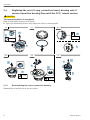
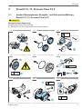
9 Prowirl 72, 73, Prosonic Flow 92 F
9.1 Removing the transmitter, compact and remote version,
Prowirl 72, 73, Prosonic Flow 92 F
LCAUTION
The measuring device is energized!
Risk of fatal injury from electric shock.
‣Open the measuring device only when the device is deenergized.
1 → 2 → 3 →
T20
2.
1.
4 → 5 → 6 →
3 mm 1.
2.
3.
3 (0.12)
1.
2.
4.
7 → 8 → 9 →
T20
1.
2.
4 mm

EA01085D
12 Endress+Hauser
10 → 11
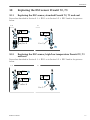
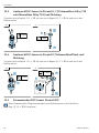
9.2 Replacing the housing seal, cover O-ring, connection board on
Prowirl 72, 73, Prosonic Flow 92 wall holder unit
1 → 2 → 3 →
8 mm
1.
2.
3.
4 → 5 → 6
0.5 ×3.5
1.
2.
T20
1.
2.
9.2.1 Reassembling the wall holder unit
Reassembly is carried out in reverse order.

EA01085D
Endress+Hauser 13
9.3 Replacing the cover O-ring, connection board, removing the sen-
sor connection housing Prowirl 72, 73 remote version
LCAUTION
The measuring device is energized!
Risk of fatal injury from electric shock.
‣Open the measuring device only when the device is deenergized.
1 → 2 → 3 →
0.5 ×3.5
8
7
6
5
4
3
2
1
8
7
6
5
4
3
2
1
1.
2.
4 → 5
T20
4 mm
1.
2.
4 mm
1.
2.
9.3.1 Reassembling the sensor connection housing
Reassembly is carried out in reverse order.

EA01085D
14 Endress+Hauser
9.4 Replacing the cover O-ring, connection board, housing seal of
sensor connection housing Prosonic Flow 92 F, remote version
LCAUTION
The measuring device is energized!
Risk of fatal injury from electric shock.
‣Open the measuring device only when the device is deenergized.
1 → 2 → 3 →
2.
3.
3 mm
1.
0.5 ×3.5
1.
2.
4 → 5 → 6
T20
1.
2.
8 mm
1.
2.
1.
2.
3.
9.4.1 Reassembling the sensor connection housing
Reassembly is carried out in reverse order.

EA01085D
Endress+Hauser 15
10 Replacing the DSC sensor Prowirl 72, 73
10.1 Replacing the DSC sensor, standard Prowirl 72, 73 and seal
Proceed as described in Section 9.1 → 11 or in Section 9.3 → 13 and in the pictures
below.
1 → 2
5 mm
T10
Pos. H
1.
2.
4 mm
Pos. S
1.
2.
10.2 Replacing the DSC sensor, high/low temperature Prowirl 72, 73
and seal
Proceed as described in Section 9.1 → 11 or in Section 9.3 → 13 and in the pictures
below.
1 → 2
5 mm
T10
Pos. H
1.
2.
4 mm
Pos. S
1.
2.

EA01085D
16 Endress+Hauser
10.3 Replacing the DSC sensor, high pressure Prowirl 72, 73 and seal
Proceed as described in Section 9.1 → 11 or in Section 9.3 → 13 and in the pictures
below.
1 → 2
5 mm
T10
Pos. H
1.
2.
4 mm
Pos. S
1. 2.
3.
10.4 Replacing the DSC sensor, maximum pressure Prowirl 72, 73 and
seal
Proceed as described in Section 9.1 → 11 or in Section 9.3 → 13 and in the pictures
below.
1 → 2
6 mm
T10
Pos. H
1.
2.
17 mm
AC
D
B
1.
2.
3.
10.5 Reassembling Prowirl 72, 72
When reassembling, observe the temperature information and torques in the table in →
Section 10.7 → 17!

EA01085D
Endress+Hauser 17
Reassembly is carried out in reverse order. Note the following:
1 → 2
Esc
10.6 Important settings following sensor replacement
After replacing the sensor, the service technician must take the following action: Service
Transducer Block → Sensor Serial Number DSC Sensor. Note: The serial number is
engraved directly onto the DSC sensor. → For more information see the "Serial number of
DSC sensor" section, SH00012.
10.7 Recommended torques for Prowirl 72, 73
Position H = housing support screws
Position S = sensor screws
7****-**0********* 7****-**1*********
7****-**3*********
7****-**4*********
7****-**2********* 7****-**6*********
See
Sect. 10.1
→ 15
Pos. H
See
Sect. 10.1
→ 15
Pos. S
See
Sect. 10.2
→ 15
Pos. H
See
Sect. 10.2
→ 15
Pos. S
See
Sect. 10.3
→ 16
Pos. H
See
Sect. 10.3
→ 16
Pos. S
See
Sect. 10.4
→ 16
Pos. H
See
Sect. 10.4
→ 16
Pos. S
Steps; tighten in
diagonally opposite
sequence
Steps; tighten in
diagonally opposite
sequence
Steps; tighten in
diagonally opposite
sequence
Steps and sequence of tightening
torques
1. 1. 1. 1. 2. 1. 1.
A, B,
A, B,
D, C
2.
B, A,
C, D
3.
A, B,
C, D
Tightening torques
[Nm (lbft)
Tightening torques
[Nm (lbft)
Tightening torques
[Nm (lbft)
Tightening torques [Nm (lbft)
7.0 (5.2) 7.0 (5.2) 7.0 (5.2) 10.0
(7.4)
15.0
(11.0)
14.0
(10.3)
10.0
(7.4)
20.0
(14.8)
26.0
(19.2)
Provide each screw with one drop of lubricant that is suitable for the application temperature
range. The high-temperature paste HTP (50048898) is recommended.

EA01085D
18 Endress+Hauser
11 Prowirl 200
11.1 Removing the Prowirl 200 transmitter, compact version
LCAUTION
The measuring device is energized!
Risk of fatal injury from electric shock.
‣Open the measuring device only when the device is deenergized.
Keep the S-DAT (see Figures 8 + 9 below) in a safe place and insert into the new
transmitter that replaces the old transmitter (→ Section 12.10, → 25, Figure 5 + 6)!
1 → 2 →
3 mm
1.
2.
3 mm (0.12 in)
213 4
3 → 4 → 5 →
3 mm
2.
1.
–+E
Esc

EA01085D
Endress+Hauser 19
6 → 7 → 8 →
9 → 10 → 11 →
1.
2.
T10
8 mm
12 → 13 → 14
~15°

EA01085D
20 Endress+Hauser
11.2 Removing the sensor connection housing Prowirl 200 remote
version
LCAUTION
The measuring device is energized!
Risk of fatal injury from electric shock.
‣Open the measuring device only when the device is deenergized.
1 → 2 →
3 mm
1.
2.
3.
0.5 × 3.5
213 4
1.
2.
3 → 4 → 5 →
T10
6 → 7
1. 2.
T10
Seite wird geladen ...
Seite wird geladen ...
Seite wird geladen ...
Seite wird geladen ...
Seite wird geladen ...
Seite wird geladen ...
Seite wird geladen ...
Seite wird geladen ...
Seite wird geladen ...
Seite wird geladen ...
Seite wird geladen ...
Seite wird geladen ...
Seite wird geladen ...
Seite wird geladen ...
Seite wird geladen ...
Seite wird geladen ...
Seite wird geladen ...
Seite wird geladen ...
Seite wird geladen ...
Seite wird geladen ...
Seite wird geladen ...
Seite wird geladen ...
Seite wird geladen ...
Seite wird geladen ...
Seite wird geladen ...
Seite wird geladen ...
Seite wird geladen ...
Seite wird geladen ...
Seite wird geladen ...
Seite wird geladen ...
Seite wird geladen ...
Seite wird geladen ...
Seite wird geladen ...
Seite wird geladen ...
Seite wird geladen ...
Seite wird geladen ...
-
 1
1
-
 2
2
-
 3
3
-
 4
4
-
 5
5
-
 6
6
-
 7
7
-
 8
8
-
 9
9
-
 10
10
-
 11
11
-
 12
12
-
 13
13
-
 14
14
-
 15
15
-
 16
16
-
 17
17
-
 18
18
-
 19
19
-
 20
20
-
 21
21
-
 22
22
-
 23
23
-
 24
24
-
 25
25
-
 26
26
-
 27
27
-
 28
28
-
 29
29
-
 30
30
-
 31
31
-
 32
32
-
 33
33
-
 34
34
-
 35
35
-
 36
36
-
 37
37
-
 38
38
-
 39
39
-
 40
40
-
 41
41
-
 42
42
-
 43
43
-
 44
44
-
 45
45
-
 46
46
-
 47
47
-
 48
48
-
 49
49
-
 50
50
-
 51
51
-
 52
52
-
 53
53
-
 54
54
-
 55
55
-
 56
56


in anderen Sprachen
- English: Endres+Hauser EA
Verwandte Artikel
-
Endres+Hauser EA Replacing the DSC-Sensor, S-DAT and gasket Mounting Instruction
-
-
-
-
-
Endres+Hauser EA Replacement of parts for the sensor connection housing, remote version Mounting Instruction
-
-
-
Endres+Hauser EA Replacing cover, O-ring cover, Interface gasket Mounting Instruction
-