
Products Solutions Services
Installation Instructions
Replacing the I/O-Module
Proline 200
EA01092D/06/A2/03.23-00
71592431
2023-07-01


EA01092D
Endress+Hauser 3
Replacement of the I/O module
Proline 200
Table of contents
1 Overview of spare part sets ........................................................ 4
2 Intended use ...................................................................... 4
3 Personnel authorized to carry out repairs ........................................... 5
4 Safety instructions ................................................................ 5
5 Symbols used ..................................................................... 6
6 Tool list .......................................................................... 7
7 Replacement of the I/O module .................................................... 8
8 Disposal ......................................................................... 10

EA01092D
4 Endress+Hauser
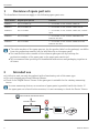
1 Overview of spare part sets
The Installation Instructions apply to the following spare parts sets:
Order number Original spare part set Contents
XPD0015– Set, I/O module, Ex 1 × I/O module, 2-wire, 4-20mA, HART, Ex
XPD0016– Set, I/O module, Ex 1 × I/O module, 2-wire, 4-20mA, HART, PFS, Ex
XPD0018– Set, I/O module 1 × I/O module, 2-wire, 4-20mA, HART, PFS, 4-20mA
input
XPD0093– Set, I/O module 1 × I/O module, 2-wire, 4-20mA, PROFINET with
Ethernet-APL/SPE
XPD0094– Set, I/O module 1 × I/O module, 2-wire, 4-20mA, ModbusTCP with
Ethernet-APL/SPE
• The order number of the spare part set (on the product label on the package) can differ
from the production number (on the label directly on the spare part)!
• You can find the order number of the relevant spare part set by entering the
production number of the spare part in the spare part search tool.
• We recommend that you keep the Installation Instructions and packaging together at
all times.
2 Intended use
• A defective unit can only be replaced with a functioning unit of the same type.
• Use only original parts from Endress+Hauser.
• Check in the W@M Device Viewer if the spare part is suitable for the existing measuring
device.
In some measuring devices, an overview of spare parts is provided inside the device. If
the spare part set is listed in the overview, it is not necessary to check the Device Viewer.
=
www.endress.com/deviceviewer
Order code Description
Ser. No.: 12345...
=

EA01092D
Endress+Hauser 5
3 Personnel authorized to carry out repairs
Authorization to carry out repairs depends on the measuring device's approval type. The table
below shows the authorized group of people in each case.
Whoever carries out the repairs has full responsibility to ensure that work is carried out
safely and to the required quality standard. He/she must also guarantee the safety of the
device following repair.
Measuring device approval Personnel authorized to carry out repairs 1)
Without approval 1, 2, 3
With approval (e.g. IECEx) 1, 2, 3
For custody transfer 4
1) 1 = Qualified specialist on customer side, 2 = Service technician authorized by Endress+Hauser,
3 = Endress+Hauser (return measuring device to manufacturer)
4 = Check with local approval center if installation/conversion must be performed under supervision.
4 Safety instructions
• Check whether the spare part matches the identification labeling on the measuring device,
as described on the cover page.
• The spare part set and the Installation Instructions are used to replace a defective unit with
a functioning unit of the same type.
Only use original parts from Endress+Hauser.
• Comply with national regulations regarding mounting, electrical installation,
commissioning, maintenance and repair.
• The following requirements must be met with regard to specialized technical staff for the
mounting, electrical installation, commissioning, maintenance and repair of the measuring
devices:
• Specialized technical staff must be trained in instrument safety.
• They must be familiar with the individual operating conditions of the devices.
• In the case of Ex-certified measuring devices, they must also be trained in explosion
protection.
• The measuring device is energized! Risk of fatal injury from electric shock. Open the
measuring device only when the device is de-energized.
• For measuring devices intended for use in hazardous locations, please observe the
guidelines in the Ex documentation (XA).
• For measuring devices in safety-related applications in accordance with IEC 61508 or
IEC 61511: following repair, re-commission the device in accordance with the Operating
Instructions. Document the repair.
• Before removing the device: set the process to a safe state and purge the pipe of dangerous
process substances.
• Danger of burns due to heated surfaces! Before commencing work: allow the system and
measuring device to cool down to a touchable temperature.

EA01092D
6 Endress+Hauser
• In the case of devices in custody transfer, the custody transfer status no longer applies once
the seal has been removed.
• The Operating Instructions for the device must be followed.
• Risk of damaging the electronic components! Ensure you have a working environment
protected from electrostatic discharge.
• After removing the electronics compartment cover: risk of electrical shock due to missing
touch protection!
Turn the measuring device off before removing internal covers.
• Modifications to the measuring device are not permitted.
• Only open the housing for a brief period. Avoid foreign objects, moisture or dirt entering the
housing.
• Replace defective seals only with original seals from Endress+Hauser.
• If threads are defective the measuring device must be repaired.
• Threads (e.g. of the electronics compartment cover and connection compartment cover)
must be lubricated if an abrasion-proof dry lubricant is not available. Use acid-free, non-
hardening lubricant.
• If, during repair work, spacing is reduced or the dielectric strength of the measuring device
cannot be guaranteed, perform a test on completion of the work (e.g. high-voltage test in
accordance with the manufacturer's instructions).
• Service plug:
• Do not connect in potentially explosive atmospheres.
• Only connect to Endress+Hauser service devices.
• Observe the instructions for transporting and returning the device outlined in the Operating
Instructions.
Contact Endress+Hauser Service if you have questions: www.addresses.endress.com
5 Symbols used
5.1 Safety symbols
DANGER
This symbol alerts you to a dangerous situation. Failure to avoid this situation will result in
serious or fatal injury.
WARNING
This symbol alerts you to a dangerous situation. Failure to avoid this situation can result in
serious or fatal injury.
CAUTION
This symbol alerts you to a dangerous situation. Failure to avoid this situation can result in
minor or medium injury.
NOTICE
This symbol contains information on procedures and other facts which do not result in
personal injury.

EA01092D
Endress+Hauser 7
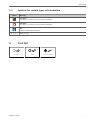
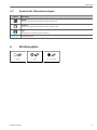
5.2 Symbols for certain types of information
Symbol Meaning
Permitted
Procedures, processes or actions that are permitted.
Forbidden
Procedures, processes or actions that are forbidden.
Tip
Indicates additional information.
1.
,
2.
,
3.
… Series of steps
6 Tool list
3 mm T10 0.5 × 3.5 mm

EA01092D
8 Endress+Hauser
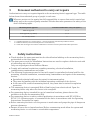
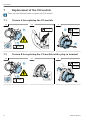
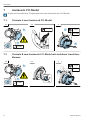
7 Replacement of the I/O module
There are two different ways to replace the I/O module.
7.1 Version A for replacing the I/O module
1 → 2 → 3
3 mm
1.
2.
0.5 × 3.5
T10
0.5 Nm
1.
2.
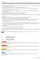
7.2 Version B for replacing the I/O module with a plug-in terminal
1 → 2 → 3
3 mm
1.
2.
T10
0.5 Nm

EA01092D
Endress+Hauser 9
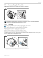
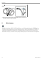
7.3 Reassembling the I/O module
Reassembly is carried out in reverse order. Note the following:
1
For detailed information on the electrical connection, see the "Electrical connection"
section of the Operating Instructions for the device.
7.3.1 Final tasks
Changing the MAC address after replacing the I/O module
Valid for spare part I/O module XPD0093-, XPD0094-
• Corresponds to "Output; input " product: option S, T
• PROFINET with Ethernet-APL/SPE, 10Mbit/s, 2-wire
• Modbus TCP with Ethernet-APL/SPE, 10Mbit/s, 2-wire
The label with the new MAC address must be attached to the transmitter at the correct point.
See the signage plan in the graphics below.
1 →
‣Aluminum transmitter housing Prowirl 200: Attachment of the label
with the new MAC address to the transmitter.

EA01092D
10 Endress+Hauser
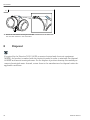
2
‣Stainless transmitter housing Prowirl 200: Attachment of the label with
the new MAC address to the transmitter.
8 Disposal
If required by the Directive 2012/19/EU on waste electrical and electronic equipment
(WEEE), the product is marked with the depicted symbol in order to minimize the disposal
of WEEE as unsorted municipal waste. Do not dispose of products bearing this marking as
unsorted municipal waste. Instead, return them to the manufacturer for disposal under the
applicable conditions.

EA01092D
Endress+Hauser 11
Austausch I/O-Modul
Proline 200
Inhaltsverzeichnis
1 Übersicht Ersatzteilsets .......................................................... 12
2 Bestimmungsgemäße Verwendung ............................................... 12
3 Reparaturberechtigte Personen ................................................... 13
4 Sicherheitshinweise .............................................................. 13
5 Verwendete Symbole ............................................................. 14
6 Werkzeugliste ................................................................... 15
7 Austausch I/O-Modul ............................................................ 16
8 Entsorgung ...................................................................... 18

EA01092D
12 Endress+Hauser
1 Übersicht Ersatzteilsets
Die Einbauanleitung ist für folgende Ersatzteilsets gültig:
Bestellnummer Original Ersatzteilset Inhalt
XPD0015– Set I/O-Modul, Ex 1 × I/O-Modul, 2-Draht, 4-20mA, HART, Ex
XPD0016– Set I/O-Modul, Ex 1 × I/O-Modul, 2-Draht, 4-20mA, HART, PFS, Ex
XPD0018– Set I/O-Modul 1 × I/O-Modul, 2-Draht, 4-20mA, HART, PFS, 4-20mA
Eingang
XPD0093– Set I/O-Modul 1 × I/O-Modul, 2-Draht, 4-20mA, Profinet mit
Ethernet-APL/SPE
XPD0094– Set I/O-Modul 1 × I/O-Modul, 2-Draht, 4-20mA, ModbusTCP mit
Ethernet-APL/SPE
• Die Bestellnummer des Ersatzteilsets (auf dem Produktaufkleber der Verpackung)
kann sich von der Produktionsnummer (auf dem Aufkleber direkt auf dem Ersatzteil)
unterscheiden!
• Durch Eingabe der Produktionsnummer des Ersatzteiles im Ersatzteilfindetool kann
die Bestellnummer des entsprechenden Ersatzteilsets ermittelt werden.
• Wir empfehlen Einbauanleitung und Verpackung immer zusammen aufzubewahren.
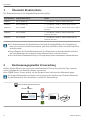
2 Bestimmungsgemäße Verwendung
• Eine defekte Einheit nur gegen eine funktionierende Einheit des gleichen Typs ersetzen.
• Nur Originalteile von Endress+Hauser verwenden.
• Im W@M Device Viewer prüfen, ob das Ersatzteil zum vorliegenden Messgerät passt.
Bei einigen Messgeräten befindet sich im Inneren des Gerätes eine Ersatzteilübersicht.
Ist das Ersatzteilset dort aufgelistet, entfällt die Überprüfung.
=
www.endress.com/deviceviewer
Order code Description
Ser. No.: 12345...
=

EA01092D
Endress+Hauser 13
3 Reparaturberechtigte Personen
Die Berechtigung zur Durchführung einer Reparatur ist von der Zulassung des Messgeräts
abhängig. Die Tabelle zeigt den jeweils berechtigten Personenkreis.
Die Person, die eine Reparatur vornimmt, übernimmt die Verantwortung für die
Sicherheit während der Arbeiten, die Qualität der Ausführung und die Sicherheit des
Geräts nach der Reparatur.
Zulassung des Messgeräts Reparaturberechtigter Personenkreis 1)
ohne Zulassung 1, 2, 3
mit Zulassung (z.B. IECEx) 1, 2, 3
Bei eichfähigem Verkehr 4
1) 1 = Ausgebildete Fachkraft des Kunden, 2 = Von Endress+Hauser autorisierter Servicetechniker,
3 = Endress+Hauser (Messgerät an Hersteller zurücksenden)
4 = Mit der lokalen Zulassungsstelle prüfen, ob ein Ein-/Umbau unter Aufsicht erfolgen muss.
4 Sicherheitshinweise
• Prüfen, ob das vorliegende Ersatzteil zur Kennzeichnung auf dem Messgerät passt, wie auf
der Titelseite beschrieben.
• Ersatzteilset und Einbauanleitung dienen dazu, eine defekte Einheit gegen eine
funktionierende Einheit des gleichen Typs zu ersetzen.
Nur Originalteile von Endress+Hauser verwenden.
• Nationale Vorschriften bezüglich der Montage, elektrischen Installation, Inbetriebnahme,
Wartung und Reparatur einhalten.
• Folgende Anforderungen an das Fachpersonal für Montage, elektrische Installation,
Inbetriebnahme, Wartung und Reparatur der Messgeräte müssen erfüllt sein:
• In Gerätesicherheit ausgebildet.
• Mit den jeweiligen Einsatzbedingungen der Geräte vertraut.
• Bei Ex-zertifizierten Messgeräten: zusätzlich im Explosionsschutz ausgebildet.
• Messgerät unter Spannung! Lebensgefahr durch Stromschlag. Messgerät nur im
spannungslosen Zustand öffnen.
• Bei Messgeräten für den explosionsgefährdeten Bereich: Hinweise in der Ex-
Dokumentation (XA) beachten.
• Bei Messgeräten in sicherheitstechnischen Applikationen gemäß IEC 61508 bzw.
IEC 61511: Nach Reparatur Neuinbetriebnahme gemäß Betriebsanleitung durchführen.
Reparatur dokumentieren.
• Vor einem Geräteausbau: Prozess in sicheren Zustand bringen und Leitung von gefährlichen
Prozessstoffen befreien.
• Verbrennungsgefahr durch heiße Oberflächen! Vor Arbeitsbeginn: Anlage und Messgerät
auf berührungssichere Temperatur abkühlen.
• Bei Messgeräten im abrechnungspflichtigen Verkehr: Nach Entfernen der Plombe ist der
geeichte Zustand aufgehoben.
• Die Betriebsanleitung zum Messgerät ist zu beachten.

EA01092D
14 Endress+Hauser
• Beschädigungsgefahr elektronischer Bauteile! Eine ESD-geschützte Arbeitsumgebung
herstellen.
• Nach Entfernen der Elektronikabdeckung: Stromschlaggefahr durch aufgehobenen
Berührungsschutz!
Messgerät ausschalten, bevor interne Abdeckungen entfernt werden.
• Änderungen am Messgerät sind nicht zulässig.
• Gehäuse nur kurzzeitig öffnen. Eindringen von Fremdkörpern, Feuchtigkeit oder
Verunreinigung vermeiden.
• Defekte Dichtungen nur durch Original-Dichtungen von Endress+Hauser ersetzen.
• Defekte Gewinde erfordern eine Instandsetzung des Messgeräts.
• Gewinde (z.B. von Elektronikraum- und Anschlussraumdeckel) müssen geschmiert sein,
sofern keine abriebfeste Trockenschmierung vorhanden ist. Säurefreies, nicht härtendes
Fett verwenden.
• Wenn bei den Reparaturarbeiten Abstände reduziert oder die Spannungsfestigkeit des
Messgeräts nicht sichergestellt werden kann: Prüfung nach Abschluss der Arbeiten
durchführen (z.B. Hochspannungstest gemäß Herstellerangaben).
• Servicestecker:
• Nicht in explosionsfähiger Atmosphäre anschließen.
• Nur an Servicegeräte von Endress+Hauser anschließen.
• Die in der Betriebsanleitung aufgeführten Hinweise zum Transport und zur Rücksendung
beachten.
Bei Fragen Endress+Hauser Service kontaktieren: www.addresses.endress.com
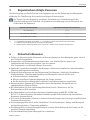
5 Verwendete Symbole
5.1 Warnhinweissymbole
GEFAHR
Dieser Hinweis macht auf eine gefährliche Situation aufmerksam, die, wenn sie nicht
vermieden wird, zu Tod oder schwerer Körperverletzung führen wird.
WARNUNG
Dieser Hinweis macht auf eine gefährliche Situation aufmerksam, die, wenn sie nicht
vermieden wird, zu Tod oder schwerer Körperverletzung führen kann.
VORSICHT
Dieser Hinweis macht auf eine gefährliche Situation aufmerksam, die, wenn sie nicht
vermieden wird, zu leichter oder mittelschwerer Körperverletzung führen kann.
HINWEIS
Dieser Hinweis enthält Informationen zu Vorgehensweisen und weiterführenden
Sachverhalten, die keine Körperverletzung nach sich ziehen.

EA01092D
Endress+Hauser 15
5.2 Symbole für Informationstypen
Symbol Bedeutung
Erlaubt
Abläufe, Prozesse oder Handlungen, die erlaubt sind.
Verboten
Abläufe, Prozesse oder Handlungen, die verboten sind.
Tipp
Kennzeichnet zusätzliche Informationen.
1.
,
2.
,
3.
… Handlungsschritte
6 Werkzeugliste
3 mm T10 0,5 × 3,5 mm

EA01092D
16 Endress+Hauser
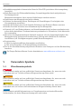
7 Austausch I/O-Modul
Es gibt zwei verschiedene Vorgehensweisen zum Austausch des I/O-Moduls.
7.1 Variante A zum Austausch I/O-Modul
1 → 2 → 3
3 mm
1.
2.
0.5 × 3.5
T10
0.5 Nm
1.
2.
7.2 Variante B zum Austausch I/O-Modul mit steckbarer Anschluss-
klemme
1 → 2 → 3
3 mm
1.
2.
T10
0.5 Nm

EA01092D
Endress+Hauser 17
7.3 Zusammenbau I/O-Modul
Der Zusammenbau erfolgt in umgekehrter Reihenfolge. Folgendes ist zu beachten:
1
Detaillierte Angaben zum elektrischen Anschluss: Kapitel "Elektrischer Anschluss",
Betriebsanleitung zum Gerät.
7.3.1 Abschließende Arbeiten
Änderung der MAC-Adresse nach Austausch I/O- Modul
Gültig für Ersatzteil I/O-Modul XPD0093-, XPD0094-
• Entspricht "Ausgang; Eingang " Produkt: Option S, T
• PROFINET mit Ethernet-APL/SPE, 10Mbit/s, 2-Leiter
• Modbus TCP mit Ethernet-APL/SPE, 10Mbit/s, 2-Leiter
Das Schild mit der neuen MAC-Adresse ist an entsprechender Stelle am Messumformer
anzubringen. Siehe Beschilderungsplan in den Grafiken unten.
1 →
‣Messumformergehäuse Alu Prowirl 200: Anbringen Aufkleber mit neuer
MAC-Adresse auf dem Transmitter.

EA01092D
18 Endress+Hauser
2
‣Messumformergehäuse Rostfrei Prowirl 200: Anbringen Aufkleber mit
neuer MAC-Adresse auf dem Transmitter.
8 Entsorgung
Gemäß der Richtlinie 2012/19/EU über Elektro- und Elektronik-Altgeräte (WEEE) ist das
Produkt mit dem abgebildeten Symbol gekennzeichnet, um die Entsorgung von WEEE als
unsortierten Hausmüll zu minimieren. Gekennzeichnete Produkte nicht als unsortierter
Hausmüll entsorgen, sondern zu den gültigen Bedingungen an den Hersteller zurückgeben.


www.addresses.endress.com
*71592431*
71592431
-
 1
1
-
 2
2
-
 3
3
-
 4
4
-
 5
5
-
 6
6
-
 7
7
-
 8
8
-
 9
9
-
 10
10
-
 11
11
-
 12
12
-
 13
13
-
 14
14
-
 15
15
-
 16
16
-
 17
17
-
 18
18
-
 19
19
-
 20
20


Endres+Hauser EA Replacing the I/O-Module Mounting Instruction
- Typ
- Mounting Instruction
- Dieses Handbuch eignet sich auch für
Verwandte Artikel
-
Endres+Hauser Sealing Ring Mounting Instruction
-
-
-
-
-
Endres+Hauser EA Replacement of parts for the sensor connection housing, remote version Mounting Instruction
-
-
Endres+Hauser EA Dummy plug M20×1.5 Dummy plug NPT½ Mounting Instruction
-
Endres+Hauser KA RIA16 Short Instruction
-