Viessmann 4160 Bedienungsanleitung
- Kategorie
- Kaffeezubehör
- Typ
- Bedienungsanleitung

Bedienungsanleitung
Operation Manual
Innovation,
die bewegt!
Rohrausleger
über 2 bzw. 3 Gleise
Suspended box girder
covering 2 or 3 tracks
1. Wichtige Hinweise / Important information ................................................ 2
2. Einleitung / Introduction ............................................................................. 2
3. Einbau / Mounting ...................................................................................... 2
8. Einstellung / Adjustment ............................................................................ 3

2
DE EN
1. Wichtige Hinweise
Bitte lesen Sie vor der ersten Anwendung des Produktes
bzw. dessen Einbau diese Bedienungsanleitung auf-
merksam durch. Bewahren Sie diese auf, sie ist Teil des
Produktes.
1.1 Sicherheitshinweise
Vorsicht:
Verletzungsgefahr!
Aufgrund der detaillierten Abbildung des Originals bzw.
der vorgesehenen Verwendung kann das Produkt Spit-
zen, Kanten und abbruchgefährdete Teile aufweisen. Für
die Montage sind Werkzeuge nötig.
1.2 Das Produkt richtig verwenden
Dieses Produkt ist bestimmt:
- Zum Einbau in Modelleisenbahnanlagen und Dioramen.
- Zur Verwendung in trockenen Räumen.
Jeder darüber hinausgehende Gebrauch gilt als nicht
bestimmungsgemäß. Für daraus resultierende Schäden
haftet der Hersteller nicht.
1.3 Packungsinhalt überprüfen
Kontrollieren Sie den Lieferumfang auf Vollständigkeit:
- Rohrausleger über 2 bzw. 3 Gleise
- 1 Schraube (2 Schrauben bei Rohrausleger über
3 Gleise)
- Grundträger mit einer Befestigungsbohrung (2 Befes-
tigungsbohrungen bei Rohrausleger über 3 Gleise)
- Anleitung
2. Einleitung
Die fertig montierten und lackierten Rohrausleger zeichnen
sich besonders durch ihre universellen Einsatzmöglich-
keiten aus. Durch die elektrische Trennung der Ausleger
können zwei bzw. drei Gleise unabhängig voneinander
betrieben werden.
3. Einbau
Die Turmmasten der Rohrausleger sind über eine T-Nuten-
Führung mit dem Grundträger verbunden. Dadurch wird
eine Montage von der Oberseite der Anlage aus ermöglicht.
1. Important information
Please read this manual completely and attentively before
using the product for the rst time. Keep this manual. It is
part of the product.
1.1 Safety instructions
Caution:
Risk of injury!
Due to the detailed reproduction of the original and the
intended use, this product can have peaks, edges and
breakable parts. Tools are required for installation.
1.2 Using the product for its correct purpose
This product is intended:
- For installation in model train layouts and dioramas.
- For using in dry rooms only.
Using the product for any other purpose is not approved
and is considered inappropriate. The manufacturer is not
responsible for any damage resulting from the improper
use of this product.
1.3 Checking the package contents
Check the contents of the package for completeness:
- Suspended box girder covering 2 or 3 tracks
- 1 screw (2 screws for suspended box girders covering
3 tracks)
- Ground socket with one mounting hole (2 mounting
holes for suspended box girders covering 3 tracks)
- Manual
2. Introduction
The pre-assembled and coated box girders stand out for
their universal use. Due to their electrical separation two
resp. three tracks can be operated independently.
3. Mounting
The tower masts of the suspended box girders are con-
nected to the ground socket by a t-groove. This allows
mounting from the top of the layout.
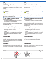
Fig. 1
Abb. 1
Falsch! Richtig!
Wrong! Right!
Falsch! Richtig!
Wrong! Right!

3
Befestigungs-
bohrungen
Mounting holes
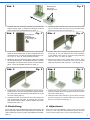
1. Schieben Sie den Turmmast vorsichtig von dem Grund-
träger herunter (Abb. 2). Fassen Sie ihn dazu nicht am
Mast, sondern am Kunststosockel an (Abb. 1).
2. Positionieren Sie den Grundträger an der gewünschten
Stelle auf Ihrer Anlage (Abb. 3). Der richtige Abstand zur
Gleismitte kann mit Hilfe der Mastpositionslehre (Art.
H0: 4197, TT: 4297, N: 4397) bestimmt werden.
3. Markieren Sie mit Hilfe eines Stiftes oder einer Spitze
die Schraubenposition. Anschließend entfernen Sie den
Grundträger und stechen bzw. bohren mit einem Bohrer
(Ø ca. 1 mm) die ermittelte Position vor (Abb. 4).
4. Positionieren Sie nun den Grundträger erneut und be-
festigen diesen mit den beiliegenden Senkkopfschrau-
ben und einem Kreuzschlitzschraubendreher Art. 4199
auf Ihrer Anlage (Abb. 5).
5. Schieben Sie den Turmmast mit der T-Nut wieder auf
den Grundträger auf (Abb. 6). Fassen Sie ihn bitte
auch hierbei nicht am Mast, sondern lediglich am Kunst-
stosockel an (Abb. 1).
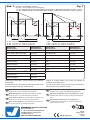
4. Einstellung
Durch die freie Verschiebbarkeit jedes Hängejochs auf
dem Hauptträger lässt sich der Rohrausleger universell für
jedes Gleissystem bzw. für jeden Gleisabstand einstellen
(Abb. 7).
1. Carefully push the tower mast from the ground socket
(g. 2). Please seize the mast only by its plastic base
and do not touch the mast itself (g. 1).
2. Position the ground socket to the desired spot on your
layout (g. 3). You can determine the correct distance
to the middle of the track by using the mast positioner
(item H0: 4197, TT: 4297, N: 4397).
3. Mark the position of the screw with a pencil. Then
remove the ground socket and prick or pre-drill the
determined position with a drill (ca. 1 mm Ø) (g. 4).
4. Position the ground socket on your model train layout
again and fasten with the enclosed screws and a screw-
driver item 4199 (g. 5).
5. Slide the tower mast with the t-groove back onto the
ground socket (g. 6). Please seize only by the plastic
base, not by the mast itself (g. 1).
4. Adjustment
Due to the free relocatability of each yoke on the main
socket you can adjust the suspended box girder universal
for each track system resp. every track distance (g. 7).
Fig. 2
Abb. 2
Befestigungs-
bohrung
Mounting hole
Abb. 3 Fig. 3 Abb. 4 Fig. 4
Abb. 5 Fig. 5 Abb. 6 Fig. 6

4
Änderungen vorbehalten. Keine Haftung für Druckfehler
und Irrtümer.
Die aktuelle Version der Anleitung nden Sie auf der Viess-
mann Homepage unter der Artikelnummer.
Subject to change without prior notice. No liability for
mistakes and printing errors.
You will nd the latest version of the manual on the Viess-
mann website using the item number.
Modellbauartikel, kein Spielzeug! Nicht geeignet für
Kinder unter 14 Jahren! Anleitung aufbewahren!
Model building item, not a toy! Not suitable for children
under the age of 14 years! Keep these instructions!
Ce n’est pas un jouet! Ne convient pas aux enfants de moi-
ns de 14 ans! Conservez cette notice d’instructions!
Não é um brinquedo! Não aconselhável para menores de
14 anos! Conservar o manual de instruções!
Modelbouwartikel, geen speelgoed! Niet geschikt voor
kinderen onder 14 jaar! Gebruiksaanwijzing bewaren!
Articolo di modellismo, non è un giocattolo! Non adatto
a bambini al di sotto dei 14 anni! Conservare istruzioni per
l’uso!
Artículo para modelismo ¡No es un juguete! No
recomendado para menores de 14 años! Conserva las
instrucciones de servicio!
DE
EN
FR
NL
IT
ES
PT
Made in Europe
Viessmann
Modelltec
hnik GmbH
Bahnhofstraße 2a
D - 35116 Hatzfeld-Reddighausen
+49 6452 9340-0
www.viessmann-modell.de
98794
Stand 05/sw
01/2024
Ho/Kf
Fig. 7
Abb. 7
Gleissystem
Track system
Gleisabstand c
Track distance c
H0
Roco LINE + Roco geoLINE 61,6 mm
Fleischmann Modell-Gleis 58,0 mm
Fleischmann Pro-Gleis 63,5 mm
Märklin K-Gleis 64,6 mm
Märklin M-Gleis 77,4 mm
Märklin C-Gleis 77,5 mm
Tillig H0-Elite 59,0 mm
TT
Tillig-Standard 44,0 mm
Tillig-Modellgleis 43,0 mm
Gleissystem
Track system
Gleisabstand c
Track distance c
N
Hornby/Arnold 30,0 mm
Fleischmann Bettungsgleis 33,6 mm
Fleischmann-Gleis ohne Bettung 33,6 mm
Kato 33,0 mm
Roco 33,6 mm
Minitrix 33,6 mm
Peco 26,5 mm
aa
b bc c c
dd
a: H0: 15,09 cm, TT: 10,90 cm, N: 8,2 cm
b: H0: 3,75 cm, TT: 2,75 cm, N: 2,0 cm
d: H0: 11,75 cm, TT: 7,80 cm, N: 6,0 cm
a: H0: 17,00 cm, TT: 12,40 cm, N: 9,25 cm
b: H0: 3,75 cm, TT: 2,75 cm, N: 2,00 cm
d: H0: 19,50 cm, TT: 11,80 cm, N: 9,45 cm
b b
Ausleger, 5 Stück/Beam, 5 pieces
H0: 4171, 41711 kurz/short, 41712 lang/long
TT: 4271 mit/with 4284 TT Universal-Halterung für Ausleger, 5 Stück/Universal holder for beam, 5 pieces
N: 4371 mit/with 4384 N Universal-Halterung für Ausleger, 5 Stück/Universal holder for beam, 5 pieces
e
e
e:
FR
-
 1
1
-
 2
2
-
 3
3
-
 4
4


Viessmann 4160 Bedienungsanleitung
- Kategorie
- Kaffeezubehör
- Typ
- Bedienungsanleitung
in anderen Sprachen
- English: Viessmann 4160 Owner's manual