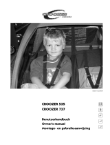
Croozer Dog 2008-2013 Bedienungsanleitung
- Typ
- Bedienungsanleitung

CROOZER DOG
Benutzerhandbuch
Owner’s manual
Gebruikershandleiding
Stand 01/2005

Inhaltsverzeichnis
Benutzerhandbuch
1. Montage ............................................................................................................................................................................................................ 3
1.1. Lieferzustand .................................................................................................................................................................................................... 3
1.2. Montage der Achsen in den Laufrädern ................................................................................................................................................. 3
1.3. Demontage und Montage der Laufräder.................................................................................................................................................. 4
2. Funktionen ........................................................................................................................................................................................................ 4
2.1 Auffalten, Verriegeln und Zusammenfalten des Aufbaus.................................................................................................................... 4
2.2 Klappfunktion der Deichsel.......................................................................................................................................................................... 5
2.3 Wimpel................................................................................................................................................................................................................. 6
3. Inbetriebnahme ............................................................................................................................................................................................... 6
3.1 Befestigung der Deichsel am Fahrrad....................................................................................................................................................... 6
3.1.1 Montage des Kupplungsstücks am Fahrrad........................................................................................................................................... 6
3.1.1.1 Fahrrad mit Vollachse..................................................................................................................................................................................... 6
3.1.1.2 Fahrrad mit Schnellspanner......................................................................................................................................................................... 7
3.1.2 Montage der Deichsel am Kupplungsstück............................................................................................................................................ 8
3.1.3 Platzierung des transportierten Gewichtes.............................................................................................................................................. 8
4. Sicherheitshinweise ....................................................................................................................................................................................... 8
5. Wartung, Pflege und Lagerung ................................................................................................................................................................... 9
5.1 Deichsel ............................................................................................................................................................................................................. 9
5.2. Laufräder .......................................................................................................................................................................................................... 9
5.3. Stoffaufbau ........................................................................................................................................................................................................ 9
5.4. Aufbewahrung................................................................................................................................................................................................... 9
5.5. Allgemeine Wartungsarbeiten ..................................................................................................................................................................... 9
6. Gewährleistung/ Garantie ........................................................................................................................................................................... 9
Owner’s manual ........................................................................................................................................................................................................ 11
Gebruikershandleiding ........................................................................................................................................................................................ 20
2
Dieses Benutzerhandbuch ist urheberrechtlich geschützt und Eigentum der PRODEK GmbH, Köln.
Abdruck oder Vervielfältigung, auch auszugsweise, von Text und / oder Bildern in Medien aller Art ist nur zulässig
mit schriftlicher Genehmigung der PRODEK GmbH.

3
Herzlichen Glückwunsch zum Kauf dieses Hundetransport- und
Mehrzweck-Anhängers!
Ihr neuer CROOZER DOG zeichnet sich durch hervorragende
Qualität, Bedienfreundlichkeit und grossen praktischen
Nutzwert, auch als Transportanhänger aus.
Achtung: Produktionsbedingte
Änderungen vorbehalten.
Fragen Sie im Zweifel Ihren Fachhändler!
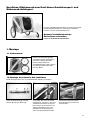
1. Montage
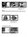
Rahmen mit Stoffaufbau (gefaltet),
2 Laufräder, Deichsel mit Kupplung
(unter den Anhänger geklappt),
kleiner Transportkarton mit
Schraubenschlüssel sowie 2 Achsen
mit Unterlegscheibe, Wellscheibe
und Stop-Mutter
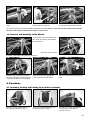
1.1. Lieferzustand
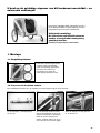
1.2. Montage der Achsen in den Laufrädern
Achse mit Wellscheibe (1), Unterleg-
scheibe (2) und Stop-Mutter (3).
Zur Montage der Achse im Laufrad
empfehlen wir, die Achse in der Achs-
aufnahme des Rahmens zu fixieren.
Dazu stecken Sie die Achse mit auf-
gelegter Wellscheibe in die Achs-
aufnahme, bis die Bohrungen von
Achse und Achsaufnahme fluchten.
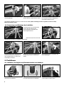
Stecken Sie den Sicherungsstift
durch die Bohrung in Achse und
Achsaufnahme
Dieser Montageschritt ist nur vom erstaufbauenden Händler vorzunehmen.

Zunächst die in Fahrtrichtung rechte
Seitenwand hochklappen
Anschließend auch die in Fahrtrich-
tung linke Seitenwand hochklappen.
4
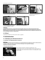
und sichern ihn durch Umklappen des
Sicherungsbügels.
Zur Montage der Achse im Laufrad
stecken Sie das Laufrad auf die Achse,
legen die Unterlegscheibe auf und zie-
hen die Mutter mit dem beiliegenden
Schraubenschlüssel fest an.
Anschließend verbleibt die Achse im Laufrad montiert. Eine spätere Demontage ist nicht vorgesehen, da dann die Stop-
Mutter ihre Funktion verliert.
1.3. Demontage und Montage der Laufräder
Zur Demontage des Laufrades lösen
Sie den Sicherungsbügel des
Sicherungsstiftes und ziehen den
Sicherungsstift heraus.
Ziehen Sie Laufrad mit Achse ab.
Stecken Sie die Achse des Laufrades
in die Achsaufnahme am Rahmen, so
dass die Bohrungen von Achse und
Achsaufnahme fluchten.
Stecken Sie den Sicherungsstift durch
die Bohrung in Achse und Achsauf-
nahme
und sichern ihn durch Umklappen des
Sicherungsbügels.
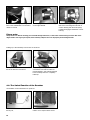
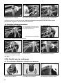
2. Funktionen
2.1. Auffalten, Verriegeln und Zusammenfalten des Aufbaus
Heckfenster und in Fahrtrichtung
rechte Klappe im Dach öffnen.
Montage des Laufrades in umgekehrter Reihenfolge:

Achtung:
Achten Sie immer darauf, daß der Sicherungsstift durch beide Bohrungen, sowohl die im Gegenlager als auch die im Querrohr
gesteckt ist. Ihr Hund könnte verletzt werden, wenn der Aufbau durch nicht korrekt gesichertes Querrohr zusammenfaltet.
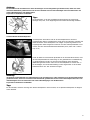
Das an der in Fahrtrichtung linken
Seitenwand drehbar gelagerte obere
Querrohr hochklappen
bis es in seinem Gegenlager an der
rechten Seitenwand einrastet.
Sicherungsstift durch die fluchtenden
Bohrungen im Querrohr und seinem
Gegenlager stecken, bis die kleine
federbelastete Kugel hinter den
Gegenlager einrastet.
5
Zusammenfalten in umgekehrter Reihenfolge.
Immer erst die in Fahrtrichtung linke
Seitenwand herunterklappen.
Beim Herunterklappen der rechten Sei-
tenwand darauf achten, daß Front und
Rückwand nach innen gedrückt werden,
um im zusammengefalteten Zustand
Beschädigungen zu vermeiden.
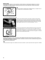
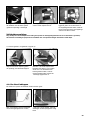
Nach vorn geklappt zum Ankuppeln
ans Fahrrad,
unter das Fahrzeug geklappt zur
Erreichung kleiner Abmessungen
beim Verstauen.
2.2. Klappfunktion der Deichsel
Die Deichsel kann in zwei Positionen befestigt werden:

6
Achtung:
Vergewissern Sie sich immer, dass die Deichsel ordnungsgemäß gesichert ist! Der Sicherungsstift muß durch beide
Bohrungen, sowohl in der Deichselkulisse als auch in der Deichsel gesteckt und der Sicherungsbügel über das Ende des
Sicherungsstiftes geschnappt sein. Eine nicht ordnungsgemäß gesicherte Deichsel kann sich während der Fahrt lösen. Dies
ist extrem gefährlich und kann zu Unfällen führen.
Sicherungsbügel des Sicherungsstiftes
lösen und Sicherungsstift herausziehen,
Deichsel in die andere Position klappen,
Zum Wechseln der Positionen:
und Sicherungsbügel über das Ende
des Sicherungsbügels schnappen.
Endzustand des Sicherungsstiftes
Sicherungsstift durch die fluchtenden
Bohrungen in Deichselkulisse und
Deichsel stecken
2.3. Wimpel
Zur Montage des Wimpels ist hinten links eine Lasche vorgesehen.
3. Inbetriebnahme
3.1. Befestigung der Deichsel am Fahrrad
3.1.1. Montage des Kupplungsstücks am Fahrrad
Achtung:
Im Fahrradanhängerbetrieb hängt Ihre Sicherheit von der korrekten Montage der Kupplung ab. Gehen Sie daher besonders
sorgfältig vor. Fahren Sie niemals mit einer unzureichend befestigten oder ungesicherten Kupplung.
Fragen Sie im Zweifel Ihren Fachhändler!
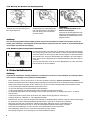
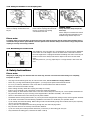
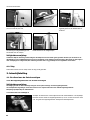
3.1.1.1. Fahrrad mit Vollachse
Linke Achsmutter demontieren. Eventuell vorhandene Fixier- oder
Unterlegscheiben können in der Regel beibehalten werden. Kupplungsstück auf
die Achse setzen und Achsmutter wieder montieren. Das Kupplungsstück waage-
recht ausrichten.

7
Achtung:
Die Achsmutter muß mit mindestens 5 vollen Umdrehungen auf das Achsgewinde geschraubt werden, damit eine ausrei-
chend hohe Klemmkraft gewährleistet ist. Ein zu kurzes Gewinde kann zum unbeabsichtigten Lösen des Hinterrades und
somit zu Beschädigungen und Unfällen führen.
Fragen Sie im Zweifel Ihren Fachhändler!
Tipp:
für die Fahrräder, an die das mitgelieferte Kupplungsstück für waagerechte
Montage nicht passt, ist ein Kupplungsstück für senkrechte Montage erhältlich.
3.1.1.2. Fahrrad mit Schnellspanner
Schnellspanner demontieren und mit der Schnellspannachse durch das
Kupplungsstück führen. Schnellspanner wieder durch die Hohlachse schieben, die
Mutter montieren und Schnellspanner mit richtiger Vorspannung klemmen. Das
Kupplungsstück dabei waagerecht ausrichten und den Schnellspannhebel so aus-
richten, dass der Vierkantdeichselanschluß darüber passt. (siehe auch 1. Bild in
Kap. 3.1.2.)
Damit die Nabe mit ausreichender Spannkraft in der Achsaufnahme klemmt, muss
der Schnellspannhebel auf seinem Weg von der geöffneten bis zur Mittelstellung
zu greifen beginnen und bis zur geschlossenen Stellung gegen spürbaren
Widerstand gedrückt werden. Lässt sich der Schnellspanner zu schwer oder zu
leicht betätigen, wird die Grundeinstellung mit der Gegenmutter an der anderen
Nabenseite durch Auf- bzw. Zudrehen korrigiert.
Achtung:
das Gewinde der Einstellmutter des Schnellspanners muß mit mindestens 5 vollen Umdrehungen auf die Schnellspannachse
geschraubt werden, damit eine ausreichend hohe Klemmkraft gewährleistet ist. Eine zu kurze Schnellspannachse kann zum
unbeabsichtigten Lösen des Hinterrades und somit zu Beschädigungen oder Unfällen führen.
Fragen Sie im Zweifel Ihren Fachhändler!
Tipp:
für die Fahrräder, an denen die Länge des Serienschnellspanners nicht ausreicht, ist ein Spezialschnellspanner mit längerer
Achse erhältlich.

8
Achtung:
eine nicht ordnungsgemäß montierte Kupplung könnte sich lösen und beim Bremsen seitlich in die Speichen geraten. Es
besteht große Verletzungs- und Sturzgefahr für den Fahrradfahrer. Vergewissern Sie sich deshalb vor jedem Fahrtantritt über
den korrekten und festen Sitz der Kupplung.
3.1.3. Platzierung des transportierten Gewichtes
Für das Fahrverhalten eines Fahrrades mit Anhänger spielt die Gewichtsverteilung
der Ladung eine grosse Rolle. Zuviel Gewicht vor den Laufradachsen des Hängers
erhöht die Stützlast an der Kupplung. Das wirkt sich negativ auf das Fahrverhalten
des Fahrrades aus. Achten Sie beim Beladen des Anhängers mit Transportgütern
daher darauf, schwere Gegenstände im Ladenflächenbereich über den Achsen zu
verstauen.
Auch Ihr Hund, besonders wenn er ein hohes Eigengewicht hat, sollte sich besten-
falls im Bereich der Achse aufhalten.
4. Sicherheitshinweise
Achtung:
Vermeiden Sie unbedingt das einseitige Überfahren von Hindernissen, da dieses zu einem Umkippen des Fahrzeuges führen
kann und zwar unabhängig von der gefahrenen Geschwindigkeit.
•
Dieser Anhänger ist nur für den Transport von Hunden und Gütern zugelassen, nicht für den Transport von Kindern!
•
Befördern Sie niemals Ihren Hund und gleichzeitig Transportgüter, Ihr Hund könnte durch verrutschende Ladung verletzt werden.
•
Nehmen Sie keinerlei Änderungen an dem Fahrzeug vor, die nicht in diesem Benutzerhandbuch beschrieben werden.
•
Vor der Benutzung die Bedienungsanleitung aufmerksam lesen.
•
Vor der Fahrt Kupplung und Sicherungsband korrekt befestigen.
•
Auf die richtige Montage aller Bauteile insbesondere der Räder und der Deichsel achten.
•
Vor Fahrtantritt überprüfen, dass der Anhänger nicht mit Teilen des Fahrrades, wie Pedalen, Bremsen u.ä. in Kontakt
kommen kann.
•
Achten Sie besonders darauf, dass das Querrohr des Aufbaus korrekt gesichert ist, siehe Kap. 2.1.
•
Anhänger dürfen nur unbeladen an- oder abgekuppelt werden.
•
Bedenken Sie, dass sich das Fahrverhalten Ihres Fahrrades im Anhängerbetrieb verändert und dass höhere Anforderungen
an die Bremsen und die Rahmenbelastbarkeit gestellt werden. Fragen Sie im Zweifel Ihren Fachhändler.
•
Fahren Sie umsichtig und vermeiden Sie Vollbremsungen. Beim Abbremsen mit der Vorderradbremse im
Anhängerbetrieb ist das Fahrrad und vor allem die Fahrradgabel erheblichen Belastungen ausgesetzt.
•
Ziehen Sie Fahrradanhänger nur, wenn Sie dazu ausreichend Erfahrung und Kraft besitzen.
•
Fahrradanhänger dürfen nicht von motorisierten Zweirädern gezogen werden.
•
Mit Anhänger langsamer und umsichtiger als mit einem Einzelfahrrad fahren.
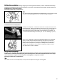
3.1.2. Montage der Deichsel am Kupplungsstück
Schieben Sie den Vierkantdeichsel-
anschluss über das ans Fahrrad mon-
tierte Kupplungsstück.
Stecken Sie den Federclipbolzen durch
die Bohrungen der beiden Kupplungs-
teile und schliessen Sie den Bügel, so
dass die Öffnung des Clips das Bol-
zenende umfasst.
Achtung:
Immer das Sicherungsband an der
Kettenstrebe befestigen!
Legen Sie das Sicherungsband um den
Hinterbau des Fahrradrahmens und be-
festigen Sie den Karabinerhaken am D-
Ring der Deichsel.

9
5. Wartung, Pflege und Lagerung
5.1. Deichsel
Die Deichsel regelmäßig auf Anzeichen von Beschädigung (z.B. Risse) überprüfen. Bei jeder Art von Beschädigung muß die
Deichsel ausgetauscht werden, um Bruch und damit einhergehende Unfallgefahr zu vermeiden.
Fragen Sie im Zweifel Ihren Fachhändler.
•
In Kurven höchstens mit Schrittgeschwindigkeit fahren, Anhänger könnte kippen.
•
Die zugelassene Höchstgeschwindigkeit für das Fahren mit einem Fahrradanhänger beträgt 25 km/h.
•
Maximale Zuladung 45 kg
•
Reifendruck 2,5 bar
•
Bei Dunkelheit müssen Fahrrad und Anhänger mit vorschriftsmäßiger Beleuchtung und Reflektoren ausgestattet sein.
•
Zum Parken des Gespanns auf sicheren Stand achten. Das Ankuppeln des Anhängers verändert den
Schwerpunkt des Fahrrades, wodurch einige Fahrradständer, insbesondere Doppelbeinständer, untauglich werden. Das
Fahrrad kann umfallen, was Schäden am Anhänger, der Deichsel oder der Anhängerkupplung verursachen kann.
•
Anhänger, auch im gefalteten Zustand, dürfen nicht auf dem Fahrzeugdach eines Kraftfahrzeugs transportiert werden.
5.2. Laufräder
Lassen Sie die Laufräder (Bereifung, Felgen, Speichenspannung, Achslagerung) mindestens zweimal jährlich von Ihrem
Fachhändler überprüfen.
Reinigen Sie die Laufräder regelmäßig und behandeln Sie sie, vor allem vor den Wintermonaten, mit Pflegewachs.
5.3. Stoffaufbau
Reinigen Sie Ihren CROOZER DOG mit Wasser und Spülmittel. Keine aggressiven Reinigungsmittel verwenden, da diese
Stoffe und Oberflächen dauerhaft schädigen könnten.
5.4. Aufbewahrung
Bewahren Sie Ihren CROOZER DOG an einem trockenen, gut belüfteten Ort auf. Vor der Lagerung sollte das Fahrzeug trok-
ken sein, um Schimmelbefall und die Bildung von Stockflecken zu vermeiden. Setzen Sie das Fahrzeug so wenig wie möglich
direkter Sonneneinstrahlung aus, um ein Verblassen der Farben zu verhindern. Lagern Sie den Fahrradanhänger nicht über
längere Zeit hinweg am Fahrrad angekuppelt.
5.5. Allgemeine Wartungsarbeiten
Pflegen Sie Ihr Fahrzeug. Alle lackierten, verchromten oder verzinkten Teile (incl. Schraubverbindungen) sollten regelmäßig gerei-
nigt und mit handelsüblichen Pflegemitteln geschützt werden. Fragen Sie Ihren Fachhändler nach geeigneten Pflegemitteln.
6. Gewährleistung/ Garantie
Es gilt die gesetzliche Sachmängelhaftung. Schäden, die durch unsachgemäße Beanspruchung, Gewalteinwirkung, ungenü-
gende Wartung, oder normale Abnutzung entstehen, sind von der Sachmängelhaftung ausgeschlossen.
Die Dauer der gesetzlichen Gewährleistung richtet sich nach den jeweiligen landesspezifischen Bestimmungen.
Unsere Produkte weisen Bauteile oder Komponenten auf, die auch bei üblichem Gebrauch einem natürlichem Verschleiß
unterliegen, der jedoch sehr stark von der individuellen Art und Intensität der Nutzung sowie dem Wartungs- und
Pflegezustand abhängt.
Insbesondere bei intensiver Nutzung (tagtäglicher Gebrauch bei jeder Witterung o.ä.) können einzelne Bauteile oder
Komponenten ihre Verschleißgrenze auch vor Ablauf der gesetzlichen Gewährleistungsfrist erreichen. In diesen Fällen nut-
zungsbedingten vorzeitigen Verschleißes liegt jedoch nicht automatisch ein Mangel des Produktes vor.
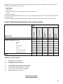
Zu Ihrer Information haben wir deshalb in der folgenden Tabelle die wichtigen Verschleißteile aufgeführt und typische nut-
zungsbedingte Verschleißfaktoren genannt, die das Erreichen der Verschleißgrenze erheblich beeinflussen können.
Unabhängig von der Art und Intensität der Nutzung sowie der Pflege und Wartung tritt bei einem Fahrrad-Anhänger an
Komponenten und Bauteilen ein funktionsbedingter Verschleiß auf.

10
Stand: 01-2005
www.croozer.info
Das Erreichen der Verschleißgrenze hängt stark von der individuellen Art und Intensität der Nutzung sowie der Pflege und
Wartung durch die Nutzer ab, wie :
•
der Laufleistung in km
•
der Belastung durch Beladung
•
dem Fahrstil
•
dem Witterungseinfluss durch: UV-Strahlung, Feuchtigkeit, Schmutz, Temperatur, salzhaltige Luft etc
•
der Lagerung
•
dem Pflegezustand
Bitte beachten Sie die folgende Tabelle (‚Verschleißfaktoren‘). Dieser Tabelle können Sie im Detail entnehmen, welche
Faktoren den Verschleiß der einzelnen Bauteile besonders beeinflussen.
Die Tabelle ist eine Ergänzung der vorliegenden Bedienungsanleitung. Beachten Sie bitte unbedingt die Hinweise zu Wartung,
Pflege und Lagerung.
Bauteile
Verschleißfaktoren
Belastung durch: Ladung xx x xx xx
Witterungseinfluß: UV-Strahlung xx
*1
xx xx
*2
Feuchtigkeit xx
*3
xx x x
Schmutz xx xx x x
Temperatur xx x
salzhaltige Luft x xx xx x xx
Berührung mit Salzwasser xx xx xxx x xx
mit Salz gestreute Straßen xx xx xxx x xx
Lagerung x x x
*4
Verschleißwirkung:
x: Mäßige Auswirkung auf den Verschleiß
xx: Starke Auswirkung auf den Verschleiß
xxx: Erhebliche Auswirkung auf den Verschleiß
*1 - Starke Sonneneinstrahlung möglichst vermeiden!
*2 - Lange Sonneneinstrahlung möglichst vermeiden!
*3 - Durch trockenes Einlagern Schimmelbildung vermeiden!
*4 - Bei hängender Lagerung kein Verschleiß!
*5 - Luftdruck regelmäßig kontrollieren!
Verdeck
Felgen, Naben &
Speichen
Boden, Seitenwände
Einflußfaktoren, die den Verschleiß von Fahrradanhängern erhöhen:
Deichsel,
Kupplung
Reifen
*5

11
Table of contents
1. Assembly .......................................................................................................................................................................................................... 12
1.1. Parts .................................................................................................................................................................................................................... 12
1.2. Assembly of the Axles in the Wheels ....................................................................................................................................................... 12
1.3. Removal and Assembly of the Wheels...................................................................................................................................................... 13
2. Functions .......................................................................................................................................................................................................... 13
2.1 Unfolding, Locking and Folding up the Fabric Assembly................................................................................................................... 13
2.2 The Swivel Function of the Drawbar.......................................................................................................................................................... 14
2.3 Safety Flag......................................................................................................................................................................................................... 15
3. Initial Operation .............................................................................................................................................................................................. 15
3.1 Fixing the Drawbar on the Bicycle............................................................................................................................................................. 15
3.1.1 Fitting the Coupling Unit to the Bicycle ................................................................................................................................................... 15
3.1.1.1 Bicycle with Full Axle...................................................................................................................................................................................... 15
3.1.1.2 Bicycle with Quick Release Axle................................................................................................................................................................ 16
3.1.2 Fitting the Drawbar to the Coupling Unit.................................................................................................................................................. 17
3.1.3 Distributing the Load Carried....................................................................................................................................................................... 17
4. Safety Instructions ......................................................................................................................................................................................... 17
5. Service, Care and Storage .......................................................................................................................................................................... 18
5.1 Hitch Arm .......................................................................................................................................................................................................... 18
5.2. Wheels ............................................................................................................................................................................................................... 18
5.3. Fabric Assembly ............................................................................................................................................................................................ 18
5.4. Storage............................................................................................................................................................................................................... 18
5.5. General Maintenance .................................................................................................................................................................................... 18
6. Warranty............................................................................................................................................................................................................. 18
This Owner’s Manual is protected by copyright and remains the property of PRODEK GmbH, Cologne.
All reproduction and duplication of text and/or illustrations, or any part of these, in whatever media,
is only permitted with the written authorisation of PRODEK GmbH.

12
Congratulations on buying this dog carrier and multipurpose
trailer!
Your new CROOZER DOG stands out because of its excel-
lent quality, user-friendliness, practicality, and high efficiency
as a transport trailer.
Please note: We reserve the right to
make changes relating to production.
If in doubt ask your specialist dealer!
1. Assembly
Frame with fabric assembly (folded),
2 wheels, drawbar with coupling
(swivelled back under the trailer),
small carry-box with spanners, and
2 axles complete with plain washer,
corrugated washer and stop nut
1.1. Parts
1.2. Assembly of the Axles in the Wheels
Axle with corrugated washer (1), plain
washer (2) and stop nut (3).
When assembling the axle in the
wheel, we recommend that you secu-
re the axle in the hollow axle of the
frame. To do this, insert the axle with
its plain washer into the hollow axle
until the holes of the axle and hollow
axle are aligned.
Insert the securing pin through the
holes in the axle and hollow axle
This assembly step may only be carried out by a dealer assembling the trailer for the first time.

13
First open out the sidewall that is on
the right in the direction of travel.
Then open out the sidewall that is on
the left in direction of travel.
and secure it by turning the safety clip
down.
To assemble the axle in the wheel,
insert the wheel on the axle,
put the washer on, and tighten up the
nut fully using the spanner included.
From now on the axle remains permanently assembled to the wheel. There is no provision for later removal of the axle from
the wheel, as the stop nut would not be re-usable in such an event.
1.3. Removal and Assembly of the Wheels
To remove the wheel loosen the safety
clip on the securing pin and withdraw
the securing pin.
Pull off the wheel and axle.
Insert the axle of the wheel in the hol-
low axle on the frame, so that the holes
of the axle and hollow axle are aligned.
Insert the securing pin through the
holes in the axle and hollow axle
and secure it by turning the safety clip
down.
2. Functions
2.1. Unfolding, Locking and Folding up the Fabric Assembly
Open the rear window and the rear
roof flap that is on the right in
direction of travel.
Assembly of the wheel is the reverse of the above:

14
Please note:
Always make sure that the securing pin is inserted through both holes, i.e. that of the counter bearing as well as that of the
diagonal tube. Your dog may be injured, if the assembly collapses due to an improperly secured diagonal tube.
Swivel out the rotating upper diagonal
tube of the sidewall that is on the left in
direction of travel
until it engages in its counter bearing
on the right sidewall.
Insert the securing pin through the alig-
ned holes of the diagonal tube and its
counter bearing until the small spring-
loaded ball engages behind the counter
bearing.
Folding up of the assembly is the reverse of the above.
: Always fold in the sidewall that is on
the left in direction of travel first.
When folding in the right sidewall make
sure that the front and rear walls are
pressed inwards – this prevents damage
to the assembly when it is completely
folded up.
Swivelled forward to couple up with
the bicycle,
and swivelled under the carrier to
make it more compact when stored.
2.2. The Swivel Function of the Drawbar
The drawbar can be attached in two positions:

15
Please note:
Always ensure that the drawbar is properly secured! The securing pin must be inserted through both the holes – i.e. that of
the drawbar yoke as well as that of the drawbar itself – and the safety clip must be snapped over the end of the securing
pin. A drawbar which has not been secured properly can come loose during travel. This is extremely dangerous and can
cause accidents.
Loosen the safety clip on the securing
pin and withdraw the securing pin,
swivel the drawbar into the other
position,
To change the positions:
and snap the safety clip over the end
of the securing pin.
Final securing pin assembly
insert the securing pin through the
aligned holes in the drawbar yoke and
drawbar
2.3. Safety Flag
A flap for fixing the safety flag is provided on the left at the rear end.
3. Initial Operation
3.1. Fixing the Drawbar on the Bicycle
3.1.1. Fitting the Coupling Unit to the Bicycle
Please note:
When pulling the trailer behind a bicycle your own safety depends on the coupling being properly fitted. Proceed therefore
with special care. Never cycle with a coupling that is inadequately attached or not secured.
If in doubt ask your specialist dealer!
3.1.1.1. Bicycle with Full Axle
Remove the left hand axle nut. Any spacers or plain washers can generally be
retained. Put the coupling unit on the axle and reattach the nut. Hold the coupling
unit horizontal throughout.

16
Please note:
The axle nut must be tightened on the axle thread by at least 5 full turns, so that adequate clamping force is ensured.
A thread which is too short can lead to accidental loosening of the rear wheel and thereby to damage and accidents.
If in doubt ask your specialist dealer!
Tip:
For bicycles where the coupling unit for horizontal assembly as supplied does not
fit, a coupling unit for vertical assembly is available.
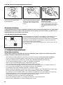
3.1.1.2. Bicycle with Quick Release Axle
Detach the quick release and guide it through the coupling unit along with the
quick release axle. Push the quick release through the hollow axle again, attach
the nut and clamp the quick release with the correct prestress. At the same time
align the coupling unit horizontally, along with the quick release lever, so that the
square drawbar connector fits on top. (see also illustration 1 in 3.1.2.)
In order to ensure that the hub is clamped sufficiently in the hollow axle, the Q.R.
lever must begin gripping as it moves from the open to the middle position, and
approaching the closed position you should clearly feel resistance as you tighten.
If it is too easy or too difficult to move the quick release lever, tighten or loosen the
Q.R. lock nut on the other side of the hub.
Please note:
The thread of the adjusting nut of the quick release must be tightened on the quick release axle by at least 5 full turns, so
that adequate clamping force is ensured. A quick release axle which is too short can lead to accidental loosening of the rear
wheel and thereby to damage or accidents.
If in doubt ask your specialist dealer!
Tip:
For bicycles where the length of the standard quick release is insufficient, a special quick release with longer axle is available.
noticeable
resistance
fix the lever properly

17
Please note:
A coupling, which is incorrectly fitted, could become loose and could slip sideways into the spokes during braking. There is
considerable danger that the cyclist will fall or become injured. Please therefore always ensure before every journey that the
coupling is correctly and securely positioned.
3.1.3. Distributing the Load Carried
The handling of a bicycle trailer very much depends on how the load is distributed
in the trailer. Too much weight in front of the wheel axles of the trailer increases
the nose weight at the coupling and makes the handling and control of the bicycle
harder. For this reason always load heavier objects in the area over the wheel
axles.
The best position for your dog, especially if it is a larger breed, is also in the axle
area.
4. Safety Instructions
Please note:
Always try to avoid going over obstacles with one wheel only, since this can lead to the trailer turning over completely,
irrespective of speed.
•
Only dogs and household goods may be carried in this trailer; it is not suitable for carrying children!
•
Never carry your dog and household goods together – your dog may be injured if the load slides around..
•
Do not try to make any alterations to the carrier that are not described in this Owner’s Manual.
•
Before use read the User Guide carefully.
•
Before setting off always fasten the coupling and safety tie correctly.
•
Ensure correct assembly of all components, in particular wheels and drawbar.
•
Before setting off, check that the trailer cannot come into contact with parts of the bicycle, such as pedals and brakes etc.
•
Pay particular attention to proper securing of the diagonal tube of the fabric assembly - see section 2.1.
•
Attach or detach the trailer to/from the bicycle only when unladen.
•
Remember that the running characteristics of your bicycle will be changed when towing a trailer, and that greater demands
will be made of the brakes and load bearing capabilities of the frame. If in doubt ask your specialist dealer.
•
Cycle carefully and avoid full braking. When towing a trailer and decelerating using the front brake, the bicycle, especially
its fork, are put under high loads.
•
Only cyclists who are experienced and strong enough may tow child-carrying trailers.
•
Bicycle trailers must not be towed by motorized two-wheelers.
•
Cycle more slowly and carefully with the trailer than you would if you were riding just a bicycle.
•
Only take bends at walking pace, otherwise the trailer could tip
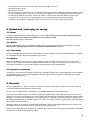
3.1.2. Fitting the Drawbar to the Coupling Unit
Push the square drawbar connection
over the coupling unit attached to the
bicycle.
Insert the spring clip bolt through the
holes of both coupling parts and close
the clip so that the clip opening
surrounds the bolt end.
Please note:
Always attach the safety strap to the
chain stay!
Put the safety tie around the rear section
of the bicycle frame and fasten it to the
drawbar D-ring with the snap hook.
right
wrong

18
5. Service, Care and Storage
5.1. Hitch Arm
Check the hitch arm regularly for signs of damage (e.g. cracks). If there is any kind of damage whatsoever to the hitch arm,
then it must be replaced so as to prevent breakage and the resulting risk of accident.
If in doubt ask your specialist dealer.
• The maximum permissible speed for towing a bicycle trailer is 25 km/h.
• Maximum load 45 kg
• Tyre pressure 2.5 bar
• When used in the dark, bicycle and trailer must be equipped with the correct lighting.
• When parking the outfit make sure it cannot tip over. Attaching a trailer changes the bicycle’s centre of gravity, so that
certain types of kick stands, especially double leg kickstands, cannot be used in connection with a trailer. Tipping over may
damage the trailer, drawbar or the trailer coupling.
• Trailers, even when folded, must not be transported on the roof of a vehicle.
5.2.Wheels
Have the wheels (tyres, rims, tension of spokes, axle bearing) checked by your specialist dealer at least twice a year.
Clean the wheels regularly and give them a protective wax, particularly just before the onset of Winter.
5.3. Fabric Assembly
Clean your CROOZER DOG using water and a rinse agent. Do not use any aggressive cleaning agents as these may perma-
nently damage fabrics und surfaces.
5.4. Storage
Store your CROOZER DOG in a dry and well-ventilated place. Before storing your carrier, it should be dry to prevent the
growth of mould and the formation of marks from mildew. Put your CROOZER DOG as little as possible in direct sunlight to
prevent colours fading. Do not store the trailer coupled to the bicycle over a long period of time.
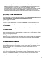
5.5. General Maintenance
Look after your trailer. All painted, chrome or galvanised parts (including screw connectors) should be regularly cleaned and pro-
tected using standard products for this purpose. Ask your specialist dealer about suitable products for protecting your trailer.
6. Warranty
The statutory warranty covers defects. Damage resulting from improper use, use of force, lack of maintenance, or normal wear
and tear, is excluded from such a statutory defect warranty.
The period of statutory warranty depends on the law of the country in question.
Our products have components or parts which are also subject to natural wear and tear arising from normal use, depending
very much on the type and degree of use and also how well the product has been serviced and maintained.
In particular where there has been a lot of use (day in day out and in all kinds of weather), individual parts or components
can reach their wear limit before the statutory guarantee period has expired. Just because a product has become prematurely
worn because of use, it does not automatically mean the product is defective.
For your information we have therefore listed in the following table the important parts affected by wear and tear, and have
named typical contributing factors relating to use, which may considerably influence wear limit.
Irrespective of the type and intensity of use as well as the care and maintenance a functional-related wear occurs in the com-
ponents and parts of a bicycle trailer.

19
Date of issue: 01-2005
www.croozer.info
Reaching the wear limit very much depends on how well the users have looked after and maintained the product as well as
the particular type and intensity of use such as:
•
Mileage in km
•
Effect of load
•
Type of ride
•
Effects of the weather: UV rays, humidity, dirt, temperature, salty air etc.
•
Storage
•
Level of maintenance
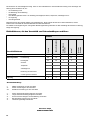
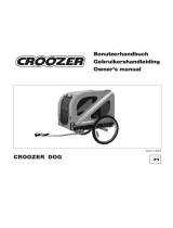
Please look at the following table (‘Wear factors’). You can see from this table which factors particularly affect the wear and tear
on individual parts.
This table complements the existing operation guide – Please do also note the instructions on service, care and storage.
Parts
Wear factors
Loading of: Load xx x xx xx
Influence of the weather: UV rays xx
*1
xx xx
*2
Humidity xx
*3
xx x x
Dirt xx xx x x
Temperature xx x
Salty air x xx xx x xx
Contact with salt water xx xx xxx x xx
Roads gritted with salt xx xx xxx x xx
Storage x x x
*4
Influences on wear and tear:
x: Moderate effect on wear and tear
xx: Strong effect on wear and tear
xxx: Considerable effect on wear and tear
*1 - If at all possible, avoid exposure to strong sun light
*2 - If at all possible, avoid long exposure to sun light
*3 - Avoid mould forming by storage in a dry place
*4 - No wear and tear if stored in a hanging position
*5 - Regularly check the air pressure
Fabric body
Rims,hubs &
spokes
Floor, Side walls
Factors, which particularly increase wear on bicycle trailers:
Drawbar,
Clutch
Tyres
*5

20
Inhoud
Gebruikershandleiding
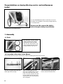
1. Montage ............................................................................................................................................................................................................ 21
1.1. Verpakkingsinhoud ........................................................................................................................................................................................ 21
1.2. De assen in de wielen steken .................................................................................................................................................................... 21
1.3. De wielen loshalen en monteren ............................................................................................................................................................... 22
2. De functie van de aanhanger .................................................................................................................................................................... 22
2.1 De aanhanger uitklappen, vastzetten en opvouwen ........................................................................................................................... 22
2.2 De dissel inklappen ....................................................................................................................................................................................... 23
2.3 Vlag ..................................................................................................................................................................................................................... 24
3. Inbedrijfstelling .............................................................................................................................................................................................. 24
3.1 De dissel aan de fiets bevestigen ............................................................................................................................................................ 24
3.1.1 Het koppelingselement aan de fiets bevestigen .................................................................................................................................. 24
3.1.1.1 Fiets met een volledige as .......................................................................................................................................................................... 24
3.1.1.2 Fiets met een snelspanner ......................................................................................................................................................................... 25
3.1.2 De dissel op het koppelingselement monteren .................................................................................................................................... 26
3.1.3 De lading op de juiste plaats zetten ........................................................................................................................................................ 26
4. Veiligheidsaanwijzingen .............................................................................................................................................................................. 26
5. Onderhoud, verzorging en opslag ........................................................................................................................................................... 27
5.1 Dissel ................................................................................................................................................................................................................. 27
5.2. Wielen ................................................................................................................................................................................................................ 27
5.3. Carrosserie ....................................................................................................................................................................................................... 27
5.4. Opslag ............................................................................................................................................................................................................... 27
5.5. Algemeen onderhoud ................................................................................................................................................................................... 27
6. Garantie ............................................................................................................................................................................................................ 27
Deze handleiding wordt beschermd door de auteurswet en is het eigendom van PRODEK GmbH, Keulen.
Het afdrukken of vermenigvuldigen, ook in gedeelten, van tekst en/of afbeeldingen in wat voor media dan ook,
is alleen toegestaan met schriftelijke toestemming van PRODEK GmbH.
Seite wird geladen ...
Seite wird geladen ...
Seite wird geladen ...
Seite wird geladen ...
Seite wird geladen ...
Seite wird geladen ...
Seite wird geladen ...
Seite wird geladen ...
-
 1
1
-
 2
2
-
 3
3
-
 4
4
-
 5
5
-
 6
6
-
 7
7
-
 8
8
-
 9
9
-
 10
10
-
 11
11
-
 12
12
-
 13
13
-
 14
14
-
 15
15
-
 16
16
-
 17
17
-
 18
18
-
 19
19
-
 20
20
-
 21
21
-
 22
22
-
 23
23
-
 24
24
-
 25
25
-
 26
26
-
 27
27
-
 28
28


Croozer Dog 2008-2013 Bedienungsanleitung
- Typ
- Bedienungsanleitung
in anderen Sprachen
- English: Croozer Dog 2008-2013 Owner's manual
- Nederlands: Croozer Dog 2008-2013 de handleiding
Verwandte Artikel
-
 Croozer Dog Bedienungsanleitung
-
Croozer Cargo Bedienungsanleitung
-
-
 Croozer Vannflaskerlomme Bedienungsanleitung
-
 Croozer Croozer Mini Bedienungsanleitung
-
 Croozer TRAVEL Bedienungsanleitung
-
 Croozer 535 Bedienungsanleitung
-
 Croozer 535 Bedienungsanleitung
-
Croozer Kid for 1 Bedienungsanleitung
-
 Croozer Ski-adapter-set Bedienungsanleitung


