
INFORMATION
KTM PowerParts, HUSQVARNA Husky Power, HUSABERG Pure Tech
KTM - Sportmotorcycle AG
Stallhofnerstraße 3
A-5230 Mattighofen
www.ktm.com
Husqvarna Motorcycles GmbH
Stallhofnerstraße 3
A-5230 Mattighofen
www.husqvarna-motorcycles.com
KTM - Sportmotorcycle AG
Division HUSABERG
Stallhofnerstraße 3
A-5230 Mattighofen
www.husaberg.com
HEATED GRIPS 3.211.703
*3211703*
60112964044 03.2014

Le agradecemos que se haya decidido por este producto.
Este producto de alta calidad está probado para la competición y se ha desarrollado específi camente para las exigencias de este deporte. Para poder
garantizar los máximos niveles de seguridad y funcionalidad, es imprescindible que el producto se monte correctamente. Por este motivo, es muy importante
que siga las instrucciones del manual de montaje o que se ponga en contacto con su concesionario autorizado. El (cuasi) fabricante y el proveedor de este
producto no se harán responsables del montaje y el uso incorrectos.
¡Muchas gracias!
Wir freuen uns, dass Sie sich für dieses Produkt entschieden haben.
Unser hochwertiges Qualitätsprodukt ist rennerprobt und wurde speziell für sportliche Herausforderungen entwickelt. Eine korrekte Montage des
Produktes ist unerlässlich, um ein Maximum an Sicherheit und Funktionalität gewährleisten zu können. Bitte befolgen Sie daher die Montageanleitung
oder wenden Sie sich an Ihren autorisierten Fachhändler. Für falsche Montage oder Verwendung dieses Produktes kann der (Quasi) Hersteller bzw.
Lieferant nicht zur Verantwortung gezogen werden.
Vielen Dank.
Thank you for choosing this product.
Our high quality product has been tested under racing conditions and was developed specifi cally for use in sports activities. Correct installation of the pro-
duct is essential to ensure that a maximum degree of safety and functionality is achieved. Therefore, please follow the installation instructions or contact
your authorized dealer. The (quasi) manufacturer or supplier cannot be held responsible for products that are incorrectly mounted or inappropriately used.
Thank you.
Grazie per aver scelto questo prodotto.
Questo nostro prodotto di pregiata qualità è collaudato nelle competizioni ed è stato sviluppato specifi camente per gare sportive. Il montaggio corretto del
prodotto è fondamentale per garantirne la massima sicurezza e funzionalità. Rispettare quindi le istruzioni di montaggio o rivolgersi al proprio concessio-
nario autorizzato. Il produttore (detentore del marchio)/fornitore non può essere considerato responsabile per un montaggio o impiego errato del presente
prodotto.aVi ringraziamo per l’attenzione!
Merci d‘avoir porté votre choix sur ce produit.
Notre produit de haute qualité est éprouvé pour les compétitions et a été conçu spécialement pour un usage sportif. Un montage approprié du produit
est indispensable pour garantir une sécurité et une fonctionnalité maximales du véhicule. C‘est pourquoi nous vous invitons à suivre scrupuleusement le
manuel de montage ou à vous adresser à votre revendeur agréé. En cas de montage ou d‘utilisation non conformes de ce produit, le (quasi )constructeur
ou le fournisseur déclinent toute responsabilité.
Merci !
5 ENGLISH
7 ITALIANO
9 FRANCAIS
11 ESPANOL
3 DEUTSCH

DEUTSCH
3
Lieferumfang
HEIZGRIFFKIT 60112964044
1x Festgriff mit Heizung
1x Drehgriffüberzug mit Heizung
1x Schalter komplett 60112964040
1x Schalterbefestigung
1x Schelle Schalterbefestigung
1x Doppelklebeband 26x26mm
1x Gummistreifen
2x Zylinderschraube M5x15
2x Sicherungsscheibe
2x Kabelband 3,5 x 145
1x Buchse 8,5x20x8 (Handguard)
1x Zylinderschraube M8x50
1x Buchse 14x20x8 (Vibrationsdämpfer)
Montage
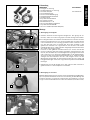
1. Befestigung der Heizgriffe
aZunächst entfernen Sie die originalen Griffgummis. Dies gelingt am ein-
fachsten, indem Sie sie vorsichtig (quer zur Fahrtrichtung) aufschneiden.
bDie Heizgriffe haben verschiedene Innendurchmesser. Der Griff mit dem
kleineren Innendurchmesser (ca. 22mm) wird über das (in Fahrtrichtung)
linke Lenkerende bis zum Anschlag geschoben. Dabei ist darauf zu ach-
ten, dass der Griff gleich so ausgerichtet wird, dass die Kabel in der
gewünschten Position zum Liegen kommen und vor dem Aufschieben
KTM-Griffkleber Art.Nr. 6.899.792 dünn aufgetragen wird (auf Fettfreiheit
von Lenker und Heizgriff achten).
Der Griff mit dem größeren Innendurchmesser (ca. 24mm) wird auf der
rechten Lenkerseite über den Gasgriff geschoben. Positionieren Sie den
Griff so, dass das Kabel (1) in keiner Gasgriffstellung hängen bleiben kann
und sichern Sie es mit den Gummi-Kabelbindern an den Kabelsträngen.
Auch hier vor dem Aufschieben KTM-Griffkleber Art.Nr. 6.899.792 dünn
auftragen und auf Fettfreiheit von Gas- und Heizgriff achten. Vor der
Montage der Rallyeguards die Zwischenbuchse (2) zwischen Lenker und
Rallyeguard beilegen und mit der mitgelieferten Zylinderschraube M8x50
befestigen.
cKontrollieren Sie, ob der Gasgriff leicht läuft und nach dem Loslassen in
gewohnter Weise in die Ruheposition zurückkehrt.
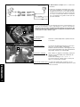
2. Befestigung des Schalters
Doppelklebeband (3) zwischen Schalter und Schalterbefestigung (4) anbrin-
gen. Für optimale Klebekraft sollten Sie die Halterung vor der Montage des
Schalters entfetten. Die gesamte Schaltereinheit anschließend in einer für
Sie gut zu erreichenden Position am Lenker verschrauben (siehe Bild unten).
1
2
4
3

DEUTSCH
4
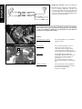
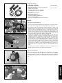
bDer schwarz/rote Anschluß dient der Stromversorgung. Verbinden Sie diesen
mit dem freistehenden Stecker “ACC2” (5) (rot +, schwarz -) am Fahrzeug.
Dieser Stecker liefert nur bei eingeschalteter Zündung Strom und verhindert
so, dass sich die Batterie entlädt, wenn die Heizgriffe nach dem Abstellen
des Motors nicht ausgeschaltet werden.
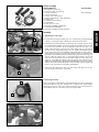
4. Funktion
Einschalten/Ausschalten: den Schalter (6) für ca. 3 Sekunden
gedrückt halten.
Schnellstart: Die Schnellstartfunktion ist für 4
Minuten nach dem Start aktiv.
In der Zeit blinkt die gespeicherte
LED anzeige.Zum Ausschalten der
Schnellstartfunktion Knopf (6) drücken.
Heizstufen: Zum Ändern der Heizstufe den
Knopf (6) wiederholt drücken bis die
gewünschte Heizstufe gewählt ist.
Heizstufen 1 > 2 > 3 > 4 > 1
Die Led der gewählten Heizstufe
leuchtet für die ersten 2-3 Sekunden
auf.
Memory Funktion: Die Heizstufe der zuletzt gewählten
Einstellung wird gespeichert und bei
der nächsten Verwendung
automatisch gewählt.
3. Elektrischer Anschluß (siehe Anschlußskizze)
aVerbinden Sie die Heizgriffe mit dem Schalter,
wie im Schaltplan dargestellt. Verlegen und
fixieren Sie die Kabel so an den Seilzügen und
am Cockpitträger, dass sie genügend Spiel haben
und nicht scheuern. Auch die Freigängigkeit des
Lenkers muss erhalten bleiben.
Schalter
links
rechts
5
6

ENGLISH
5
1
2
4
3
Scope of supply
HEATED GRIP KIT 60112964044
1x fixed grip with heating
1x twist grip cover with heating
1x switch, complete 60112964040
1x switch attachment
1x clamp, switch attachment
1x double-sided adhesive tape 26x26mm
1x rubber strip
2x cap head screws M5x15
2x lock washers
2x cable ties 3.5 x 145
1x bushing 8.5x20x8 (handguard)
1x cap head screw M8x50
1x bushing 14x20x8 (vibration damper)
Assembly
1. Attaching the heated grip
aFirst remove the original rubber grips. This is most easily accomplished by
carefully cutting them open (transverse to the direction of travel).
bThe heated grips have different inside diameters. The grip with the smal-
ler inside diameter (approx. 22 mm) is slipped all the way over the left end
(in the direction of travel) of the handlebar. Ensure that the grip is ori-
ented, from the outset, such that the cable comes to rest in the correct
position. Thinly apply KTM grip glue art. no. 6.899.792 before slipping
on the grip (ensure that the handlebar and heated grip are grease-free).
The grip with the larger inside diameter (approx. 24mm) is slipped on the
right end of the handlebar over the throttle twist grip. Position the grip so
that the cable (1) cannot catch in any throttle grip position. Secure the
cable to the wiring harnesses with the rubber cable ties. Here, too, thinly
apply art. no. 6.899.792 before sliding on the grip and ensure that the
throttle grip and heated grip are grease-fee. Before mounting the rally guards,
add the intermediate bush (2) between the handlebar and rally guard and
fasten it with the supplied cap head screw M8x50.
cCheck that the throttle twist grip can move easily and returns to its nor-
mal resting position when it is released.
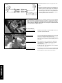
2. Attaching the switch
Attach the double-sided adhesive tape (3) between the switch and switch
attachment (4). For the best adhesive force, degrease the holder before
mounting the switch. Then screw the entire switch unit into a position on
the handlebar that you can easily reach (see figure below).

ENGLISH
6
5
6
bThe black/red connection provides the power supply. Connect it with the vacant
connector “ACC2” (5) (red +, black -) on the vehicle. This connector only
supplies power when the ignition is switched on and thus prevents draining
of the battery if the heated grips are not switched off after the engine is swit-
ched off.
4. Function
To switch on/off: Press the switch (6) for approx. 3 seconds.
Quick start: The quick start function is active for 4 minutes after the start.
During this period, the stored LED display flashes. To switch
off the quick start function, press button (6).
Heating levels: To change the heating level, press button (6) repeatedly until
you reach the required heating level.
Heating levels 1 > 2 > 3 > 4 > 1
The LED of the selected heating level lights up for the first
2-3 seconds.
Memory function: The heating level of the last setting is stored and automa
tically selected the next time the heated grips are used.
3. Electrical connection (see connection diagram)
aConnect the heated grips with the switch as
shown in the wiring diagram. Route and secure
the cables on the existing cables and cockpit
carrier in such a way that there is enough play
and no chafing. Freedom of movement of the
handlebar must be retained as well.
Switch
Left
Right

ITALIANO
7
1
2
4
3
Volume della fornitura
KIT MANOPOLE RISCALDABILI 60112964044
N. 1 manopola fissa con riscaldamento
N.1 manopola del comando del gas con riscaldamento
N. 1 interruttore completo 60112964040
N. 1 dispositivo di fissaggio dell’interruttore
N. 1 fascetta per il dispositivo di fissaggio dell’interruttore
N. 1 nastro biadesivo 26x26mm
N. 1 fascetta in gomma
N. 2 viti a testa cilindrica M5x15
N. 2 rondelle di sicurezza
N. 2 fascette serracavi 3,5 x 145
N. 1 boccola 8,5x20x8 (paramano)
N. 1 vite a testa cilindrica M8x50
N. 1 boccola 14x20x8 (ammortizzatore di vibrazioni)
Montaggio
1. Fissaggio delle manopole riscaldabili
aPrima di tutto rimuovere le manopole originali. Il modo più semplice per
rimuoverle consiste nel tagliarle delicatamente (trasversalmente rispetto
alla direzione di marcia).
bLe manopole riscaldabili presentano diametri interni diversi. La manopola
con il diametro interno più piccolo (ca. 22 mm) va spinta fino a battuta
sull’estremità sinistra del manubrio (guardando in direzione di marcia),
facendo attenzione a posizionare correttamente i cavi. Prima di infilare la
manopola, applicare un sottile strato di colla per manopole KTM cod.art.
6.899.792 (il manubrio e la manopola riscaldabile devono essere privi di
grasso).
Spingere la manopola con il diametro interno più grande (ca. 24 mm)
sull’estremità destra del manubrio, sopra il comando del gas. Posizionare
la manopola in modo che il cavo (1) non possa impigliarsi nel comando
del gas e fissarlo ai cablaggi con le fascette serracavo in gomma. Anche
in questo caso, prima di infilare la manopola controllare che il comando
del gas e la manopola riscaldabile siano privi di grasso e applicare un sot-
tile strato di colla per manopole KTM cod.art. 6.899.792. Prima di mon-
tare i paramani Rally, frapporre tra il manubrio e il paramano la boccola
intermedia (2) e fissare il paramano con la vite a testa cilindrica M8x50
fornita in dotazione.
cControllare che il comando del gas sia scorrevole e che quando viene rilas-
ciato ritorni nella sua posizione di riposo.
2. Fissaggio dell’interruttore
Applicare il nastro biadesivo (3) tra l’interruttore e il dispositivo di fissaggio
dell’interruttore (4). Per ottimizzare l’aderenza, prima di montare l’interrut-
tore sgrassare il supporto. Avvitare quindi l’interruttore completo in una posi-
zione facilmente raggiungibile sul manubrio (vedi foto in basso).

ITALIANO
8
5
6
bIl contatto nero/rosso serve per l’alimentazione elettrica. Collegarlo al con-
nettore libero "ACC2" (5) (rosso +, nero -) sul veicolo. Questo connettore for-
nisce corrente solo ad accensione inserita, evitando così che la batteria si
scarichi nel caso in cui si spenga il motore dimenticando di disinserire le
manopole riscaldabili.
4. Funzionamento
Inserimento/disinserimento:Tenere premuto l’interruttore (6) per ca. 3 secondi.
Avvio rapido: La funzione di avvio rapido rimane attivare per 4
minuti dopo l’avvio.
Durante questo arco di tempo il LED del livello di
riscaldamento salvato lampeggia. Per disinserire la
funzione di avvio rapido, premere il pulsante (6).
Livelli di riscaldamento: Per modificare il livello di riscaldamento premere
ripetutamente il pulsante (6) fino a selezionare il
livello desiderato.
Livelli di riscaldamento 1 > 2 > 3 > 4 > 1
Il led del livello di riscaldamento selezionato si
accende per i primi 2-3 secondi.
Funzione Memory: L’ultimo livello di riscaldamento selezionato viene
memorizzato e impostato automaticamente al suc
cessivo utilizzo.
3. Collegamento elettrico (vedi schema di colle-
gamento)
aCollegare le manopole riscaldabili con l’inter-
ruttore, come rappresentato nello schema elet-
trico. Sistemare e fissare i cavi ai comandi a cavo
flessibile e al porta cruscotto, in modo che
abbiano sufficiente gioco e che non sfreghino
da nessuna parte. Assicurarsi che non intralcino
la regolare corsa del manubrio.
Interruttore
sinistra
destra

FRANCAIS
9
1
2
4
3
Contenu de la livraison :
KIT POIGNÉES CHAUFFANTES 60112964044
1x poignée fixe avec chauffage
1x couche de manette tournante avec chauffage
1x bouton de commande complet 60112964040
1x fixation du bouton de commande
1x collier de fixation du bouton de commande
1x double bande adhésive 26x26mm
1x bande en caoutchouc
2x vis à tête cylindrique M5x15
2x rondelle d’arrêt
2x collier pour câbles 3,5 x 145
1x bague 8,5x20x8 (protection de main)
1x vis à tête cylindrique M8x50
1x bague 14x20x8 (amortisseur de vibrations)
Montage
1. Fixation des poignées chauffantes
aCommencer par retirer les poignées caoutchouc d’origine. On y arrive faci-
lement en découpant soigneusement le caoutchouc dans le sens de la
longueur.
bLes deux poignées chauffantes ont des diamètres intérieurs différents. La
poignée avec le petit diamètre intérieur (env. 22 mm) doit être enfilée à
gauche sur le guidon (vu dans le sens de marche) jusqu’en butée. Lors de
cette opération, veiller à ce que les câbles prennent la position souhaitée,
et appliquer au préalable de la colle KTM réf. 6.899.792 en fine couche
(veiller à ce que le guidon et la poignée chauffante soient exempts de graisse).
Enfiler la poignée avec le diamètre intérieur le plus grand (env. 24 mm) à
droite sur le guidon, par dessus la poignée d’accélération. Placer la poi-
gnée de sorte que le câble (1) ne puisse pas rester coincé, quelle que soit
la position de la poignée d’accélération et attacher ce câble au faisceau
avec des serre-câble. Là aussi, appliquer préalablement une fine couche
de colle KTM réf. 6.899.792 et veiller à ce que la poignée d’accélération
et la poignée chauffante soient exemptes de graisse. Avant de monter les
protège-main, placer la bague intermédiaire (2) entre la poignée et le pro-
tège-main et fixer le tout avec la vis à tête cylindrique M8x50 fournie dans
le kit.
cVérifier que la poignée d’accélération peut tourner aisément et revenir en
position de repos après relâchement.
2. Fixation du bouton de commande
Mettre une bande adhésive double face (3) entre le bouton et le support de
fixation du bouton(4). Nettoyer soigneusement la fixation avant d’y coller le
bouton, pour permettre une parfaite adhérence. Visser le bloc de bouton de
commande complet sur le guidon dans une position facilement accessible
au pilote (voir la figure ci-dessous).

FRANCAIS
10
5
6
bLa cosse noire/rouge permet l’alimentation électrique. Le branchement s’ef-
fectue sur la fiche libre « ACC2 » (5) (rouge au +, noir au -) du véhicule.
Cette fiche est sous tension seulement quand l’allumage est enclenché, afin
d’éviter une décharge de la batterie lorsque les poignées chauffantes restent
enclenchées une fois le moteur coupé.
4. Fonctionnement
Marche/arrêt :Maintenir le bouton (6) enfoncé pendant environ
3 secondes.
Démarrage rapide :La fonction de démarrage rapide est activée pen
dant env. 4 minutes après le démarrage.
Pendant la durée d’activation, l’affichage LED enre
gistré clignote. Pour désactiver la fonction de démar
rage rapide, appuyer sur le bouton (6).
Niveaux de chauffage :Pour modifier le degré de réchauffage, appuyer à
nouveau sur le bouton (6) jusqu’à obtention du
niveau souhaité.
Niveaux de chauffage 1 > 2 > 3 > 4 > 1
La led du niveau de chauffe choisi s’allume pen
dant les 2-3 premières secondes.
Fonction de mémorisation :Le niveau de chauffe réglé en dernier lieu est
mémorisé et sélectionné automatiquement à la pro
chaine utilisation.
3. Branchement électrique (voir le schéma de
connexion)
aConnecter les poignées chauffantes avec le bou-
ton, comme indiqué sur le schéma de câblage.
Disposer et fixer les fils sur les câbles de com-
mande et sur la planche de cockpit, de manière
à ce qu’ils ne soient pas bridés et ne frottent
pas La manoeuvre du guidon ne doit pas non
plus être entravée.
Bouton de commande
à gauche
à droite

ESPANOL
11
1
2
4
3
Volumen de suministro
KIT DE PUÑOS TÉRMICOS 60112964044
1 puño fijo con calefacción
1 revestimiento de puño giratorio con calefacción
1 interruptor completo 60112964040
1 fijación para interruptor
1 abrazadera para fijación de interruptor
1 cinta adhesiva de dos caras 26x26mm
1 tira de goma
2 tornillos cilíndricos M5x15
2 arandelas de retención
2 cintas sujetacables 3,5x145
1 casquillo 8,5x20x8 (guardamanos)
1 tornillo cilíndrico M8x50
1 casquillo 14x20x8 (amortiguador de vibraciones)
Montaje
1. Fijación de los puños térmicos
aEn primer lugar, retirar los puños de goma originales. La manera más fácil
es cortarlas con cuidado y en dirección perpendicular a la marcha.
bLos puños térmicos tienen diámetros interiores diferentes. El puño con el
diámetro interior más pequeño (aprox. 22 mm) debe colocarse hasta el
tope en el extremo izquierdo del manillar (en la dirección de la marcha).
Procure que el puño esté colocado de modo que los cables queden en la
posición correcta. Además, antes de insertarlo, debe comprobarse que el
manillar y el puño térmico estén limpios de grasa y debe untarse con una
capa fina de adhesivo para puños KTM (ref. 6.899.792).
El puño con el diámetro interior más grande (aprox. 24 mm) debe colo-
carse sobre el puño del acelerador, en el lado derecho del manillar. Colocar
el puño de manera que el cable (1) no quede colgando en ninguna posi-
ción del puño del acelerador y, acto seguido, sujetar el cable a los rama-
les de cables con la cinta sujetacables de goma. También en este caso,
antes de colocar el puño, debe comprobarse que el puño del acelerador y
el puño térmico estén limpios de grasa y debe aplicarse una capa fina de
adhesivo para puños KTM (ref. 6.899.792). Antes de montar el guarda-
manos para rally, colocar el casquillo intermedio (2) entre el manillar y el
guardamanos para rally y fijarlo con el tornillo cilíndrico M8x50 suminis-
trado.
cComprobar que el puño del acelerador se mueva con suavidad y que, al
soltarlo, regrese a la posición de reposo con normalidad.
2. Fijación del interruptor
Colocar cinta adhesiva de dos caras (3) entre el interruptor y la fijación (4).
Para lograr una fuerza de adhesión óptima, antes de montar el interruptor
debe desengrasarse el soporte. A continuación, atornillar toda la unidad del
interruptor en un lugar del manillar cómodo para usted (véase la figura infe-
rior).

ESPANOL
12
5
6
bLa conexión de color negro/rojo es la alimentación eléctrica. Esta conexión
debe conectarse al conector libre "ACC2" (5) (rojo +, negro -) del vehículo.
Este conector solo suministra electricidad cuando el encendido está conectado,
lo que evita que la batería se descargue en caso de que los puños térmicos
no se desactiven al apagar el motor.
4. Funcionamiento
Encendido y apagado: Mantener presionado el interruptor (6) durante 3
segundos aproximadamente.
Arranque rápido: La función de arranque rápido permanece activada
durante 4 minutos después de arrancar.
Durante ese tiempo, el indicador LED parpadea. Para
desactivar la función de arranque rápido, pulsar el
botón (6).
Niveles de calefacción: Para cambiar el nivel de calefacción, presionar
repetidamente el botón (6) hasta seleccionar el
nivel deseado.
Niveles de calefacción: 1 > 2 > 3 > 4 > 1.
El LED del nivel seleccionado se ilumina durante
los 2-3 primeros segundos.
Función de memoria: El último nivel de calefacción seleccionado queda
memorizado y se selecciona automáticamente la pró
xima vez que se vuelva a utilizar el sistema.
3. Conexión eléctrica (véase el esquema de cone-
xiones)
aConectar los puños térmicos al interruptor tal
como se muestra en el esquema de conexiones.
Tender y fijar los cables junto a los cables de
tracción y en el soporte del tablero de mandos,
dejando holgura suficiente y asegurándose de
que no se produzcan roces. Asimismo, el manil-
lar debe poder moverse libremente.
Interruptor
Izquierda
Derecha
-
 1
1
-
 2
2
-
 3
3
-
 4
4
-
 5
5
-
 6
6
-
 7
7
-
 8
8
-
 9
9
-
 10
10
-
 11
11
-
 12
12


in anderen Sprachen
- English: KTM 60112964044 Owner's manual
- français: KTM 60112964044 Le manuel du propriétaire
- español: KTM 60112964044 El manual del propietario
- italiano: KTM 60112964044 Manuale del proprietario
Verwandte Artikel
-
KTM 60312964044 Bedienungsanleitung
-
-
-
-
-
KTM 7650297900028 Bedienungsanleitung
-
-
-
-
