
INFORMATION
KTM PowerParts, HUSQVARNA Husky Power, HUSABERG Pure Tech
KTM - Sportmotorcycle AG
Stallhofnerstraße 3
A-5230 Mattighofen
www.ktm.com
Husqvarna Motorcycles GmbH
Stallhofnerstraße 3
A-5230 Mattighofen
www.husqvarna-motorcycles.com
KTM - Sportmotorcycle AG
Division HUSABERG
Stallhofnerstraße 3
A-5230 Mattighofen
www.husaberg.com
ALUMINIUM HANDGUARDS
3.211.704
*3211704*
7650297910004
7650297900028
7650297910030
12.2013

Le agradecemos que se haya decidido por este producto.
Este producto de alta calidad está probado para la competición y se ha desarrollado específi camente para las exigencias de este deporte. Para poder
garantizar los máximos niveles de seguridad y funcionalidad, es imprescindible que el producto se monte correctamente. Por este motivo, es muy importante
que siga las instrucciones del manual de montaje o que se ponga en contacto con su concesionario autorizado. El (cuasi) fabricante y el proveedor de este
producto no se harán responsables del montaje y el uso incorrectos.
¡Muchas gracias!
Wir freuen uns, dass Sie sich für dieses Produkt entschieden haben.
Unser hochwertiges Qualitätsprodukt ist rennerprobt und wurde speziell für sportliche Herausforderungen entwickelt. Eine korrekte Montage des
Produktes ist unerlässlich, um ein Maximum an Sicherheit und Funktionalität gewährleisten zu können. Bitte befolgen Sie daher die Montageanleitung
oder wenden Sie sich an Ihren autorisierten Fachhändler. Für falsche Montage oder Verwendung dieses Produktes kann der (Quasi) Hersteller bzw.
Lieferant nicht zur Verantwortung gezogen werden.
Vielen Dank.
Thank you for choosing this product.
Our high quality product has been tested under racing conditions and was developed specifi cally for use in sports activities. Correct installation of the pro-
duct is essential to ensure that a maximum degree of safety and functionality is achieved. Therefore, please follow the installation instructions or contact
your authorized dealer. The (quasi) manufacturer or supplier cannot be held responsible for products that are incorrectly mounted or inappropriately used.
Thank you.
Grazie per aver scelto questo prodotto.
Questo nostro prodotto di pregiata qualità è collaudato nelle competizioni ed è stato sviluppato specifi camente per gare sportive. Il montaggio corretto del
prodotto è fondamentale per garantirne la massima sicurezza e funzionalità. Rispettare quindi le istruzioni di montaggio o rivolgersi al proprio concessio-
nario autorizzato. Il produttore (detentore del marchio)/fornitore non può essere considerato responsabile per un montaggio o impiego errato del presente
prodotto.aVi ringraziamo per l’attenzione!
Merci d‘avoir porté votre choix sur ce produit.
Notre produit de haute qualité est éprouvé pour les compétitions et a été conçu spécialement pour un usage sportif. Un montage approprié du produit
est indispensable pour garantir une sécurité et une fonctionnalité maximales du véhicule. C‘est pourquoi nous vous invitons à suivre scrupuleusement le
manuel de montage ou à vous adresser à votre revendeur agréé. En cas de montage ou d‘utilisation non conformes de ce produit, le (quasi )constructeur
ou le fournisseur déclinent toute responsabilité.
Merci !
2 ENGLISH
2 ITALIANO
2 FRANCAIS
2 ESPANOL
2 DEUTSCH

DEUTSCH
3
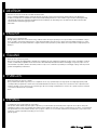
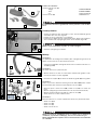
Vorarbeiten
- Die Enden der Griffgummi (ca. 3mm vom Rand gemessen) links und rechts
mit einem scharfem Messer abschneiden.
- Griffgummi am Gasgriff etwas zurückstülpen.
- Schrauben (4) lösen und Gasgriff ca. 20mm nach außen schieben.
- Das Ende des Gasgriffes (ca. 3mm vom Rand gemessen) absägen (Bild A).
Lenker beim Sägen nicht beschädigen.
- Kanten des Gasgriffs bei Bedarf entgraten.
Lieferumfang:
2x Handschutz (1)
orange 7650297905004
weiß 7650297905028
schwarz 7650297905030
2x Alubügel (2) 76502979144
Diese Handschützer gewährleisten keinen Schutz vor Verletzungen.
Montage
HINWEIS:
Die Montage gilt sowohl für die linke als auch für die rechte Seite. Schrauben
nicht überziehen.
- Schraube (5) durch die Bohrung im Alubügel schieben und mit dem Einsatz
(6) montieren (Bild B).
HINWEIS:
Schraube nur leicht anbeißen lassen.
- Die Alubügel mit den Einsätzen in das Lenkerende montieren und vorerst
nur handfest anziehen (Bild B).
- Schrauben (7) und (8) lösen und Lenkerklemmen (9) am Lenker montie-
ren.
HINWEIS:
Wählen Sie das passende links oder rechts gekröpfte Schellenverbindungsstück
(9b) nach Bedarf aus, um den Bügel mit der Schelle (9a) zu verbinden.
- Die Alubügel (10) positionieren und Schraube (11) montieren und vorerst
nur handfest anziehen.
- Gasgriff ordnungsgemäß montieren (Nm siehe Bedienungsanleitung).
- Handschützer (1) auf die Alubügel (10) montieren.
- Sämtliche Schrauben in folgender Reihenfolge festziehen:
HINWEIS:
Vor dem Festziehen der Schrauben, Handschutz in Endposition bringen.
- Schraube (11) festziehen.
- Schraube (8) festziehen.
- Schraube (7) festziehen.
- Restliche Schrauben festziehen.
Schraubverbindungen nochmals kontrollieren und sämtliche Bedienelemente,
insbesondere Kupplung, Bremse und Gas auf ordnungsgemäße Funktion
prüfen.
Leichtgängigkeit und Funktionalität aller Bedienelemente sind regelmäßig
zu überprüfen.
1
1
2
4
4
A
B
5
7
11
6
10
8
9a 9b

ENGLISH
4
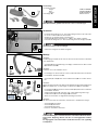
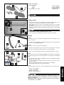
Preparations
- Cut off the ends of the left and right rubber grips (approx. 3 mm from the
edge) with a sharp knife.
- Push back the rubber grip on the throttle twist grip somewhat.
- Release the screws (4) and slide the throttle twist grip outward by approx.
20 mm.
- Saw off the end of the throttle twist grip (approx. 3 mm from the edge)
(Figure A).
Do not damage the handlebar when sawing.
- Deburr the edges of the throttle twist grip if necessary.
Scope of supply:
2x hand guards (1)
orange 7650297905004
white 7650297905028
black 7650297905030
2x aluminum brackets (2) 76502979144
These hand guards do not provide protection against injury.
Assembly
NOTE:
The assembly steps apply to both the left and right sides. Do not overtighten
screws.
- Insert screw (5) through the drilled hole in the aluminum bracket and mount
with the insert (6) (Figure B).
NOTE:
Let the screw engage only slightly.
- Mount the aluminum bracket with the inserts into the handlebar end and
initially tighten hand-tight only (Figure B).
- Release screws (7) and (8) and mount the handlebar clamps (9) on the
handlebar.
NOTE:
Choose the clamp connection part (9b) with offset to the left or right depen-
ding on what is needed to connect the backbone to clamp (9a).
- Position the aluminum bracket (10) and mount the screw (11), initially
tightening hand-tight only.
- Properly mount the throttle twist grip (for Nm, see the Owner's Manual).
- Mount the hand protector (1) on the aluminum bracket (10).
- Tighten all screws in the following order:
NOTE:
Before tightening the screws, move the hand guard into its final position.
- Tighten the screw (11).
- Tighten the screw (8).
- Tighten the screw (7).
- Tighten the remaining screws.
Check the screw connections again and ensure that all control elements, espe-
cially the coupling, brake and throttle, are functioning properly.
Smooth operation and correct functioning of the controls need to be che-
cked regularly.
1
1
2
4
4
A
B
5
6
7
11
10
8
9a 9b

ITALIANO
5
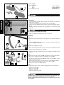
Operazioni preliminari
- Con una lama affilata tranciare l'estremità della manopola (ca. 3 mm dal
bordo) a sinistra e a destra.
- Rimboccare parte della manopola sul comando del gas.
- Svitare le viti (4) e spingere la manopola del comando del gas di ca.
20 mm verso l'esterno.
- Tagliare l'estremità della manopola del comando del gas (ca. 3 mm dal
bordo) (figura A).
Nel segare i vari elementi prestare attenzione a non danneggiare il manubrio.
- Se necessario sbavare i bordi della manopola del comando del gas.
Volume della fornitura:
N. 2 paramani (1)
arancio 7650297905004
bianco 7650297905028
nero 7650297905030
N. 2 staffe in alluminio (2) 76502979144
Questi paramani non escludono il rischio di lesioni.
Montaggio
NOTA:
Il montaggio vale sia per il lato sinistro, che per quello destro. Non serrare
eccessivamente le viti.
- Spingere la vite (5) attraverso il foro della staffa in alluminio e montarla con
l'inserto (6) (figura B).
NOTA:
La vite deve ingranare solo leggermente.
- All'estremità del manubrio montare le staffe in alluminio con gli inserti,
serrando momentaneamente solo a mano (figura B).
- Svitare le viti (7) e (8) e montare i morsetti (9) sul manubrio.
NOTA:
Scegliete un connettore del morsetto (9b) con deviazione a sinistra o a destra
a seconda di cosa serve per collegare la barra al morsetto (9a).
- Posizionare le staffe in alluminio (10) e montare la vite (11), serrandola
momentaneamente solo a mano.
- Montare la manopola del comando del gas (i valori relativi ai Nm da appli-
care sono riportati nel manuale d'uso).
- Montare i paramani (1) sulle staffe in alluminio (10).
- Serrare tutte le viti nel seguente ordine:
NOTA:
Prima di serrare le viti, portare il paramano in posizione finale.
- Serrare la vite (11).
- Serrare la vite (8).
- Serrare la vite (7).
- Serrare le restanti viti.
Controllare ancora una volta i collegamenti a vite e assicurarsi che tutti gli
elementi di comando funzionino correttamente, in particolare frizione, freno
e comando del gas.
Periodicamente controllare la scorrevolezza e il funzionamento di tutti gli ele-
menti di comando.
1
1
2
4
4
A
B
5
6
7
11
10
8
9a 9b

FRANCAIS
6
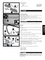
Travaux préalables
- Couper les extrêmités des caoutchoucs (à env. 3mm du bord) de gauche
et de droite avec une lame aiguisée.
- Décaler un peu le caoutchouc sur la poignée.
- Desserer les vis (4) et pousser la poignée gaz d'env. 20mm vers l'extérieur.
- Scier l'extrêmité de la poignée gaz (à env. 3mm du bord) (figure A).
Veiller à ne pas endommager le guidon en sciant la poignée.
- Ebavurer la poignée gaz au besoin.
Contenu de la livraison :
2x Protection de main (1)
orange 7650207905030
blanc 7650207905004
noir 7650297905030
2x Etrier en alu (2) 76502979144
Ces protections de main ne garantissent aucune protection contre les bles-
sures.
Montage
REMARQUE :
Ces opérations de montage sont valables pour la poignée de gauche et de
droite. Ne pas serrer les vis de manière excessive.
- Enfoncer la vis (5) dans l'alésage de l'étrier en alu et insérer le tout avec l'in-
sert (6) (figure B).
REMARQUE :
Ne laisser sortir la vis que de très peu.
- Monter l'étrier en alu avec les inserts dans l'extrêmité du guidon et com-
mencer par serrer à la main (figure B).
- Desserrer les vis (7) et (8) et monter les brides du guidon (9) sur le guidon.
REMARQUE :
Choisir la pince de connexion version gauche ou droite (9b) selon ce dont
on aura besoin pour connecter l'épine dorsale à la pince (9a).
- Mettre en place l''étrier en alu (10), insérer la vis (11) et la serrer à la
main.
- Monter la poignée gaz correctement (Nm voir le manuel d'utilisation).
- Monter les protections de main (1) sur l'étrier en alu (10).
- Serrer toutes les vis dans l'ordre suivant :
REMARQUE :
Avant de serrer les vis, mettre la protection de main en position de butée.
- Serrer la vis (11).
- Serrer la vis (8).
- Serrer la vis (7).
- Serrer le reste des vis.
Vérifier à nouveau les assemblages vissés et contrôler tous les éléments de
commande, en particulier l'embrayage, le frein et la manette des gaz.
Vérifier régulièrement la souplesse et le fonctionnement de tous les éléments
de commande.
1
1
2
4
4
A
B
5
6
7
11
10
8
9a 9b

ESPANOL
7
Trabajos previos
- Cortar los extremos de las empuñaduras de goma (medido a aprox. 3 mm
del borde) a la izquierda y la derecha con un cutter afilado.
- Girar ligeramente hacia atrás las empuñaduras de goma en el puño del
acelerador.
- Soltar los tornillos (4) y mover el puño del acelerador aprox. 20 mm hacia fuera.
- Cortar el extremo del puño del acelerador (medido a aprox. 3 mm del borde)
(figura A).
Tener cuidado de no dañar el manillar durante el corte.
- Si fuera necesario, desbarbar los bordes del puño del acelerador.
Volumen de suministro:
2x guardamanos (1)
naranja 7650297905004
blanco 7650297905028
negro 7650297905030
2x estribos de aluminio (2) 76502979144
Estos guardamanos no son una garantía de protección contra lesiones.
Montaje
NOTA:
El montaje es igual para los lados izquierdo y derecho. No apretar los tor-
nillos en exceso.
- Introducir el tornillo (5) por el taladro del estribo de aluminio y montarlo con
la pieza intercalada (6) (figura B).
NOTA:
Dejar que el tornillo solo penetre ligeramente.
- Montar los estribos de aluminio con las piezas intercaladas en el extremo
del manillar y apretarlos primero solo con la mano (figura B).
- Soltar los tornillos (7) y (8) y montar las abrazaderas (9) en el manillar.
NOTA:
Elija la pieza conectora de la abrazadera (9b) que sobresalga hacia la izquierda
o la derecha según sea necesario para conectar la estructura a la abrazadera
(9a).
- Colocar los estribos de aluminio (10) y montar el tornillo (11) apretándolo
primero solo con la mano.
- Montar el puño del acelerador correctamente (véanse los Nm en el manual
de instrucciones).
- Montar los guardamanos (1) en los estribos de aluminio (10).
- Apretar todos los tornillos en el siguiente orden:
NOTA:
Antes de apretar los tornillos, colocar el guardamanos en la posición final.
- Apretar el tornillo (11).
- Apretar el tornillo (8).
- Apretar el tornillo (7).
- Apretar el resto de tornillos.
Volver a controlar las uniones atornilladas y comprobar que todos los ele-
mentos de mando funcionen correctamente, en especial el embrague, los
frenos y el acelerador.
Comprobar de manera regular que todos los elementos de mando funcionen
correctamente y con suavidad.
1
1
2
4
4
A
B
5
6
7
11
10
8
9a 9b
-
 1
1
-
 2
2
-
 3
3
-
 4
4
-
 5
5
-
 6
6
-
 7
7


KTM 7650297900028 Bedienungsanleitung
- Typ
- Bedienungsanleitung
- Dieses Handbuch eignet sich auch für
in anderen Sprachen
- English: KTM 7650297900028 Owner's manual
- français: KTM 7650297900028 Le manuel du propriétaire
- español: KTM 7650297900028 El manual del propietario
- italiano: KTM 7650297900028 Manuale del proprietario
Verwandte Artikel
-
KTM 7650297900004 Bedienungsanleitung
-
-
-
-
-
-
-
-
-