
MANUAL PART NO. D301232 ISS 1
EN - INSTALLATION MANUAL
FR - INSTALLATION MANUEL
NL - INSTALLATIE HANDLEIDING
DE - INSTALLATIONSANLEITUNG
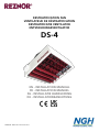
DESTRATIFICATION FAN
VENTILATEUR DE DÉSTRATIFICATION
DESTRATIFICATIE VENTILATOR
ENTSTAUBUNGSVENTILATOR
DS-4

These appliances meet the following UK directives
Electromagnetic Compatibility Regulations 2016
Electrical Equipment (Safety) Regulations 2016
Supply of Machinery (Safety) Regulations 2008
Supply of Machinery (Safety) Regulations (A) 2011
Ces appareils sont conformes aux directives CE suivantes
Deze toestellen voldoen aan de volgende EG-richtlijnen
Diese Geräte entsprechen den folgenden EG-Richtlinien
DIR 2014/30/EU:EMC
DIR 2014/35/EU:LVD
DIR 2006/42/EC:MD

Contents / Contenu / Inhoud / Inhalt
English (EN)
General Information ...................................4
Parts list ......................................................5
Technical information .................................. 6
Dimensions .................................................6
Wiring diagram .......................................... 8
Francais (FR)
Informations générales ...............................10
Liste des pièces ...........................................11
Informations techniques ..............................12
Dimensions .................................................12
Schéma de câblage ....................................14
Nederlands (NL)
Algemene informatie .................................16
Onderdelenlijst ............................................ 17
Technische informatie .................................18
Afmetingen ................................................18
Bedradingsschema .....................................20
Deutschland (DE)
Allgemeine Informationen ..........................22
Teileliste ......................................................23
Technische Informationen ...........................24
Abmessungen ............................................. 24
Schaltplan .................................................. 26
Please read this document carefully before commencing installation, commissioning and/or servicing.
Leave it with the end user/site agent to be placed in their premises technical file after installation.
Veuillez lire attentivement ce document avant de commencer l'installation, la mise en service et/ou l'entretien.
Laissez-le à l'utilisateur final/agent de site pour qu'il soit placé dans le dossier technique de ses locaux après l'installation.
Lees dit document zorgvuldig door voordat u begint met de installatie, de inbedrijfstelling en/of het onderhoud.
Laat het na de installatie achter bij de eindgebruiker/locatievertegenwoordiger, zodat het in het technisch dossier van het bedrijf kan worden opgenomen.
Bitte lesen Sie dieses Dokument sorgfältig, bevor Sie mit der Installation, Inbetriebnahme und/oder Wartung beginnen.
Überlassen Sie es dem Endbenutzer/Bauleiter, um es nach der Installation in die technischen Unterlagen seines Betriebs aufzunehmen.
WARNING / AVERTISSEMENT / WAARSCHUWING / WARNUNG
Improper installation, adjustment, alteration, service or maintenance can cause property damage, injury or death.
All work must be carried out by appropriately qualified persons.
The manufacturer does not take any responsibility in the event of non-observance of the regulations concerning the connection of the apparatus causing a
dangerous operation possibly resulting in damage to the apparatus and/or environment in which the unit is installed.
Une installation, un réglage, une modification, un service ou une maintenance incorrects peuvent entraîner des dommages matériels, des blessures ou la
mort.
Tous les travaux doivent être effectués par des personnes dûment qualifiées.
Le fabricant n'assume aucune responsabilité en cas de non-respect des prescriptions relatives au raccordement de l'appareil provoquant une opération dan-
gereuse pouvant entraîner des dommages à l'appareil et/ou à l'environnement dans lequel l'unité est installée.
Onjuiste installatie, afstelling, wijziging, service of onderhoud kan materiële schade, letsel of de dood tot gevolg hebben.
Alle werkzaamheden moeten worden uitgevoerd door gekwalificeerde personen.
De fabrikant neemt geen enkele verantwoordelijkheid in geval van niet-naleving van de voorschriften betreffende de aansluiting van het apparaat, waardoor
een gevaarlijke handeling ontstaat die mogelijk schade aan het apparaat en/of de omgeving waarin het apparaat is geïnstalleerd tot gevolg kan hebben.
Unsachgemäße Installation, Einstellung, Änderung, Wartung oder Instandhaltung kann zu Sachschäden, Verletzungen oder Tod führen.
Alle Arbeiten müssen von entsprechend qualifizierten Personen durchgeführt werden.
Der Hersteller übernimmt keine Verantwortung für den Fall, dass die Nichtbeachtung der Vorschriften für den Anschluss des Geräts zu einem gefährlichen
Betrieb führt, der möglicherweise Schäden am Gerät und/oder an der Umgebung, in der das Gerät installiert ist, verursacht

Page No 4 of 28 Reznor, DS-4, Installation Manual, EN 2022-10, D301232 Iss 1
EN General information
Reznor de-stratification fans are a self
contained unit incorporating an adjustable
four way louvre discharge, a high efficiency
axial fan and an integral pre-wired thermostat
mounted on the side of the unit.
Care should be taken to ensure that the
unit is not sited in areas where it would be
undesirable to recirculate high level air because
of fumes, etc., or where corrosive atmospheres
may attack the fan unit.
To obtain maximum benefit, de-stratification
fans should be sited in the higher part of the
building, close to the apex, approximately one
metre below the peak.
Fans located over heat generating machinery
or lighting maximise the benefits of ‘free heat’
whilst fans positioned close to doorways help
to quickly restore comfortable conditions after
door operation.
Fans should not be sited adjacent to large
expanses of wall or roof glazing, or in
close proximity to open flued heater units,
as the airflow could adversely affect flue
performance.
The de-stratification fan is equipped with four
eyebolt suspension points, one on each corner,
and may be suspended from these using
chains or wires.
Each de-stratification fan is equipped with a
cable gland mains input positioned on the
terminal box on top of the main fan.
Each unit will require a 230V 50Hz 1ph fused
supply to operate.
For safety and maintenance purposes, each
fan should be fitted with an isolator located
adjacent to the unit.
The information contained in this technical
manual is designed to aid a qualified or
competent service technician in the instruction
it is intended for.
Any reference made to Laws, Standards,
Directives, Codes of Practice or other
recommendations governing the application
and installation of heating appliances and
which may be referred to in Brochures,
Specifications, Quotations, and Installation,
Operation and Maintenance manuals is done
so for information and guidance purposes only
and should only be considered valid at the
time of the publication.
The Manufacturer cannot be held responsible
from any matters arising from the revision
to or introduction of new Laws, Standards,
Directives, Codes of Practice or other
recommendations.
Tools required
The following tools and equipment will be
required to complete this task:
1. Lengths of chain or suspension wire,
accessories, and relevant tools.
2. Length of 3 core 1.0mm² cable.
3. Wire strippers/cutters.
4. Electrical screwdriver.
5. Multi-meter.
Caution heavy item
The de-stratification fan is equipped with four
suspension points, one on each corner. These
take the form of an eyebolt. Using either
chain or wire rope, connect each point to a
rigid construction i.e. Unistrut, girders etc.
Note: Ensure the framework is adequate
to take the weight of the particular de-
stratification unit.
Once the de-stratification fan is in position, the
wiring can commence.

Reznor, DS-4, Installation Manual, EN 2022-10, D301232 Iss 1 Page No 5 of 28
EN
The de-stratification fan is despatched in a
cardboard box.
• Remove component from box.
• Adjust all outlet louvres to achieve desired
air distribution and ensure blades are not
resonating.
• Turn the power/spur on. The de-
stratification fan will now operate and
automatically switch off when the set
temperature has been reached.
• To check operation of the DS type unit,
rotate room thermostat dial to minimum
setting - fan should operate. Rotate room
thermostat dial to maximum setting - the
fan should turn off.
• Finally turn the room thermostat to
approximately 2° to 3° above the desired
room temperature. If the fan does not
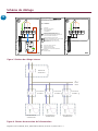
operate in this order, check wiring details in
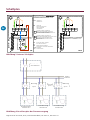
figure 4.
The unit is now ready for operation.
The information contained in this technical
manual is designed to aid a qualified or
competent service technician.
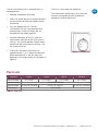
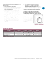
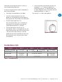
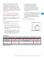
Product DS3-4 DS4-4 DS6-4 DS10-4
Fan assembly 01-27092 01-27093 01-27096 01-27094
Louvre spring 03-401EU-195046
Louvre blade 03-401US-201830 03-401US-196233 03-401US-1024920
Thermostat 28-16-029
Table 1 Parts list
Parts List
Figure 1 Thermostat

Page No 6 of 28 Reznor, DS-4, Installation Manual, EN 2022-10, D301232 Iss 1
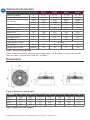
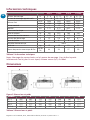
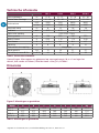
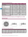
EN Technical information
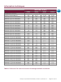
DS3-4 DS4-4 DS6-4 DS10-4
Mounting Height m 4 - 8 6 - 12 10 - 18 10 - 18
Approx Mounting Centres m 13 - 16 15 - 20 16 - 21 17 - 23
Air Volume m³/h 3000 5300 6600 9000
c.f.m 1765 3199 3885 5297
Maximum Throw m 8 12 18 18
Velocity m/s 3.77 4.72 6.53 5.73
Electrical Supply 230V 50Hz 1Phase
Motor Size W 108 250 380 520
Operating Current A 0.52 1.15 1.75 2.40
Starting Current A 1.5 2.4 6.0 6.7
Fuse Rating A 6 6 6 10
Thermostatic Control Included
Net Weight kg 15 19 21 27
Sound Pressure Level Lp db (A) 44 54 57 59
Table 2 Technical information
Notes: Mounting centres based on mounting height. (i.e. the lower the unit, the further
they are apart.) Sound level r=5m,Q=1,A=160m²
Dimensions
Figure 2 dimensions and weights
Model A B C D E F Kg
DS3-4 492 492 332 332 306 180 13.5
DS4-4 573 573 365 365 345 180 17.0
DS6-4 573 573 400 400 306 180 17.5
DS10-4 694 694 440 440 345 180 25.5
Table 3 dimensions and weights

Reznor, DS-4, Installation Manual, EN 2022-10, D301232 Iss 1 Page No 7 of 28
EN
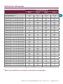
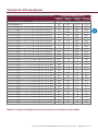
Technical information
Air Velocity (m/s)
DS3-4 DS4-4 DS6-4 DS10-4
Ambient temperature 21.0
Mounting Height (m) 4-8 6-12 10-18 10-18
Velocity at 4.0m from fan 2.9 N/A N/A N/A
Velocity at 4.5m from fan 2.6 N/A N/A N/A
Velocity at 5.0m from fan 2.4 N/A N/A N/A
Velocity at 5.5m from fan 2.2 N/A N/A N/A
Velocity at 6.0m from fan 2.0 3.1 N/A N/A
Velocity at 6.5m from fan 1.8 2.9 N/A N/A
Velocity at 7.0m from fan 1.7 2.7 N/A N/A
Velocity at 7.5m from fan 1.5 2.5 N/A N/A
Velocity at 8.0m from fan 1.4 2.4 N/A N/A
Velocity at 8.5m from fan N/A 2.3 N/A N/A
Velocity at 9.0m from fan N/A 2.2 N/A N/A
Velocity at 9.5m from fan N/A 2.0 N/A N/A
Velocity at 10.0m from fan N/A 1.9 3.3 3.9
Velocity at 10.5m from fan N/A 1.8 3.2 3.8
Velocity at 11.0m from fan N/A 1.7 3.1 3.7
Velocity at 11.5m from fan N/A 1.6 3.1 3.5
Velocity at 12.0m from fan N/A 1.5 3.0 3.3
Velocity at 12.5m from fan N/A N/A 2.8 3.1
Velocity at 13.0m from fan N/A N/A 2.6 2.9
Velocity at 13.5m from fan N/A N/A 2.5 2.8
Velocity at 14.0m from fan N/A N/A 2.3 2.6
Velocity at 14.5m from fan N/A N/A 2.2 2.4
Velocity at 15.0m from fan N/A N/A 2.1 2.3
Velocity at 15.5m from fan N/A N/A 2.0 2.2
Velocity at 16.0m from fan N/A N/A 1.9 2.0
Velocity at 16.5m from fan N/A N/A 1.6 1.9
Velocity at 17.0m from fan N/A N/A 1.4 1.8
Velocity at 17.5m from fan N/A N/A 1.2 1.5
Velocity at 18.0m from fan N/A N/A 0.9 1.2
Table 4 Air velocity between maximum and minimum mounting heights

Page No 8 of 28 Reznor, DS-4, Installation Manual, EN 2022-10, D301232 Iss 1
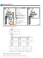
EN Wiring diagram
Figure 4 Power supply connection diagram
MM
N 1 C L
1
4
TH
230V 1N ~ 50Hz
NL
TH THERMOSTAT
THERMOSTAAT
MFAN MOTOR
MOTEUR DU VENTILATEUR
VENTILATORMOTOR
LÜFTERMOTOR
CONTROL TERMINALS THERMOSTAT
BORNES DE RACCORDEMENT THERMOSTAT
ELEKTRISCHE AANSLUITKLEMMEN THERMOSTAAT
ANSCHLUSSKLEMMEN THERMOSTAT
CONTROL TERMINALS FOR INSTALLER
BORNES DE RACCORDEMENT POUR L'INSTALLATEUR
ELEKTRISCHE AANSLUITKLEMMEN VOOR
INSTALLATEUR
ANSCHLUSSKLEMMEN FUR INSTALLATEUR
BK BLACK, NOIR, ZWART, SCHWARZ
BLUE, BLEU, BLAUW, BLAU
BROWN, BRUN, BRUIN, BRAUN
GREEN/YELLOW, VERT/JAUNE, GROEN/GEEL,
GRÜN/GELB
BL
BR
GN/Y
OR ORANGE, ORANJE
GN/Y
BK
BR
OR
BR
BL
MM
N 1 C L
230V 1N ~ 50Hz
NL
GN/Y
BK
BR
OR
DS DS-F
INSTALLER CONNECTIONS
CONNECTIONS A LA CHARGE DE L'INSTALLATEUR
AANSLUITINGEN DOOR INSTALLATEUR TE VOORZIEN
ELEKTROANSCHLUSS FUR INSTALLATEUR
Figure 3 Internal wiring diagram
Fused
Isolator
Fused
Isolator
Fused
Isolator
Distribution Board
Other
units
Destrat Fan #2 Destrat Fan #3
Destrat Fan #1

Reznor, DS-4, Installation Manual, EN 2022-10, D301232 Iss 1 Page No 9 of 28
EN
Notes

Page No 10 of 28 Reznor, DS-4, Manuel d'installation, FR 2022-10, D301232 Iss 1
FR
Information générales
Les ventilateurs de déstratification Gaz Industrie
sont une unité autonome incorporant une
décharge par déflecteur ajustable à quatre voies,
un ventilateur axial à haute efficacité et un
thermostat intégré pré-câblé monté sur le côté de
l’unité.
Veillez à ce que l’unité ne soit pas installée dans
des zones où il serait indésirable de faire recirculer
de l’air à haute altitude en raison de vapeurs,
etc., ou où des atmosphères corrosives pourraient
attaquer le ventilateur.
Pour obtenir un bénéfice maximal, les ventilateurs
de déstratification doivent être installés dans la
partie supérieure du bâtiment, près du sommet, à
environ un mètre sous le pic.
Les ventilateurs situés au-dessus de machines ou
d’éclairage générant de la chaleur maximisent les
avantages de la «chaleur libre», tandis que les
ventilateurs positionnés à proximité des portes
aident à rétablir rapidement des conditions
confortables après leur utilisation.
Les ventilateurs ne doivent pas être placés à
proximité de grandes surfaces vitrées de murs ou
de toits, ni à proximité de blocs de chauffage à
fluide ouverts, car le flux d’air pourrait nuire aux
performances du conduit de cheminée.
Le ventilateur de déstratification est équipé de
quatre points de suspension à œil, un à chaque
coin, et peut être suspendu à l’aide de chaînes ou
de fils.
Chaque ventilateur de déstratification est équipé
d’une entrée secteur pour presse-étoupe placée sur
la boîte à bornes au-dessus du ventilateur principal.
Chaque unité nécessitera une alimentation avec
fusible 230V 50Hz 1ph pour fonctionner.
Pour des raisons de sécurité et d’entretien, chaque
ventilateur doit être équipé d’un isolateur adjacent
à l’unité.
Toute référence à des lois, normes, directives,
codes de pratique ou autres recommandations
régissant l’application et l’installation d’appareils
de chauffage et pouvant être consultée dans
les manuels Brochure, Spécifications, Devis, et
Installation, utilisation et maintenance est faite à
titre informatif et informatif. uniquement à des fins
d’orientation et ne devrait être considéré comme
valide qu’au moment de la publication.
Le fabricant ne peut être tenu responsable
des problèmes découlant de la révision ou de
l’introduction de nouvelles lois, normes, directives,
codes de pratique ou autres recommandations.
Les informations contenues dans ce manuel
technique sont conçues pour aider un technicien
de maintenance qualifié ou compétent dans
l’instruction à laquelle il est destiné.Longueurs de
chaînes ou câbles de suspension, accessoires et
outils associés.
Outils nécessaires
Les outils et équipements suivants seront
nécessaires pour mener à bien cette tâche:
1. Longueurs de fil de chaîne ou de
suspension, accessoires et outils pertinents.
2. Longueur du câble 3 conducteurs 1.0mm².
3. Pinces à dénuder / cutters.
4. Tournevis électrique.
5. Multi-mètre.
Attention - Objet Lourd!
Reliez chaque point de suspension à une
construction rigide, à savoir Unistrut, des poutres,
etc.
Remarque: Assurez-vous que le cadre est
adéquat pour prendre le poids de l’unité
de détratification particulière.
Une fois le ventilateur de déstratification en place,
le câblage peut commencer.

Reznor, DS-4, Manuel d'installation, FR 2022-10, D301232 Iss 1 Page No 11 of 28
FR
L’éventail de déstratification est expédié dans une
boîte en carton.
• Retirer le composant de la boîte.
• Ajustez toutes les grilles de sortie pour obtenir
la distribution d’air souhaitée et pour que les
lames ne résonnent pas.
• Allumez l’alimentation. Le ventilateur de
déstratification va maintenant fonctionner
et s’éteindre automatiquement lorsque la
température définie est atteinte.
• Pour vérifier le fonctionnement de l’unité de
type DS, tournez le cadran du thermostat
d’ambiance sur le réglage minimum - le
ventilateur devrait fonctionner. Tournez
le cadran du thermostat d’ambiance sur
le réglage maximum - le ventilateur doit
s’éteindre.
• Enfin, réglez le thermostat d’ambiance
à environ 4° à 5° au-dessus de la valeur
souhaitée.température ambiante. Si le
ventilateur ne fonctionne pas dans cet ordre,
vérifiez les détails de câblage dans la figure 4.
L’unité est maintenant prête à fonctionner.
Le fabricant ne peut être tenu responsable
des problèmes découlant de la révision ou de
l’introduction de nouvelles lois, normes, directives,
codes de pratique ou autres
recommandations.
Les informations contenues
dans ce manuel technique
sont conçues pour aider
un technicien qualifié ou
compétent.
Produit DS3-4 DS4-4 DS6-4 DS10-4
Assemblage de ventilateur 01-27092 01-27093 01-27096 01-27094
Printemps du Louvre 03-401EU-195046
Lame du louvre 03-401US-201830 03-401US-196233 03-401US-1024920
Thermostat 28-16-029
Tableau 1 Liste des pièces
Liste des pièces
Figure 1 Thermostat

Page No 12 of 28 Reznor, DS-4, Manuel d'installation, FR 2022-10, D301232 Iss 1
FR
Information techniques
DS3-4 DS4-4 DS6-4 DS10-4
Hauteur de montage m 4 - 8 6 - 12 10 - 18 10 - 18
Centres de montage approximatifs m 13 - 16 15 - 20 16 - 21 17 - 23
Volume d’air m³/h 3000 5300 6600 9000
c.f.m 1765 3199 3885 5297
Lancer maximal m 8 12 18 18
Rapidité m/s 3.77 4.72 6.53 5.73
Fourniture électrique 230V 50Hz 1Phase
Taille du moteur W 108 250 380 520
Courant de fonctionnement A 0.52 1.15 1.75 2.40
Courant de démarrage A 1.5 2.4 6.0 6.7
Note de fusible A 6 6 6 10
Contrôle thermostatique Inclus
Poids net kg 15 19 21 27
Niveau de pression acoustique @ 5m Lp db
(A) 44 54 57 59
Tableau 2 Information techniques
Notes: Montage des centres basés sur la hauteur de montage. (c’est à dire la partie
inférieure de l’unité, plus ils sont à part). Niveau sonore Q=2, A=160m²
Dimensions
Figure 2 Dimensions et poids
Modèle A B C D E F Kg
DS3-4 492 492 332 332 306 180 13.5
DS4-4 573 573 365 365 345 180 17.0
DS6-4 573 573 400 400 306 180 17.5
DS10-4 694 694 440 440 345 180 25.5
Tableau 3 Dimensions et poids

Reznor, DS-4, Manuel d'installation, FR 2022-10, D301232 Iss 1 Page No 13 of 28
FR
Information techniques
Vélocité de l’air (m/s)
DS3-4 DS4-4 DS6-4 DS10-4
Température ambiante 21.0
Hauteur de montage (m) 4-8 6-12 10-18 10-18
Vélocité à 4.0m du ventilateur 2.9 N/A N/A N/A
Vélocité à 4.5m du ventilateur 2.6 N/A N/A N/A
Vélocité à 5.0m du ventilateur 2.4 N/A N/A N/A
Vélocité à 5.5m du ventilateur 2.2 N/A N/A N/A
Vélocité à 6.0m du ventilateur 2.0 3.1 N/A N/A
Vélocité à 6.5m du ventilateur 1.8 2.9 N/A N/A
Vélocité à 7.0m du ventilateur 1.7 2.7 N/A N/A
Vélocité à 7.5m du ventilateur 1.5 2.5 N/A N/A
Vélocité à 8.0m du ventilateur 1.4 2.4 N/A N/A
Vélocité à 8.5m du ventilateur N/A 2.3 N/A N/A
Vélocité à 9.0m du ventilateur N/A 2.2 N/A N/A
Vélocité à 9.5m du ventilateur N/A 2.0 N/A N/A
Vélocité à 10.0m du ventilateur N/A 1.9 3.3 3.9
Vélocité à 10.5m du ventilateur N/A 1.8 3.2 3.8
Vélocité à 11.0m du ventilateur N/A 1.7 3.1 3.7
Vélocité à 11.5m du ventilateur N/A 1.6 3.1 3.5
Vélocité à 12.0m du ventilateur N/A 1.5 3.0 3.3
Vélocité à 12.5m du ventilateur N/A N/A 2.8 3.1
Vélocité à 13.0m du ventilateur N/A N/A 2.6 2.9
Vélocité à 13.5m du ventilateur N/A N/A 2.5 2.8
Vélocité à 14.0m du ventilateur N/A N/A 2.3 2.6
Vélocité à 14.5m du ventilateur N/A N/A 2.2 2.4
Vélocité à 15.0m du ventilateur N/A N/A 2.1 2.3
Vélocité à 15.5m du ventilateur N/A N/A 2.0 2.2
Vélocité à 16.0m du ventilateur N/A N/A 1.9 2.0
Vélocité à 16.5m du ventilateur N/A N/A 1.6 1.9
Vélocité à 17.0m du ventilateur N/A N/A 1.4 1.8
Vélocité à 17.5m du ventilateur N/A N/A 1.2 1.5
Vélocité à 18.0m du ventilateur N/A N/A 0.9 1.2
Tableau 4 Vitesse de l’air entre les hauteurs de montage maximale et minimale

Page No 14 of 28 Reznor, DS-4, Manuel d'installation, FR 2022-10, D301232 Iss 1
FR
Schéma de câblage
Figure 4 Schéma de connexion de l’alimentation
MM
N 1 C L
1
4
TH
230V 1N ~ 50Hz
NL
TH THERMOSTAT
THERMOSTAAT
MFAN MOTOR
MOTEUR DU VENTILATEUR
VENTILATORMOTOR
LÜFTERMOTOR
CONTROL TERMINALS THERMOSTAT
BORNES DE RACCORDEMENT THERMOSTAT
ELEKTRISCHE AANSLUITKLEMMEN THERMOSTAAT
ANSCHLUSSKLEMMEN THERMOSTAT
CONTROL TERMINALS FOR INSTALLER
BORNES DE RACCORDEMENT POUR L'INSTALLATEUR
ELEKTRISCHE AANSLUITKLEMMEN VOOR
INSTALLATEUR
ANSCHLUSSKLEMMEN FUR INSTALLATEUR
BK BLACK, NOIR, ZWART, SCHWARZ
BLUE, BLEU, BLAUW, BLAU
BROWN, BRUN, BRUIN, BRAUN
GREEN/YELLOW, VERT/JAUNE, GROEN/GEEL,
GRÜN/GELB
BL
BR
GN/Y
OR ORANGE, ORANJE
GN/Y
BK
BR
OR
BR
BL
MM
N 1 C L
230V 1N ~ 50Hz
NL
GN/Y
BK
BR
OR
DS DS-F
INSTALLER CONNECTIONS
CONNECTIONS A LA CHARGE DE L'INSTALLATEUR
AANSLUITINGEN DOOR INSTALLATEUR TE VOORZIEN
ELEKTROANSCHLUSS FUR INSTALLATEUR
Figure 3 Schéma de câblage interne
Sectionneur
à fusibles
Sectionneur
à fusibles
Sectionneur
à fusibles
Tableau de
distribution
autres
unités
Déstratification
ventilateur # 2
Déstratification
ventilateur # 3
Déstratification
ventilateur # 1

Reznor, DS-4, Manuel d'installation, FR 2022-10, D301232 Iss 1 Page No 15 of 28
FR
Remarques

Page No 16 of 28 Reznor, DS-4, Installatiehandleiding, NL 2022-10, D301232 Iss 1
NL
Algemene informatie
De destratificatieventilatoren van Reznor
zijneen op zichzelf staande eenheid met
instelbare vierwegroosterafvoer, een axiale
ventilator met hoog rendement en een
geïntegreerde voorbedrade thermostaat aan
de zijkant van de eenheid.
Zorg ervoor dat de unit niet wordt geplaatst
op plaatsen waar het ongewenst is om lucht
op hoog niveau te recirculeren vanwege
dampen, enz., Of waar corrosieve atmosferen
de ventilatoreenheid kunnen aantasten.
Om maximaal voordeel te behalen, moeten
destratificatieventilatoren in het hogere deel
van het gebouw worden geplaatst, dicht bij de
top, ongeveer een meter onder de piek.
Ventilatoren boven warmtegenererende
machines of verlichting maximaliseren
de voordelen van ‘gratis warmte’, terwijl
ventilatoren die dicht bij deuropeningen
zijn geplaatst helpen om snel comfortabele
omstandigheden te herstellen na de werking
van de deur.
Ventilatoren mogen niet worden geplaatst
naast grote vlakken van muur- of
dakbeglazing, of in de buurt van open
verwarmingen, omdat de luchtstroom de
prestaties van het rookkanaal nadelig kan
beïnvloeden.
De destratificatieventilator is uitgerust met vier
oogboutophangpunten, één op elke hoek,
en kan aan deze worden opgehangen met
kettingen of draden.
Elke destratificatieventilator is uitgerust
met een kabeldoorvoer op de klemmenkast
bovenop de hoofdventilator.
Elke eenheid heeft een 230V 50Hz
1ph gezekerde voeding nodig om te
kunnen werken. Voor veiligheids- en
onderhoudsdoeleinden moet elke ventilator
worden voorzien van een isolator naast de
eenheid.
De informatie in deze technische handleiding
is bedoeld om een gekwalificeerde of
bevoegde onderhoudstechnicus te helpen bij
de instructie waarvoor zij bestemd is.
Elke verwijzing naar wetten, normen,
richtlijnen, praktijkcodes of andere
aanbevelingen voor de toepassing en installatie
van verwarmingstoestellen en waarnaar kan
worden verwezen in brochures, specificaties,
offertes en installatie-, bedienings- en
onderhoudshandleidingen wordt gedaan
ter informatie en alleen als leidraad en dient
alleen als geldig te worden beschouwd op het
moment van publicatie.
De fabrikant kan niet aansprakelijk worden
gesteld voor zaken die voortvloeien uit de
herziening of invoering van nieuwe wetten,
normen, richtlijnen, praktijkcodes of andere
aanbevelingen.
Vereist gereedschap
De volgende gereedschappen en apparatuur
zijn vereist om deze taak te voltooien:
1. Lengtes van ketting of ophangdraad,
accessoires en relevant gereedschap.
2. Lengte van 3-aderige 1,0 mm² kabel.
3. Draadstrippers / -snijders.
4. Elektrische schroevendraaier.
5. Multi-meter.
Let op zwaar voorwerp
De ontstratingsventilator is voorzien van
vier ophangpunten, één op elke hoek.
Deze hebben de vorm van een oogbout.
Gebruik een ketting of staalkabel om elk
punt te verbinden met een stijve constructie,
bijvoorbeeld Unistrut, liggers enz.
Opmerking: Zorg ervoor dat het
raamwerk het gewicht van de specifieke
ontstratingsventilator kan dragen.

Reznor, DS-4, Installatiehandleiding, NL 2022-10, D301232 Iss 1 Page No 17 of 28
NL
Zodra de ontstratingsventilator in positie is,
kan de bedrading beginnen.
De ontstratingsventilator wordt verzonden in
een kartonnen doos.
• Verwijder het onderdeel uit de doos.
• Stel alle uitblaaslamellen af om de
gewenste luchtverdeling te verkrijgen en
zorg ervoor dat de lamellen niet resoneren.
• Zet de stroom/spoel aan. De
ontstratingsventilator zal nu werken en
automatisch uitschakelen wanneer de
ingestelde temperatuur is bereikt.
• Om de werking van de DS-unit te
controleren, draait u de regelknop van de
kamerthermostaat naar de minimumstand
- de ventilator moet werken. Draai de
regelknop van de kamerthermostaat naar
de maximale stand - de ventilator moet
uitschakelen.
• Draai tenslotte de kamerthermostaat tot
ongeveer 2° à 3° boven de gewenste
kamertemperatuur. Als de ventilator niet
in deze volgorde werkt, controleer dan de
bedradingsdetails in figuur 4.
Het toestel is nu klaar voor gebruik.
Product DS3-4 DS4-4 DS6-4 DS10-4
Ventilator montage 01-27092 01-27093 01-27096 01-27094
Louvre lente 03-401EU-195046
Louvre blad 03-401US-
201830
03-401US-196233 03-401US-
1024920
Thermostaat 28-16-029
Tabel 1 Onderdelenlijst
Onderdelen lijst
Figuur 1 Thermostaat

Page No 18 of 28 Reznor, DS-4, Installatiehandleiding, NL 2022-10, D301232 Iss 1
NL
Technische informatie
DS3-4 DS4-4 DS6-4 DS10-4
Montagehoogte m 4 - 8 6 - 12 10 - 18 10 - 18
Centra voor montage m 13 - 16 15 - 20 16 - 21 17 - 23
Luchtvolume m³/h 3000 5300 6600 9000
c.f.m 1765 3199 3885 5297
Maximale worp m 8 12 18 18
Snelheid m/s 3.77 4.72 6.53 5.73
Elektrische voeding 230V 50Hz 1 Fase
Motor grootte W 108 250 380 520
Bedrijfsstroom A 0.52 1.15 1.75 2.40
Startstroom A 1.5 2.4 6.0 6.7
Zekering A 6 6 6 10
Thermostatische regeling Inbegrepen
Netto gewicht kg 15 19 21 27
Geluidsdrukniveau @ 5m Lp db (A) 44 54 57 59
Tabel 2 Technische informatie
Opmerkingen: Montagecentra gebaseerd op montagehoogte. (d.w.z. hoe lager het
toestel, hoe verder uit elkaar.) Geluidsniveau r=5m,Q=1,A=160m²
Dimensies
Figuur 2 Afmetingen en gewichten
Model A B C D E F Kg
DS3-4 492 492 332 332 306 180 13.5
DS4-4 573 573 365 365 345 180 17.0
DS6-4 573 573 400 400 306 180 17.5
DS10-4 694 694 440 440 345 180 25.5
Tabel 3 Afmetingen en gewichten

Reznor, DS-4, Installatiehandleiding, NL 2022-10, D301232 Iss 1 Page No 19 of 28
NL
Technische informatie
Luchtsnelheid (m/s)
DS3-4 DS4-4 DS6-4 DS10-4
Omgevingstemperatuur 21.0
Montagehoogte (m) 4-8 6-12 10-18 10-18
Snelheid bij 4.0m van de ventilator 2.9 N/A N/A N/A
Snelheid bij 4.5m van de ventilator 2.6 N/A N/A N/A
Snelheid bij 5.0m van de ventilator 2.4 N/A N/A N/A
Snelheid bij 5.5m van de ventilator 2.2 N/A N/A N/A
Snelheid bij 6.0m van de ventilator 2.0 3.1 N/A N/A
Snelheid bij 6.5m van de ventilator 1.8 2.9 N/A N/A
Snelheid bij 7.0m van de ventilator 1.7 2.7 N/A N/A
Snelheid bij 7.5m van de ventilator 1.5 2.5 N/A N/A
Snelheid bij 8.0m van de ventilator 1.4 2.4 N/A N/A
Snelheid bij 8.5m van de ventilator N/A 2.3 N/A N/A
Snelheid bij 9.0m van de ventilator N/A 2.2 N/A N/A
Snelheid bij 9.5m van de ventilator N/A 2.0 N/A N/A
Snelheid bij 10.0m van de ventilator N/A 1.9 3.3 3.9
Snelheid bij 10.5m van de ventilator N/A 1.8 3.2 3.8
Snelheid bij 11.0m van de ventilator N/A 1.7 3.1 3.7
Snelheid bij 11.5m van de ventilator N/A 1.6 3.1 3.5
Snelheid bij 12.0m van de ventilator N/A 1.5 3.0 3.3
Snelheid bij 12.5m van de ventilator N/A N/A 2.8 3.1
Snelheid bij 13.0m van de ventilator N/A N/A 2.6 2.9
Snelheid bij 13.5m van de ventilator N/A N/A 2.5 2.8
Snelheid bij 14.0m van de ventilator N/A N/A 2.3 2.6
Snelheid bij 14.5m van de ventilator N/A N/A 2.2 2.4
Snelheid bij 15.0m van de ventilator N/A N/A 2.1 2.3
Snelheid bij 15.5m van de ventilator N/A N/A 2.0 2.2
Snelheid bij 16.0m van de ventilator N/A N/A 1.9 2.0
Snelheid bij 16.5m van de ventilator N/A N/A 1.6 1.9
Snelheid bij 17.0m van de ventilator N/A N/A 1.4 1.8
Snelheid bij 17.5m van de ventilator N/A N/A 1.2 1.5
Snelheid bij 18.0m van de ventilator N/A N/A 0.9 1.2
Tabel 4 Luchtsnelheid tussen maximale en minimale montagehoogte

Page No 20 of 28 Reznor, DS-4, Installatiehandleiding, NL 2022-10, D301232 Iss 1
NL
Bedradingsschema
Figuur 4 Aansluitschema van de voeding
MM
N 1 C L
1
4
TH
230V 1N ~ 50Hz
NL
TH THERMOSTAT
THERMOSTAAT
MFAN MOTOR
MOTEUR DU VENTILATEUR
VENTILATORMOTOR
LÜFTERMOTOR
CONTROL TERMINALS THERMOSTAT
BORNES DE RACCORDEMENT THERMOSTAT
ELEKTRISCHE AANSLUITKLEMMEN THERMOSTAAT
ANSCHLUSSKLEMMEN THERMOSTAT
CONTROL TERMINALS FOR INSTALLER
BORNES DE RACCORDEMENT POUR L'INSTALLATEUR
ELEKTRISCHE AANSLUITKLEMMEN VOOR
INSTALLATEUR
ANSCHLUSSKLEMMEN FUR INSTALLATEUR
BK BLACK, NOIR, ZWART, SCHWARZ
BLUE, BLEU, BLAUW, BLAU
BROWN, BRUN, BRUIN, BRAUN
GREEN/YELLOW, VERT/JAUNE, GROEN/GEEL,
GRÜN/GELB
BL
BR
GN/Y
OR ORANGE, ORANJE
GN/Y
BK
BR
OR
BR
BL
MM
N 1 C L
230V 1N ~ 50Hz
NL
GN/Y
BK
BR
OR
DS DS-F
INSTALLER CONNECTIONS
CONNECTIONS A LA CHARGE DE L'INSTALLATEUR
AANSLUITINGEN DOOR INSTALLATEUR TE VOORZIEN
ELEKTROANSCHLUSS FUR INSTALLATEUR
Figuur 3 intern bedradingsschema
Zekering
uitloper
Zekering
uitloper
Zekering
uitloper
Distributiebord
Andere
ennheden
Destratificatie Fan #2 Destratificatie Fan #3
Destratificatie Fan #1
Seite wird geladen ...
Seite wird geladen ...
Seite wird geladen ...
Seite wird geladen ...
Seite wird geladen ...
Seite wird geladen ...
Seite wird geladen ...
Seite wird geladen ...
-
 1
1
-
 2
2
-
 3
3
-
 4
4
-
 5
5
-
 6
6
-
 7
7
-
 8
8
-
 9
9
-
 10
10
-
 11
11
-
 12
12
-
 13
13
-
 14
14
-
 15
15
-
 16
16
-
 17
17
-
 18
18
-
 19
19
-
 20
20
-
 21
21
-
 22
22
-
 23
23
-
 24
24
-
 25
25
-
 26
26
-
 27
27
-
 28
28


in anderen Sprachen
- English: Reznor DS-4 Installation guide
- français: Reznor DS-4 Guide d'installation
- Nederlands: Reznor DS-4 Installatie gids
Andere Dokumente
-
Nortek REZNOR DS10-4 Installationsanleitung
-
EUROPA 4415142 Benutzerhandbuch
-
Europlast EE125TA Benutzerhandbuch
-
Steinberg VST Instruments Hypersonic 2 Benutzerhandbuch
-
Korg PADKONTROL Benutzerhandbuch
-
Mark MDV Blue 311 Technical Manual
-
Rancilio EGRO ONE Touch Pure Coffee Technical Manual
-
-
-