Seite wird geladen ...

SIMATIC NET
Kompaktbetriebsanleitung
Ausgabe 05/2019
Deutsch
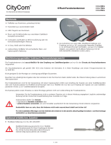
ANT795-6MP (Omni-Antenne 2,4 / 5 GHz)
Copyright © Siemens AG 2019 All rights reserved
Weitergabe sowie Vervielfältigung dieser Unterlage, Verwertung und
Mitteilung ihres Inhalts ist nicht gestattet, soweit nicht ausdrücklich zuge-
standen. Zuwiderhandlungen verpflichten zu Schadensersatz. Alle Rechte
vorbehalten, insbesondere für den Fall der Patenterteilung oder
GM-Eintragung.
Haftungsausschluss
Wir haben den Inhalt der Druckschrift auf Übereinstimmung mit der be-
schriebenen Hard- und Software geprüft. Dennoch können Abweichungen
nicht ausgeschlossen werden, so dass wir für die vollständige Überein-
stimmung keine Gewähr übernehmen. Die Angaben in dieser Druckschrift
werden regelmäßig überprüft und notwendige Korrekturen sind in den
nachfolgenden Auflagen enthalten.
Technische Änderungen bleiben vorbehalten.
Siemens AG
Digital Industries
Postfach 48 48
D-90026 NÜRNBERG
DEUTSCHLAND
Security-Hinweise
Um Anlagen, Systeme, Maschinen und Netzwerke gegen Cyber-
Bedrohungen zu sichern, ist es erforderlich, ein ganzheitliches Industrial
Security-Konzept zu implementieren (und kontinuierlich aufrechtzuerhal-
ten), das dem aktuellen Stand der Technik entspricht. Die Produkte und
Lösungen von Siemens formen nur einen Bestandteil eines solchen
Konzepts. Weitergehende Informationen über Industrial Security finden
Sie unter https://www.siemens.com/industrialsecurity.
Recycling und Entsorgung
Die Produkte sind schadstoffarm, recyclingfähig und erfüllen
die Anforderungen der WEEE-Richtlinie 2012/19/EU zur Ent-
sorgung von Elektro- und Elektronik-Altgeräten.
Entsorgen Sie die Produkte nicht bei öffentlichen Entsor-
gungsstellen.
Für ein umweltverträgliches Recycling und die Entsorgung Ihres Altgeräts
wenden Sie sich an einen zertifizierten Entsorgungsbetrieb für Elektronik-
schrott oder an Ihren Siemens-Ansprechpartner:
https://support.industry.siemens.com/cs/ww/de/view/109479891
Beachten Sie unterschiedliche länderspezifische Regelungen.
Warnhinweiskonzept
Dieses Handbuch enthält Hinweise, die Sie zu Ihrer persönlichen Sicher-
heit sowie zur Vermeidung von Sachschäden beachten müssen. Die
Hinweise zu Ihrer persönlichen Sicherheit sind durch ein Warndreieck
hervorgehoben, Hinweise zu alleinigen Sachschäden stehen ohne Warn-
dreieck. Je nach Gefährdungsstufe werden die Warnhinweise in abneh-
mender Reihenfolge wie folgt dargestellt.
GEFAHR
bedeutet, dass Tod oder schwere Körperverletzung eintreten wird, wenn
die entsprechenden Vorsichtsmaßnahmen nicht getroffen werden.
WARNUNG
bedeutet, dass Tod oder schwere Körperverletzung eintreten kann,
wenn die entsprechenden Vorsichtsmaßnahmen nicht getroffen werden.
VORSICHT
bedeutet, dass eine leichte Körperverletzung eintreten kann, wenn die
entsprechenden Vorsichtsmaßnahmen nicht getroffen werden.
ACHTUNG
bedeutet, dass Sachschaden eintreten kann, wenn die entsprechenden
Vorsichtsmaßnahmen nicht getroffen werden.
Qualifiziertes Personal
Das zu dieser Dokumentation zugehörige Produkt/System darf nur von für
die jeweilige Aufgabenstellung qualifiziertem Personal gehandhabt
werden unter Beachtung der für die jeweilige Aufgabenstellung zugehöri-
gen Dokumentation, insbesondere der darin enthaltenen Sicherheits- und
Warnhinweise. Qualifiziertes Personal ist auf Grund seiner Ausbildung
und Erfahrung befähigt, im Umgang mit diesen Produkten/ Systemen
Risiken zu erkennen und mögliche Gefährdungen zu vermeiden.
1 Sicherheitshinweise
WARNUNG
Lebensgefahr durch Blitzschlag
Antennen im Außenbereich müssen sich im Fangbereich eines Blitzab-
leiters befinden.
Stellen Sie sicher, dass für alle von außen eingeführten leitfähigen
Systeme die Möglichkeit eines Blitzschutz-Potenzialausgleichs besteht.
Beachten Sie bei der Umsetzung Ihres Blitzschutzkonzepts unbedingt
die Anforderungen der Normen VDE 0182 bzw. IEC 62305.
ACHTUNG
Unsachgemäße Verwendung
Das Gerät (und de
ssen Bauteile) darf nur entsprechend der im Katalog
oder der Betriebsanleitung beschriebenen Verwendung eingesetzt wer-
den. Kombinationen mit Geräten oder Komponenten anderer Hersteller
sind erlaubt, wenn diese durch Siemens freigegeben wurden.
Eine korrekte und sichere Funktion des Geräts ist nur dann sicherge-
stellt, wenn es entsprechend der Empfehlung transportiert, aufbewahrt,
aufgestellt, installiert, benutzt und gepflegt wird.
2 Lieferumfang
Folgende Teile gehören zum Lieferumfang der Antenne:
• 1x Antenne mit 1x N-Connector female
• Montagezubehör zur Befestigung der Antenne auf der Halterung
(1x Zahnscheibe, 1x Mutter)
• Montagezubehör zur Befestigung der Halter
ung
(
2x Bügel, 1x Halterung, 4x Unterlegscheiben, 4x Federringe,
4x Muttern)
• 1x Kompaktbetriebsanleitung
Überprüfen Sie die Vollständigkeit der Lieferung. Setzen Sie sich bei
unvollständiger Lieferung oder bei äußeren Beschädigungen mit Ihrem
Lieferanten oder der örtlichen Siemens-Geschäftsstelle in Verbindung.
3 Montage (Mastmontage)
Bei Montage und Demontage der Antennen-Verbindungsleitung oder der
Antenne auf der Halterung muss mit einem Gabelschlüssel (Schlüssel-
weite 30 mm) an der Sechskantschraube des Antennenfußes gegenge-
halten werden.
1. Entfernen Sie Öl und andere Verunreinigungen von den
Montageteilen.
2. Verschrauben Sie die Antenne mit der Zahnscheibe und der Mutter
auf der Halterung. Das Anzugsmoment der Mutter beträgt max.
12 Nm (Schlüsselweite 21 mm).
3. Verschrauben Sie die Bügel mit einer Unterlegscheibe , einem
Federring und einer Mutter an der Halterung .
4. Schrauben Sie die flexible Verbindungsleitung (nicht im Lieferumfang
ent
halten) an die Antenne. Das Anzugsmoment der Überwurfmutter:
1,35 Nm (min.) - 1,5 Nm (max.).
5. Schützen Sie die Anschlüsse vor Umwelteinflüssen (z. B. mit selbst-
vulkanisierendem Klebeband oder einem Schrumpfschlauch).
Bügel, Gewinde: 5/16'' -
18 UNC - 2A
Federring, Gewinde:
5
/
16
''
Sechskantmutter, Schlüsselweite:
1
/
2
'', Gewinde:
5
/
16
''- 18, Dicke
17
/
64
''
L-Halterung
Scheibe, Gewinde: 5/16''
C79000-8974-C407-05

4 Technische Daten
Betriebsfrequenz
2,4 ... 2,5 GHz
4,94 ... 5,925 GHz
Impedanz
50 Ω
Polarisation
Linear, vertikal
Abstrahlcharakteristik
Omnidirektional
Antennengewinn
- bei
2,4 - 2,5 GHz
- bei
4,94 - 5,925 GHz
5 dB
i
7 dBi
VSWR
< 2,0
Strahlw
inkel
- Horizontal
- V
ertikal
360°
25°
(bei 5 dBi)
15° (bei 7 dBi)
Anschluss/
Steckverbindung 1 N-Connector/female
Empfangsleistung max.
25 W
Material
- A
ußenhülle
- A
ntennenfuß
- B
ügel
- L-Halterung
K
unststoff, UV-beständig
Messing, verchromt
Stahl, dreiwertiges Nickel-Zink
Aluminium, harteloxiert
Umgebungstemperatur
- W
ährend Betrieb
- W
ährend Lagerung
- W
ährend Transport
-40 °C
... 80 °C
-40 °C ... 80 °C
-40 °C ... 80 °C
Schutzart IP
IP65/67
Windlast
19,6 N
Strömungsw
iderstand 0,0046 m²
Nettogewicht
140 g
Silikonfrei
Ja
Salzsprühnebeltest
Gemäß CEI IEC60068-2-52, Severity 1
5 Maßbild
Die Maße sind in mm angegeben.
M
astdurchmesser
6 Felddiagramme
Horizontal 2,48 GHz
V
ertikal 2,48 GHz
H
orizontal 5,6 GHz
V
ertikal 5,6 GHz

SIMATIC NET
Compact Operating Instructions
Release 05/2019
English
ANT795-6MP (omni antenna 2.4 / 5 GHz)
Copyright © Siemens AG 2019 All rights reserved
The reproduction, transmission or use of this document or its contents is
not permitted without express written authority. Offenders will be liable for
damages. All rights, including rights created by patent grant or registration
of a utility or design, are reserved.
Disclaimer of liability
We have checked the contents of this manual for agreement with the
hardware and software described. Since deviations cannot be preclud-ed
entirely, we cannot guarantee full agreement. However, the data in this
manual are reviewed regularly and any necessary corrections included in
subsequent editions.
Technical data subject to change without prior notice.
Siemens AG
Digital Industries
Postfach 48 48
D-90026 NÜRNBERG
GERMANY
Security information
In order to protect plants, systems, machines and networks against cyber
threats, it is necessary to implement – and continuously maintain – a
holistic, state-of-the-art industrial security concept. Siemens’ products and
solutions constitute one element of such a concept. For more information
about industrial security, please visit
https://www.siemens.com/industrialsecurity
Recycling and disposal
The products are low in pollutants, can be recycled and meet
the re-quirements of the WEEE directive 2012/19/EU for the
disposal of electrical and electronic equipment.
Do not dispose of the products at public disposal sites.
For environmentally friendly recycling and the disposal of your
old device contact a certified disposal company for electronic scrap or
your Siemens contact
https://support.industry.siemens.com/cs/ww/en/view/109479891.
Note the different national regulations.
Warning notice system
This manual contains notices you have to observe in order to ensure your
personal safety, as well as to prevent damage to property. The notices
referring to your personal safety are highlighted in the manual by a safety
alert symbol, notices referring only to property damage have no safety
alert symbol. These notices shown below are graded according to the
degree of danger.
DANGER
indicates that death or severe personal injury will result if proper precau-
tions are not taken.
WARNING
indicates that death or severe personal injury may result if proper pre-
cautions are not taken.
CAUTION
indicates that minor personal injury can result if proper precautions are
not taken.
NOTICE
indicates that property damage can result if proper precautions are not
taken.
Qualified Personnel
The product/system described in this documentation may be operated
only by personnel qualified for the specific task in accordance with the
relevant documentation, in particular its warning notices and safety
instructions. Qualified personnel are those who, based on their training
and experience, are capable of identifying risks and avoiding potential
hazards when working with these products/systems.
1 S
afety notes
WARNING
Danger due to lightning strikes
Antennas installed outdoors must be within the area covered by a light-
ning protection system.
Ma
ke sure that all conducting systems entering from outdoors can be
protected by a lightning protection potential equalization system.
When implementing your lightning protection concept, make sure you
adhere to the VDE 0182 or IEC 62305 standard.
NOTICE
Improper use
The device (and its components) may only be used for the application
described in the catalog or the operating instructions. Combinations with
devices or components of other manufacturers are permitted it they have
been approved by Siemens.
Correct and sa
fe operation of the device is guaranteed only when it is
transported, store
d, set up, installed, used and maintained according to
the recommendations.
2 Components of the product
The following components are supplied with the antenna:
• 1x antenna with 1x N Connector female
• Mounting material for securing the antenna to the mount
(1x toothed lock washer, 1x nut)
• Mounting material for securing the mount
(2x U-bolts, 1x L-bracket, 4x washers, 4x spring washers,
4x nuts)
• 1x Compact Operating Instructions
Please check that the consignment you have received is complete. If it is
not complete or there are signs of external damage, please contact your
supplier or your local Siemens office.
3 Mounting (mast mounting)
When mounting and removing the antenna connection cable or the an-
tenna on the mount, you have to hold the hexagon nut of the antenna foot
in place with an open-ended wrench (size 30 mm).
1. Remove any oil and other contamination from the mounting parts.
2. Screw the antenna with the toothed lock washer and the nut on the
m
ount. The tightening torque of the nut is max. 12 Nm. (wrench size
21 mm).
3. Screw the U-bolts with one washer , one spring washer and a
nut to the L-bracket .
4. Scr
ew the antenna connection cable (not included in the scope of
delivery) to the antenna. The tightening torque of the nut: 1.35 Nm
(min) – 1.5 Nm (max).
5. Protect the connectors from environmental influences (e.g. with self-
vulcanizing adhesive tape or a shrink-on sleeve).
U-bolt, Thread:
5
/
16
'' –
18 UNC - 2A
Spring washer, Thread:
5
/
16
''
Hexagon nut, wrench size:
1
/
2
'',
Thread:
5
/
16
''- 18, thickness
17
/
64
''
L- bracket
Washer, Thread:
5
/
16
'''
C79000-8974-C407-05

4 Technical specifications
Operating frequency
2.4 ... 2.5 GHz
4.94 ... 5.925 GHz
Impedance
50 Ω
Polarization
Linear vertical
Radiation characteristics
Omnidirectional
Antenna gain
- at
2.4 - 2.5 GHz
- at
4.94 - 5.925 GHz
5 dB
i
7 dBi
VSWR
< 2,0
Radiation angle
- hor
izontal
- v
ertical
360°
25°
(at 5 dBi)
15° (at 7 dBi)
Connection/
plug-in connector
1 N connector/female
Max. received power
25 W
Material
- O
uter sleeve
- A
ntenna foot
- U-bol
ts
- L-br
acket
P
lastic, UV resistant
Brass, chrome-plated
Steel, trivalent nickel-zinc
aluminum, hard anodized
Ambient temperature
- D
uring operation
- D
uring storage
- D
uring transportation
-40 °C
... 80 °C
-40 °C ... 80 °C
-40 °C ... 80 °C
IP degree of protection
IP65/67
Wind load
19.6 N
Flow resistance
0.0046 m²
Net weight
140 g
Silicone
-free Yes
Salt spray test
According to CEI IEC 60068-2-52,
Severity 1
5 Dimensional drawing
The dimensions are specified in mm.
Mast diameter
6 Field diagrams
Horizontal 2.48 GHz
V
ertical 2.48 GHz
H
orizontal 5.6 GHz
V
ertical 5.6 GHz
/