Peavey 450 Benutzerhandbuch
- Kategorie
- Musikinstrumentenverstärker
- Typ
- Benutzerhandbuch
Dieses Handbuch eignet sich auch für

MAX
®
450 Operation Manual
For more information on other great Peavey products, go to your local Peavey dealer or online at www.peavey.com.

2
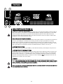
Intended to alert the user to the presence of uninsulated “dangerous voltage” within the product’s
enclosure that may be of sufficient magnitude to constitute a risk of electric shock to persons.
Intended to alert the user of the presence of important operating and maintenance (servicing)
instructions in the literature accompanying the product.
CAUTION: Risk of electrical shock — DO NOT OPEN!
CAUTION: To reduce the risk of electric shock, do not remove cover. No user serviceable parts inside. Refer
servicing to qualified service personnel.
WARNING: To prevent electrical shock or fire hazard, do not expose this appliance to rain or moisture. Before
using this appliance, read the operating guide for further warnings.
Este símbolo tiene el propósito, de alertar al usuario de la presencia de “(voltaje) peligroso” sin ais-
lamiento dentro de la caja del producto y que puede tener una magnitud suficiente como para constituir
riesgo de descarga eléctrica.
Este símbolo tiene el propósito de alertar al usario de la presencia de instruccones importantes sobre la
operación y mantenimiento en la información que viene con el producto.
PRECAUCION: Riesgo de descarga eléctrica ¡NO ABRIR!
PRECAUCION: Para disminuír el riesgo de descarga eléctrica, no abra la cubierta. No hay piezas útiles dentro.
Deje todo mantenimiento en manos del personal técnico cualificado.
ADVERTENCIA: Para evitar descargas eléctricas o peligro de incendio, no deje expuesto a la lluvia o humedad
este aparato Antes de usar este aparato, Iea más advertencias en la guía de operación.
Ce symbole est utilisé dans ce manuel pour indiquer à l’utilisateur la présence d’une tension dangereuse
pouvant être d’amplitude suffisante pour constituer un risque de choc électrique.
Ce symbole est utilisé dans ce manuel pour indiquer à l’utilisateur qu’il ou qu’elle trouvera d’importantes
instructions concernant l’utilisation et l’entretien de l’appareil dans le paragraphe signalé.
ATTENTION: Risques de choc électrique — NE PAS OUVRIR!
ATTENTION: Afin de réduire le risque de choc électrique, ne pas enlever le couvercle. Il ne se trouve à l’intérieur
aucune pièce pouvant être reparée par l’utilisateur. Confiez I’entretien et la réparation de l’appareil à un réparateur
Peavey agréé.
AVERTISSEMENT: Afin de prévenir les risques de décharge électrique ou de feu, n’exposez pas cet appareil à la
pluie ou à l’humidité. Avant d’utiliser cet appareil, lisez attentivement les avertissements supplémentaires de ce
manuel.
Dieses Symbol soll den Anwender vor unisolierten gefährlichen Spannungen innerhalb des Gehäuses
warnen, die von Ausreichender Stärke sind, um einen elektrischen Schlag verursachen zu können.
Dieses Symbol soll den Benutzer auf wichtige Instruktionen in der Bedienungsanleitung aufmerksam
machen, die Handhabung und Wartung des Produkts betreffen.
VORSICHT: Risiko — Elektrischer Schlag! Nicht öffnen!
VORSICHT: Um das Risiko eines elektrischen Schlages zu vermeiden, nicht die Abdeckung enfernen. Es befinden
sich keine Teile darin, die vom Anwender repariert werden könnten. Reparaturen nur von qualifiziertem
Fachpersonal durchführen lassen.
ACHTUNG: Um einen elektrischen Schlag oder Feuergefahr zu vermeiden, sollte dieses Gerät nicht dem Regen
oder Feuchtigkeit ausgesetzt werden. Vor Inbetriebnahme unbedingt die Bedienungsanleitung lesen.

3
IIMMPPOORRTTAANNTT SSAAFFEETTYY IINNSSTTRRUUCCTTIIOONNSS
WWAARRNNIINNGG::
When using electrical products, basic cautions should always be followed, including the following:
1. Read these instructions.
2. Keep these instructions.
3. Heed all warnings.
4. Follow all instructions.
5. Do not use this apparatus near water.
6. Clean only with a dry cloth.
7. Do not block any of the ventilation openings. Install in accordance with manufacturer’s instructions.
8. Do not install near any heat sources such as radiators, heat registers, stoves or other apparatus (including amplifiers)
that produce heat.
9. Do not defeat the safety purpose of the polarized or grounding-type plug. A polarized plug has two blades with one
wider than the other. A grounding type plug has two blades and a third grounding plug. The wide blade or third prong is
provided for your safety. If the provided plug does not fit into your outlet, consult an electrician for replacement of the
obsolete outlet.
10. Protect the power cord from being walked on or pinched, particularly at plugs, convenience receptacles, and the point
they exit from the apparatus.
11. Note for UK only: If the colors of the wires in the mains lead of this unit do not correspond with the terminals in your
plug‚ proceed as follows:
a) The wire that is colored green and yellow must be connected to the terminal that is marked by the letter E‚ the earth
symbol‚ colored green or colored green and yellow.
b) The wire that is colored blue must be connected to the terminal that is marked with the letter N or the color black.
c) The wire that is colored brown must be connected to the terminal that is marked with the letter L or the color red.
12. Only use attachments/accessories provided by the manufacturer.
13. Use only with a cart, stand, tripod, bracket, or table specified by the manufacturer, or sold with the apparatus. When a
cart is used, use caution when moving the cart/apparatus combination to avoid injury from tip-over.
14. Unplug this apparatus during lightning storms or when unused for long periods of time.
15. Refer all servicing to qualified service personnel. Servicing is required when the apparatus has been damaged in any
way, such as power-supply cord or plug is damaged, liquid has been spilled or objects have fallen into the apparatus,
the apparatus has been exposed to rain or moisture, does not operate normally, or has been dropped.
16. Never break off the ground pin. Write for our free booklet “Shock Hazard and Grounding.” Connect only to a power
supply of the type marked on the unit adjacent to the power supply cord.
17. If this product is to be mounted in an equipment rack, rear support should be provided.
18. Exposure to extremely high noise levels may cause a permanent hearing loss. Individuals vary considerably in suscep-
tibility to noise-induced hearing loss, but nearly everyone will lose some hearing if exposed to sufficiently intense noise
for a sufficient time. The U.S. Government’s Occupational Safety and Health Administration (OSHA) has specified the
following permissible noise level exposures:
Duration Per Day In Hours Sound Level dBA, Slow Response
890
692
495
397
2100
1 1⁄2 102
1105
1⁄2 110
1⁄4 or less 115
According to OSHA, any exposure in excess of the above permissible limits could result in some hearing loss. Ear plugs or protectors to the
ear canals or over the ears must be worn when operating this amplification system in order to prevent a permanent hearing loss, if exposure
is in excess of the limits as set forth above. To ensure against potentially dangerous exposure to high sound pressure levels, it is
recommended that all persons exposed to equipment capable of producing high sound pressure levels such as this amplification system be
protected by hearing protectors while this unit is in operation.
SSAAVVEE TTHHEESSEE IINNSSTTRRUUCCTTIIOONNSS!!

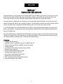
MMAAXX 445500
™™
PPRROOFFEESSSSIIOONNAALL BBAASSSS AAMMPPLLIIFFIIEERR
Congratulations on your purchase of the Peavey MAX
®
450. The MAX 450 includes an easy-to-use, three-
band active EQ with shiftable mid-range control and a contour control (for that smiley-face EQ curve).
These tone controls are so versatile you should be able to quickly dial up your own sound.
Also provided are a buffered tuner send jack, an electronically balanced XLR line out with its own level
control, pre-post EQ switch, and a ground lift switch. The XLR output is before the master volume control,
so you can adjust your stage volume without affecting the send to the main sound system.
A -10 dB input pad switch, footswitchable post-EQ effects loop, preamp output/power amp input patch
points, and the DDT
™
(speaker protection) enable/defeat switch add to the list of professional features
found in the MAX 450.
For more information on operation and specifications we suggest that you spend a few minutes to look
through this manual. Pay close attention to the safety precautions. They contain warnings that concern
the safety of both you and your amp. Thank you for buying Peavey!
FFeeaattuurreess::
• Compact top box design
• 450 Watts into 2Ω, 300 Watts into 4Ω, 170 Watts into 8Ω
• Three-band active EQ with shiftable mid-range control
• Contour control
• -10 dB pad switch (active/passive pickup switch)
• Buffered tuner send jack
• Footswitchable post-EQ effects loop
• Electronically balanced XLR jack
• Pre-/Post-EQ send switch for XLR jack
• Ground lift switch for XLR jack
• DDT
™
speaker protection with defeat switch
• Preamp out/power amp in jacks
4
ENGLISH

AACC PPOOWWEERR FFEEAATTUURREESS::
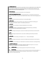
11.. RREEMMOOVVAABBLLEE AACC PPOOWWEERR CCOORRDD
This receptacle is for the IEC line cord (included), which provides AC power to the unit. Connect the line cord to
this connector and to a properly grounded AC supply. Damage to the equipment may occur if an improper line
voltage is used. (See voltage marking on unit.) Never remove or cut the ground pin of the line cord plug. This unit
is supplied with a properly rated line cord. When lost or damaged, replace this cord with one of the proper
ratings.
NNOOTTEE:: FFOORR UUKK OONNLLYY
As the colors of the wires in the mains lead of this apparatus may not correspond with the colored markings
identifying the terminals in your plug, proceed as follows: (1) The wire which is colored green and yellow must be
connected to the terminal which is marked by the letter E, or by the earth symbol, or colored green or green and
yellow. (2) The wire which is colored blue must be connected to the terminal which is marked with the letter N, or
the color black. (3) The wire which is colored brown must be connected to the terminal which is marked with the
letter L or color red.
22.. PPOOWWEERR SSWWIITTCCHH
This switch is used to turn the MAX 450 on or off. To turn the unit on, flip the switch to the “on” position.
33.. GGRROOUUNNDD PPOOLLAARRIITTYY SSWWIITTCCHH
Three-position, rocker-type switch, which for most applications should be operated in the center (zero) position. If
hum or noise is present with the ground switch in the center position, place the ground polarity switch to positive
or negative (+ or -) to minimize hum; should a problem continue, consult your authorized Peavey dealer, the
Peavey factory, or a qualified service technician.
NNoottee::
The ground switch is not available on 220/240 volt models.
44.. FFUUSSEE
The fuse is located within the fuse holder on the rear of the unit. If the fuse should fail,
IITT MMUUSSTT BBEE RREEPPLLAACCEEDD
WWIITTHH TTHHEE SSAAMMEE TTYYPPEE AANNDD VVAALLUUEE IINN OORRDDEERR TTOO AAVVOOIIDD DDAAMMAAGGEE TTOO TTHHEE EEQQUUIIPPMMEENNTT AANNDD TTOO PPRREEVVEENNTT VVOOIIDDIINNGG
TTHHEE WWAARRRRAANNTTYY
. If the amp repeatedly blows fuses, it should be taken to a qualified service center for repair.
NNOOTTEE:: TTHHEE FFUUSSEE SSHHOOUULLDD OONNLLYY BBEE RREEPPLLAACCEEDD WWHHEENN TTHHEE RREEMMOOVVAABBLLEE PPOOWWEERR CCOORRDD HHAASS BBEEEENN DDIISSCCOONNNNEECCTTEEDD
FFRROOMM IITTSS CCHHAASSSSIISS RREECCEEPPTTAACCLLEE ((11))..
5
2
4
1
3
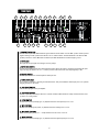
RReeaarr PPaanneell

55.. PPOOWWEERR//SSTTAATTUUSS LLEEDD
Located on front panel this LED illuminates green when the Power Switch is in the “ON” position and AC power is
supplied. During normal operation the LED also acts as a DDT indicator. The LED illuminates red when the DDT
speaker protection is active. When DDT is defeated, the LED will illuminate red when clipping occurs.
66.. IINNPPUUTT JJAACCKK
This input will accept signals from all types of bass pickups.
77.. IINNPPUUTT PPAADD SSWWIITTCCHH
Provided for instruments that have extremely high output, which can result in overdriving (distorting) the input
stage. Pressing the switch to its “in” or “active” position reduces the level of the input signal by 10 dB.
88.. BBRRIIGGHHTT SSWWIITTCCHH
Provides a preset boost to treble frequencies when pressed.
99.. TTUUNNEERR SSEENNDD JJAACCKK
A 1/4" jack is provided for connecting an instrument tuner. This jack is buffered off the input jack so it is just like
plugging directly into the tuner.
1100.. PPRREE GGAAIINN CCOONNTTRROOLL
Controls the input gain of the preamplifier.
1111.. CCOONNTTOOUURR CCOONNTTRROOLL
Provides a specially voiced EQ as the knob is rotated clockwise. When the knob is fully counterclockwise (set to
0), there is no voicing added.
1122.. LLOOWW CCOONNTTRROOLL
An active tone control (shelving type, ±15 dB) that varies the low frequency boost or cut.
1133.. MMIIDD CCOONNTTRROOLL
An active tone control (peak/notch, ±15 dB) that varies the midrange boost or cut.
1144.. MMIIDD SSHHIIFFTT CCOONNTTRROOLL
Selects the frequency band (200 — 2 kHz) that the mid control cuts or boosts.
1155.. HHIIGGHH CCOONNTTRROOLL
An active tone control (shelving type, ±15 dB) that varies the high frequency boost or cut.
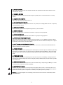
6
9
18 17 19 20 23 25 2621 22
6
7
10
8
11 12 13 14 15 16 5
24
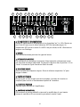
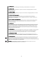
FFrroonntt PPaanneell

1166.. VVOOLLUUMMEE CCOONNTTRROOLL
Controls the overall volume level of the amplifier. The final level adjustment should be made after the desired
sound has been achieved.
1177.. LLIINNEE OOUUTT——XXLLRR JJAACCKK
Provides low impedance, electronically balanced signal for patching into a sound reinforcement or recording
console.
1188.. LLIINNEE OOUUTT LLEEVVEELL CCOONNTTRROOLL
Controls the output level of the balanced line out.
1199.. PPRREE--//PPOOSSTT--EEQQ SSEELLEECCTT SSWWIITTCCHH
Allows selection between a Pre-EQ (switch set to the “out” position) or a Post-EQ (switch set to the “in” position)
send to the XLR line out jack.
2200.. GGRROOUUNNDD LLIIFFTT SSWWIITTCCHH
Provided to lift the ground on the XLR jack when ground loops are encountered.
2211.. EEFFFFEECCTTSS SSEENNDD JJAACCKK
Output for supplying signals to external low-level effects or signal processing equipment.
2222.. EEFFFFEECCTTSS RREETTUURRNN JJAACCKK
Input for returning signals from external low-level effects or signal processing equipment.
2233.. EEFFFFEECCTTSS LLOOOOPP RREEMMOOTTEE SSWWIITTCCHH JJAACCKK
This jack accommodates the remote footswitch (optional part number 00051000 ON/OFF single button switch),
which is used to remove the effects loop from the signal path. The remote footswitch essentially acts as a bypass
to punch in or punch out from your external effects.
2244.. DDDDTT
™™
SSPPEEAAKKEERR PPRROOTTEECCTTIIOONN DDEEFFEEAATT SSWWIITTCCHH
DDT
™
speaker protection is defeated when the push button is in the “in” position. We recommend that DDT be
enabled at all times to protect the speakers.
2255.. PPRREEAAMMPP OOUUTT JJAACCKK
This 1/4" jack is used to route the preamp signal to external inputs, such as the input of an additional power amp.
The signal is post volume control. Use of this jack does not defeat the signal to the MAX 450 amp (some volume
difference may be noticed due to the impedance change experienced when adding an external unit to the signal
patch).
2266.. PPOOWWEERR AAMMPP IINN JJAACCKK
This 1/4" jack is used to input an external signal to the power amp section of the MAX 450. Using this jack will
disconnect any signal from the preamp section. Using this jack along with the preamp out jack creates a possible
second effects loop.
2277.. PPOOWWEERR CCOORRDD RREETTAAIINNEERRSS
Use the Power Cord Retainers to wrap and store your cable while storing or transporting your MAX 450. It is best
to disconnect the cord from the unit before wrapping.
2288.. SSPPEEAAKKEERR OOUUTTPPUUTT JJAACCKKSS
These two 1/4" jacks provide the powered signal from the amplifier. Each connector is electrically the same (in
parallel). Use one of the jacks to connect your speaker cabinet and the other to add a second speaker cabinet in
parallel. The minimum speaker load impedance is 2 Ohms (or two 4-Ohm speakers in parallel).
WWaarrnniinngg::
To prevent the amplifier from overheating, the front fan and rear-located vents should always remain
clear of obstructions.
7

8
SSYYSSTTEEMM SSPPEECCIIFFIICCAATTIIOONNSS::
Mains Fuse = 8 amps
Mains Voltage = 120 VAC 60 Hz
Power Consumption = 350 watts
Hum and noise: Typically greater than -89 dB unweighted with
controls set as follows…
Pad = Passive
Bright = Normal
Pre gain = 5
Contour = 0
Low = 0
Mid = 0
Mid Shift = 1kHz
High = 0
Volume = 5
PPOOWWEERR AAMMPPLLIIFFIIEERR SSEECCTTIIOONN::
PPRROOTTEECCTTIIOONN::
Electronic current limit protection circuit.
Thermal protection circuit.
D.C. crowbar protection circuit.
DDT speaker protection circuit with defeat switch.
Variable speed fan, thermally controlled
GGEENNEERRAALL IINNFFOORRMMAATTIIOONN::
Minimum load = 2 Ohms
Input sensitivity: 1.0 VRMS
Two 1/4" speaker jacks in parallel
RRAATTEEDD PPOOWWEERR OOUUTTPPUUTT::
450 Watts (30.00 V RMS) into 2 Ohms
300 Watts (34.64 V RMS) into 4 Ohms
170 Watts (36.88 V RMS) into 8 Ohms
TTYYPPIICCAALL PPOOWWEERR OOUUTTPPUUTT
475 Watts (30.82 V RMS) into 2 Ohms
with no more than 1% THD+N
308 Watts (35.10 V RMS) into 4 Ohms
with no more than 1% THD+N
177 Watts (37.63 V RMS) into 8 Ohms
with no more than 1% THD+N
NNOOIISSEE::
Typically greater than 102 dB below full power @
8 Ohms unweighted
DDDDTT DDyynnaammiicc RRaannggee::
Typically greater than +15 dB
FFRREEQQUUEENNCCYY RREESSPPOONNSSEE::
+0/-0.61 dB, 100mW to 160 W RMS, 20 Hz to 20 kHz
(8 Ohm load, typically below 0.2% THD+N)
PPRREEAAMMPPLLIIFFIIEERR SSEECCTTIIOONN::
SSEETTTTIINNGGSS FFOORR MMEEAASSUURREEMMEENNTTSS UUNNLLEESSSS OOTTHHEERRWWIISSEE NNOOTTEEDD::
Pad = out (Passive)
Bright = out (Normal)
Pre-Gain = 5 (12 o’clock)
Contour = 0 (fully counterclockwise)
Bass = 0 (12 o’clock)
Mid = 0 (12 o’clock)
Mid Shift = 0 (12 o’clock)
High = 0 (12 o’clock)
Master Volume = 10 (fully Clockwise)
Line Out Level = 10 (fully Clockwise)
IINNPPUUTT SSEENNSSIITTIIVVIITTYY ((LLeevveell ttoo aacchhiieevvee ffuullll ppoowweerr))::
With Pad Out...
Nominal input: 100 mV RMS
Minimum input: 9 mV(pre gain and master fully CW)
Maximum input: 3.0 V(maximum signal at input before
clipping occurs)
WWiitthh PPaadd --1100 ddBB iinn::
Nominal input: 315 mV RMS
Minimum input: 28 mV (pre gain and master fully CW)
Maximum input: 9 V (maximum signal at input before
clipping occurs)
EEQQUUAALLIIZZAATTIIOONN::
Bright boost: + 8 dB @ 5 kHz
Contour: Special frequency compensation
Bass: ± 15 dB @ 30 Hz, Shelving type Eq
Mid : ± 15 dB @ 200 @ 2 kHz (Mid shift control determines
center frequency)
Mid Shift: 200 to 2 kHz
High: ±15 dB @ 8 kHz, Shelving type Eq
TTUUNNEERR SSEENNDD::
Instrument level through a buffer
LLIINNEE OOUUTT::
-∞ to -10 dB (for nominal input).
Level is dependent on level control setting and pre gain setting
EEFFFFEECCTTSS LLOOOOPP::
Set for -10 dB (0.315 V RMS) with pre @ 5, Master @ 10
Controlled via footswitch, ground tip to defeat.
PPRREEAAMMPP OOUUTTPPUUTT::
1 V RMS nominal
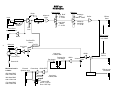
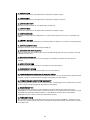
MMAAXX
®®
445500
SSPPEECCIIFFIICCAATTIIOONNSS

Input
Tuner Send
Instrument Level
Buffer
-10 db Pad
In/Out
-10 db Pad
Gain
Bright
Contour
Infrasonic
Filter
Shelving EQ
Low Shelf
(Bass)
+/- 15 dB
High Shelf
(Treble)
+/- 15 dB
Buffer
Effects
Send
Effects Loop
-10 dB, 0,
315 VRMS
Effects
Return
Effects Loop
Footswitch
Switch Logic
Buffer
Volume
CW
Buffer
Line Level
1 VRMS, 0dB
Line Level
1 VRMS, 0dB
PreAmp Out
Full Range
Pwr Amp In
Status LED
Green = Pwr On
Red = DDT/Clip
GN
DDT Defeat
Buffer/DDT
Power Amp
External
Speaker Jack
RD
Pre EQ
Post EQ
Pre/Post EQ
Select
Balanced
Line Out
Ground Lift
1
3
2
Minimum Load is
2 Ohms:
450 Watts RMS
with 2 Ohm load
300 Watts RMS
with 4 Ohm load
170 Watts RMS
with 8 Ohm load
1
2
Pre-
Gain
Midrange
Midrange
Shift
200HZ - 2KHZ
Midrange
Cut/Boost
+/- 15 dB
+
-
CW
Line Level
Out
Line Drivers
MMAAXX
®®
445500
BBlloocckk DDiiaaggrraamm
9

10
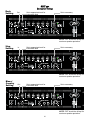
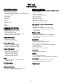
NOTE: “DDT should be utilized for
maximum speaker protection”
NOTE: “DDT should be utilized for
maximum speaker protection”
Rock
Setting
Out
Set to necessary
Set to appropriate level for
instrument used
Blues/
Country
Setting
Set to necessary
Set to appropriate level for
instrument used
NOTE: “DDT should be utilized for
maximum speaker protection”
In
Slap
Setting
Set to necessary
Set to appropriate level for
instrument used
Out
MMAAXX
®®
445500
RReeccoommmmeenndd SSeettttiinnggss

MMAAXX
®®
445500
AAmmpplliiffiiccaaddoorr pprrooffeessiioonnaall ppaarraa bbaajjoo
Felicitaciones por tu compra del MAX
®
450 de Peavey. El MAX 450 incluye un ecualizador activo de tres
bandas con control de cambio de medios y control de silueta que es fácil de usar (para lograr esa curva
de ecualización de cara feliz). Estos controles de tono son tan versátiles que podrás obtener tu sonido
muy rápidamente.
También se incluyen entradas de afinador, una salida de nivel de línea XLR balanceada electrónicamente y
que tiene su propio control de nivel, control de ecualización pre y post, así como un interruptor de tierra.
La salida XLR va antes del control de volumen para que puedas ajustar tu volumen de escenario sin
afectar el envío del sistema de sonido principal.
Un interruptor de pad de 10 dB, circuito de efectos post EQ controlable por pedal, puntos de parcheo
salida de preamp/entrada de ampli de poder, y un interruptor activar/cancelar para el sistema DDT
™
de
protección de bocinas se añaden a la lista de características profesionales encontradas en el MAX 450.
Para más información sobre la operación y las especificaciones te sugerimos que tomes unos minutos
para leer este manual. Presta mucha atención a las precauciones de seguridad. Contienen avisos que
conciernen tu seguridad y la de tu ampli. ¡Gracias por comprar Peavey!
CCaarraacctteerrííssttiiccaass::
• Diseño compacto de caja superior
• 450 Wats a 2Ω, 300 Wats a 4Ω, 170 Wats a 8Ω.
• Ecualizador activo de tres bandas con control cambiable de medios
• Interruptor de pad de 10 dB (interruptor de pastilla activa/no-activa)
• Conector amortiguado para envío de afinador
• Circuito de efectos por EQ controlable por pedal
• Entrada XLR balanceada electrónicamente
• Interruptor de envío para salida XLR Pre-/post EQ
• Interruptor de levantamiento de tierra para salida XLR
• Protección para bocinas DDT
™
con interruptor de cancelación
• Conectores salida de preamp/entrada de ampli de poder
11
ESPAÑOL

CCAARRAACCTTEERRÍÍSSTTIICCAASS DDEE PPOODDEERR CCAA::
11.. CCAABBLLEE DDEE PPOODDEERR CCAA IINNTTEERRCCAAMMBBIIAABBLLEE
Esta entrada es para el cable de línea IEC (incluido), mismo que provee poder CA a la unidad. Conecta el cable de
línea a este conector y a un suministro de CA propiamente aterrizado. El equipo puede dañarse si se usa voltaje
de línea inapropiado. (Ver marcación de voltaje en la unidad). Nunca quites ni cortes el alfiler de tierra del
conector del cable de línea. Esta unidad viene con un cable de marcación correcta. Si se pierde o daña el cable,
reemplázalo con uno de las marcaciones correcta.
NNOOTTAA:: PPAARRAA EELL RREEIINNOO UUNNIIDDOO SSOOLLAAMMEENNTTEE
Ya que los colores de los cables en la sección maestra de este aparato pueden no corresponder a las marcaciones
de colores que identifiquen las unidades de tu conector, procede como sigue: (1) El cable de color verde y
amarillo debe ser conectado a la terminal que está marcada con la letra E, o por el símbolo de tierra, o del color
verde o verde y amarillo. (2) El cable de color azul debe conectarse a la terminal marcada con la letra N, o el color
negro. (3) El cable de color café debe conectarse a la terminal marcada con la letra L o el color rojo.
22.. IINNTTEERRRRUUPPTTOORR DDEE PPOODDEERR
Éste es usado para encender o apagar el MAX 450. Para encender la unidad, pon el interuptor en la posición on.
33.. IINNTTEERRRRUUPPTTOORR DDEE PPOOLLAARRIIDDAADD DDEE TTIIEERRRRAA
Un interruptor de tres posiciones, tipo mecedora, que para la mayoría de las aplicaciones debe ser operado en la
posición central (cero). Si se presenta ruido o hum con el interruptor en la posición central, coloca el interruptor
hacia el positivo o negativo (+ o -) para minimizar el ruido; si el problema continuase consulta con tu vendedor
autorizado de Peavey, la fábrica Peavey, o un técnico de servicio calificado.
NNoottaa::
El interruptor de tierra no está
disponible en los modelos de 220/240 Voltios.
44.. FFUUSSIIBBLLEE
El fusible está localizado dentro del compartimento de fusible en la parte trasera de la unidad. Si el fusible
fallase,
DDEEBBEE SSEERR RREEEEMMPPLLAAZZAADDOO CCOONN UUNNOO DDEELL MMIISSMMOO TTIIPPOO,, CCAALLIIDDAADD YY VVAALLOORR PPAARRAA PPOODDEERR EEVVIITTAARR CCUUAALLQQUUIIEERR
DDAAÑÑOO AA LLAA UUNNIIDDAADD YY PPAARRAA QQUUEE NNOO SSEE CCAANNCCEELLEE LLAA GGAARRAANNTTÍÍAA..
Si el ampli quema fusibles continuamente, debe
ser llevado a un centro de servicio calificado para su reparación.
NNOOTTAA:: EELL FFUUSSIIBBLLEE SSÓÓLLOO DDEEBBEE SSEERR RREEEEMMPPLLAAZZAADDOO CCUUAANNDDOO EELL CCAABBLLEE DDEE CCOORRRRIIEENNTTEE HHAAYYAA SSIIDDOO DDEESSCCOONNEECCTTAADDOO
DDEE SSUU RREECCEEPPTTÁÁCCUULLOO EENN EELL CCHHAASSÍÍSS ((11))..
12
2
4
1
3
PPaanneell TTrraasseerroo

55.. LLEEDD DDEE EESSTTAADDOO DDEE PPOODDEERR
Localizado en el panel frontal este LED se ilumina de verde cuando el interruptor de poder esté en la posición ON
y se esté suministrando poder CA. Durante la operación normal el LED también actúa como indicador de DDT. El
LED se iluminará de rojo cuando esté activada la protección de bocinas DDT. Cundo se cancele la DDT, el LED se
iluminará de rojo si ocurre la saturación.
66.. CCOONNEECCTTOORR DDEE EENNTTRRAADDAA
Esta entrada acepta señales de todo tipo de pastillas (micrófonos) de bajo.
77.. EENNTTRRAADDAA DDEE IINNTTEERRRRUUPPTTOORR DDEE PPAADD
Incluido para instrumento que tienen un nivel de salida extremadamente alto, la cual puede causar es distorsión
en la etapa de entrada. Oprime el interruptor a su posición de activación para reducir el nivel de entrada por
10 dB.
88.. IINNTTEERRRRUUPPTTOORR DDEE BBRRIILLLLAANNTTEEZZ
Provee un aumento predeterminado de agudos al ser oprimido.
99.. CCOONNEECCTTOORR DDEE EENNVVÍÍOO AA AAFFIINNAADDOORR
Una entrada de 1/4 se incluye para conectar un afinador de instrumento. Este conector es paralelo al de entrada
para que la conexión se haga directamente al afinador.
1100.. CCOONNTTRROOLL DDEE PPRREE--GGAANNAANNCCIIAA
Controla la ganancia de entrada del preamplificador.
1111.. CCOONNTTRROOLL DDEE SSIILLUUEETTAA
Provee un ecualizador ajustado especialmente al ir girando la perilla hacia la derecha. Cuando la perilla está
totalmente hacia la izquierda (en 0), no hay ecualización añadida.
1122.. CCOONNTTRROOLL DDEE GGRRAAVVEESS
Un control de tono activo (tipo shelving, ±15 dB) que varía el aumento o corte de la frecuencia grave.
1133.. CCOONNTTRROOLL DDEE MMEEDDIIOOSS
Un control de tono activo (pico/corte, ±15 dB) que varía el aumento o corte de las frecuencias medias.
1144.. CCOONNTTRROOLL DDEE MMEEDDIIOOSS
Selecciona la banda de frecuencia (200 - 2 kHz) que el control de medios corta o aumenta.
13
9
18 17 19 20 23 25 2621 22
6
7
10
8
11 12 13 14 15 16 5
24
PPaanneell FFrroonnttaall

1155.. CCOONNTTRROOLL DDEE AAGGUUDDOOSS
Un control de tono activo (tipo shelving, ±15 dB) que varía el aumento o corte de las frecuencias agudas.
1166.. CCOONNTTRROOLL DDEE VVOOLLUUMMEENN
Controla el volumen general del amplificador. El nivel final de ajuste debe ser hecho después de que se ha
logrado el sonido deseado.
1177.. CCOONNEECCTTOORR XXLLRRSSAALLIIDDAA DDEE LLÍÍNNEEAA
Provee un señal balanceada y de baja impedancia para parchar a una consola de refuerzo de sonido o grabación.
1188.. CCOONNTTRROOLL DDEE NNIIVVEELL DDEE SSAALLIIDDAA DDEE LLÍÍNNEEAA
Controla el nivel de salida de la salida balanceada.
1199.. IINNTTEERRRRUUPPTTOORR DDEE SSEELLLLEECCCCIIÓÓNN PPRREE//PPOOSSTT EEQQ
Permite la selección entre un EQ-Pre (interruptor en la posición levantada) o EQ-Post (interruptor en la posición
oprimida) que va al conector de salida XLR de línea.
2200.. IINNTTEERRRRUUPPTTOORR DDEE LLEEVVAANNTTAAMMIIEENNTTOO DDEE TTIIEERRRRAA
Incluido para levantar la tierra a través del conector XLR cuando se encuentran circuitos de tierra.
2211.. CCOONNEECCTTOORR DDEE EENNVVÍÍOO DDEE EEFFEECCTTOOSS
Salida para suministrar señales a efectos externos de bajo nivel o procesadores de señal.
2222.. CCOONNEECCTTOORR DDEE RREETTOORRNNOO DDEE EEFFEECCTTOOSS
Entrada para regresar señales de unidades de efecto de bajo nivel o equipo de procesamiento.
2233.. CCOONNEECCTTOORR PPAARRAA IINNTTEERRRRUUPPTTOORR RREEMMOOTTOO DDEE CCIIRRCCUUIITTOO DDEE EEFFEECCTTOOSS
Este conector sirve para el pedal remoto (parte opcional número 00051000/interruptor ON/OFF de botón
sencillo), que es usado para quitar el circuito de efecto del paso de señal. El pedal remoto actúa esencialmente
como un método para activar o cancelar el efecto en la señal.
2244.. IINNTTEERRRRUUPPTTOORR PPAARRAA CCAANNCCEELLAACCIIÓÓNN DDEE PPRROOTTEECCCCIIÓÓNN DDEE BBOOCCIINNAASS
La protección DDT es cancelada cuando este botón esté oprimido. Recomendamos que se active la DDT todo el
tiempo para proteger las bocinas.
2255.. CCOONNEECCTTOORR DDEE SSAALLIIDDAA DDEE PPRREEMMPPLLII
Este conector de 1/4 se usa para enviar la señal del preampli a las entradas externas, como la entrada de un
ampli de poder adicional. La señal es post control de volumen. El uso de este conector no cancela la señal del
ampli MAX 450 (puede notarse alguna diferencia de volumen a causa del cambio de impedancia que sucede al
añadirse una unidad externa a la señal).
2266.. EENNTTRRAADDAA DDEE AAMMPPLLII DDEE PPOODDEERR
Esta entrada de 1/4 se usa para recibir una señal externa a la sección de ampli de poder del MAX 450. El uso de
este conector desconectará cualquier señal de la sección de preamp. El uso de este conector junto al de la salida
de preamp puede causar un segundo circuito de efecto.
2277.. RREETTEENNCCIIÓÓNN PPAARRAA CCAABBLLEE DDEE PPOODDEERR
Usa los retenedores para enrollar y guardar tu cable cuando transportes o almacenes tu MAX 450. Lo mejor es
desconectar el cable de la unidad antes de enrollarlo.
2288.. EEssttooss ddooss ccoonneeccttoorreess ddee 11//44 pprroovveeeenn uunnaa sseeññaall ddee ppooddeerr ppaarraa eell aammpplliiffiiccaaddoorr..
Cada conector es igual eléctricamente (en paralelo). Usa uno de los conectores para conectar tu gabinete de
bocina y otro para añadir un segundo gabinete de bocina en paralelo. La mínima impedancia de carga de bocina
es de 2 Ohmios (o dos bocinas de 4 Ohmios en paralelo).
PPrreeccaauucciióónn::
para prevenir que el amplificador se sobre caliente, el ventilador frontal y las ventilas traseras deben
estar libres de obstrucción.
14

15
EESSPPEECCIIFFIICCAACCIIOONNEESS DDEELL SSIISSTTEEMMAA
Fusible principal = 8 amps
Voltaje = 120 VAC 60 Hz
Consumo de poder = 350 wats
Hum y ruido: Típicamente mayor que -89 dB
sin peso con controles ajustados como sigue:
Pad = pasivo
Brillante = Normal
Pre ganancia = 5
Silueta = 0
Graves = 0
Medios = 0
Cambio de Medios = 1kHz
Agudos = 0
Volumen = 5
SSEECCCCIIÓÓNN DDEE AAMMPPLLIIFFIICCAADDOORR DDEE PPOODDEERR::
PROTECCIÓN:
Circuito de protección de límite de corriente electrónica
Circuito de protección termal
Circuito de protección de barra de C.D.
Circuito de protección de bocina DDT
con interruptor de cancelación
Ventilador de velocidad variable,
con control por temperatura
INFORMACIÓN GENERAL:
Carga mínima = 2 ohmios
Sensibilidad de entrada: 1.0 VRMS
Dos conectores de bocina de 1/4" en paralelo
PODER CLASIFICADO DE SALIDA:
450 wats (30.00 V RMS) a 2 ohmios
300 wats (34.64 V RMS) a 4 ohmios
170 wats (36.88 V RMS) a 8 ohmios
PODER TÍPICO DE SALIDA
475 wats (30.82 V RMS) a 2 ohmios
con no más de 1% THD+N
308 wats (35.10 V RMS) a 4 ohmios
con no más de 1% THD+N
177 wats (37.63 V RMS) a 8 ohmios
con no más de 1% THD+N
RUIDO:
Típicamente mayor que 102 dB abajo
del poder máximo @ 8 ohmios sin peso
Rango Dinámico DDT:
Típicamente mayor que +15 dB
RESPUESTA DE FRECUENCIA:
+0/-0.61 dB, 100mW a 160 W RMS, 20 Hz a 20 kHz
(carga de 8 ohmios, típicamente menor que 0.2% THD+N)
SSEECCCCIIÓÓNN DDEE PPRREEAAMMPPLLIIFFIICCAADDOORR::
VALORES PARA MEDIDAS AL MENOS QUE SE INDIQUE LO
CONTRARIO:
Pad = salida (pasivo)
Brillante = salida (Normal)
Pre-gnancia = 5 (12 en el reloj)
Silueta = 0 (totalmente hacia la derecha)
graves = 0 (12 en el reloj)
medios = 0 (12 en el reloj)
Cambio de medios = 0 (12 en el reloj)
Agudos = 0 (12 en el reloj)
Volumen maestro = 10 (totalmente hacia la derecha)
Nivel de Salida de Línea = 10 (totalmente hacia la derecha)
SENSIBILIDAD DE ENTRADA (Nivel para lograr nivel máximo):
Con pad hacia afuera
Entrada nominal: 100 mV RMS
Entrada mínima: 9 mV(pre ganancia y master totalmente hacia
la derecha)
Entrada máxima: 3.0 V(señal máxima de entrada antes de
ocurrir saturación)
Con Pad -10 dB de entrada:
Entrada Nominal: 315 mV RMS
Entrada mínima: 28 mV (pre ganancia y master totalmente hacia
la derecha)
Entrada máxima: 9 V (señal máxima de entrada antes de ocurrir
saturación)
ECUALIZACIÓN:
Aumento de brillantez: + 8 dB @ 5 kHz
Silueta: Compensación especial de frecuencia
Graves: ± 15 dB @ 30 Hz, Ecualizador tipo shelving
medios : ± 15 dB @ 200 @ 2 kHz (cambio de medios determina
frecuencia central)
cambio de medios: 200 a 2 kHz
Agudos: ±15 dB @ 8 kHz, Ecualizador tipo shelving
ENVÍO DE AFINADOR:
Nivel de instrumento a través de un buffer
SALIDA DE LÍNEA:
-∞ to -10 dB (para enterada nominal).
El nivel es dependiente del valor del control de nivel y del valor
de pre-ganancia.
CIRCUITO DE EEFCTOS:
Ajustado pra -10 dB (0.315 V RMS) con pre @ 5, Master @ 10
Controlado a través del pedal, punta de tierra para cancelar
SALIDA DE PREAMP:
1 V RMS nominal
MMaaxx 445500
™™
EESSPPEECCIIFFIICCAACCIIOONNEESS

MMAAXX
®®
445500
AAMMPPLLIIFFIICCAATTEEUURR BBAASSSSEE
Nous vous félicitons pour l’achat de cet amplificateur Peavey MAX
®
450. Le MAX 450 possède un EQ actif
3-bandes avec réglage semi-paramétrique des mediums et un contrôle de contour (pour obtenir aisément
la populaire equalisation en V). Ces contrôles de tonalité assurent au MAX 450 une versatilité optimum
qui vous permettra de trouver rapidement votre son.
Vous disposez en plus d’une sortie accordeur et d’une sortie Line Out XLR symétrique (a transformateur)
avec controle de niveau, sélecteur Pré/Post EQ et sélecteur Ground Lift. Cette sortie est située avant le
Master Volume; vous pouvez donc ajuster votre volume sur scène sans affecter le signal envoyé a la
sonorisation.
Atténuateur de -10 dB désengageable en entrée, boucle d’effet post-EQ enclenchable par footswitch,
sortie préampli ,entrée ampli de puissance et compression DDT complètent la liste des équipements du
MAX 450.
Pour plus d’informations sur le MAX 450, nous vous conseillons de lire attentivement ce manuel. Veuillez
lire attentivement les messages de précautions de ce manuel pour votre propre sécurité et celle de votre
matériel. Merci d’avoir choisi Peavey.
CCaarraacctteerriissttiiqquueess::
• Format tête d’ampli
• 450 Watts sous 2Ω, 300 Watts sous 4Ω, 170 Watts sous 8Ω
• EQ 3-bandes actif avec medium semi-paramétrique
• Controle de Contour
• Attenuateur -10 dB en entree (instrument actif/passif)
• Sortie accordeur
• Boucle d’effet post-EQ commutable
• Sortie Line Out symétrique XLR
• Sélecteur Pré-/Post-EQ pour la sortie XLR
• Sélecteur Ground lift pour la sortie XLR
• Limiteur DDT
™
(protection des HP) avec sélecteur
• Connexions Préamp out/Power-amp in
16
FRANCAIS

CCAARRAACCTTEERRIISSTTIIQQUUEESS DD’’AALLIIMMEENNTTAATTIIOONN::
11.. CCOONNNNEECCTTEEUURR IIEECC
Pour votre securite, un cordon d’alimentation assurant une bonne connexion a la terre est inclus. La connexion a
la terre ne doit etre deconnectee en aucune circonstance. Les risques de choc electrique sont considerablement
reduits lorsque la masse du chassis est correcte ment reliee a la terre. Reportez-vous aux inscriptions au dos de
votre amplificateur pour la tension d’alimentation necessaire.
22.. IINNTTEERRRRUUPPTTEEUURR DDEE MMIISSEE SSOOUUSS TTEENNSSIIOONN
Permet de mettre le MAX 450 sous tension. Pour cela, placer l’interrupteur sur “on”.
33.. SSEELLEECCTTEEUURR DDEE PPOOLLAARRIITTEE DDEE LLAA MMAASSSSEE
Absent sur les versions europeennes.
44.. FFUUSSIIBBLLEE
Si le fusible grille,
IILL DDOOIITT EETTRREE IIMMPPEERRAATTIIVVEEMMEENNTT RREEMMPPLLAACCEE PPAARR UUNN FFUUSSIIBBLLEE DDEE MMEEMMEE TTYYPPEE EETT DDEE MMEEMMEE
VVAALLEEUURR AAFFIINN DD’’EEVVIITTEERR TTOOUUTT DDOOMMMMAAGGEE AA LL’’AAPPPPAARREEIILL EETT LL’’AANNNNUULLAATTIIOONN DDEE LLAA GGAARRAANNTTIIEE
. Si l’amplificateur fait
régulièrement sauter son fusible, faites-le réparer par un réparateur agréé Peavey.
NNOOTTEE:: LLEE FFUUSSIIBBLLEE NNEE DDOOIITT EETTRREE RREEMMPPLLAACCEE QQUUEE LLOORRSSQQUUEE LLEE CCOORRDDOONN DD’’AALLIIMMEENNTTAATTIIOONN EESSTT DDEEBBRRAANNCCHHEE ((11))..
17
2
4
1
3
FFaaccee AArrrriieerree

55.. LLEEDD DDEE SSTTAATTUUTT EETT DD’’AALLIIMMEENNTTAATTIIOONN
Lorsque le commutateur d’alimentation est sur la position “on”, la LED s’illumine en
vert. Cette LED joue aussi le rôle d’indicateur DDT. Elle deviendra rouge si la
compression DDT se met en action. Si la DDT n’est pas utlisée, la LED s’illuminera en
rouge en cas d’écrêtage.
66.. EENNTTRREEEE
Cette entrée fonctionne pour tous les types de basses.
77.. AATTTTEENNUUAATTEEUURR DD’’EENNTTRREEEE
Cet atténuateur est destiné aux instruments à haut niveau de sortie pouvant causer
une saturation (ecrêtage) indésirable. En plaçant le sélecteur dans sa position “in” ou
“active” le niveau du signal d'entrée est réduit de 10 dB.
88.. SSEELLEECCTTEEUURR BBRRIIGGHHTT
Assure un boost des fréquences aigues. Placez le sélecteur en position “in” pour
engager le boost.
99.. SSOORRTTIIEE AACCCCOORRDDEEUURR
Une prise jack est fournie pour une sortie accordeur. Le niveau de la sortie est
compensé pour assurer un fonctionnement parfait de l’accordeur.
1100.. CCOONNTTRROOLLEE PPRREE GGAAIINN
Contrôle le gain d’entrée de l’amplificateur.
1111.. CCOONNTTRROOLLEE DDEE CCOONNTTOOUURR
Fait intervenir un voicing préétabli en tournant le contrôle dans le sens horaire.
Lorsque le contrôle est à 0, aucun voicing ne colore le son de l’ampli.
18
9
18 17 19 20 23 25 2621 22
6
7
10
8
11 12 13 14 15 16 5
24
FFaaccee AAvvaanntt

1122.. CCOONNTTRROOLLEE LLOOWW
Contrôle de tonalité actif (±15 dB) augmentant ou atténuant les fréquences graves.
1133.. CCOONNTTRROOLLEE MMIIDD
Contrôle de tonalité actif (±15 dB) augmentant ou atténuant les fréquences moyennes.
1144.. CCOONNTTRROOLLEE MMIIDD SSHHIIFFTT
Détermine la bande de fréquences sur laquelle agît le contrôle mid.
1155.. CCOONNTTRROOLLEE HHIIGGHH
Contrôle de tonalité actif (±15 dB) augmentant ou atténuant les fréquences aigues.
1166.. CCOONNTTRROOLLEE VVOOLLUUMMEE
Détermine le volume général de l’amplificateur. Ce contrôle doit être ajusté une fois que le son recherché a été
obtenu.
1177.. LLIINNEE OOUUTT——XXLLRR JJAACCKK
Offre une sortie à 600 Ohm symétrique pour connectez la tête à un système de sonorisation ou d'enregistrement.
1188.. CCOONNTTRROOLLEE LLIINNEE OOUUTT LLEEVVEELL
Détermine le niveau de sortie de la connexion Line Out (17).
1199.. SSEELLEECCTTEEUURR PPRREE--//PPOOSSTT--EEQQ SSEELLEECCTT
Permet de sélectionner le positionnement de la sortie Line Out: Pré-EQ (sélecteur en position “Out”) ou Post-EQ
(sélecteur en position “in”).
2200.. SSEELLEECCTTEEUURR GGRROOUUNNDD LLIIFFTT
Permet de déconnecter la masse de la sortie Line Out pour combattre les problèmes de boucle de masse
éventuels.
2211.. SSOORRTTIIEE EEFFFFEECCTTSS SSEENNDD
Sortie fournissant un signal bas niveau pour des effets ou processeurs externes.
2222.. EENNTTRREEEE EEFFFFEECCTTSS RREETTUURRNN
Retour des signaux bas niveau provenant d’effets ou processeurs externes.
2233.. PPRRIISSEE DDEE PPEEDDAALLEE DDEE CCOOMMMMAANNDDEE DDEE LLAA BBOOUUCCLLEE DD’’EEFFFFEETT
Cette prise est destinée au footswitch (optionel simple action ref n°00051000) retirant la boucle d'effet du chemin
du signal. La pédale de commande permet d'engager et désengager vos effets externes.
2244.. IINNTTEERRRRUUPPTTEEUURR DDEE LLAA PPRROOTTEECCTTIIOONN DDEESS HHPPSS DDDDTT
™™
Lorsque le sélecteur est en position “in”, la compression DDT
™
est désengagée. Nous recommandons de toujours
laisser la compression DDT engagée afin de protéger les haut-parleurs.
2255.. SSOORRTTIIEE PPRREEAAMMPP OOUUTT
Cette sortie permet de connecter la sortie du préampli à des unités externes tel un ampli de puissance
supplémentaire. Le sortie est située aprés le contrôle de volume. Lors de l’utilisation de cette connexion, le signal
du préampli reste acheminé à l’ampli du FireBass 700 (une différence de volume dûe à un changement
d’impédance issu de la connexion à une autre unité peut être perçue).
2266.. PPOOWWEERR AAMMPP IINN JJAACCKK
This 1/4" jack is used to input an external signal to the power amp section of the MAX 450. Using this jack will
disconnect any signal from the preamp section. Using this jack along with the preamp out jack creates a possible
second effects loop.
19

20
2277.. PPAATTTTEESS DD’’EENNRROOUULLEEMMEENNTT
Utilisez ces pattes pour enrouler votre cordon d’alimentation lors du rangement ou du transport de votre
amplificateur FireBass 700. Déconnectez le cordon d'alimentation de l’amplificateur avant de l’enrouler.
2288.. SSOORRTTIIEESS HHPP
Ces deux prises jacks constituent la sortie de l’amplificateur. Ces deux sorties sont identiques et connectées en
parallèle. L’impédance minimum en sortie de l'amplificateur doit être de 2 Ohm (soit deux enceintes de 4 Ohm en
parallèle).
AATTTTEENNTTIIOONN
: Pour éviter toute surchauffe de l’amplificateur, le ventilateur et les évents d’aération ne doivent en
aucun cas être obstrués.
Seite wird geladen ...
Seite wird geladen ...
Seite wird geladen ...
Seite wird geladen ...
Seite wird geladen ...
Seite wird geladen ...
Seite wird geladen ...
Seite wird geladen ...
-
 1
1
-
 2
2
-
 3
3
-
 4
4
-
 5
5
-
 6
6
-
 7
7
-
 8
8
-
 9
9
-
 10
10
-
 11
11
-
 12
12
-
 13
13
-
 14
14
-
 15
15
-
 16
16
-
 17
17
-
 18
18
-
 19
19
-
 20
20
-
 21
21
-
 22
22
-
 23
23
-
 24
24
-
 25
25
-
 26
26
-
 27
27
-
 28
28


Peavey 450 Benutzerhandbuch
- Kategorie
- Musikinstrumentenverstärker
- Typ
- Benutzerhandbuch
- Dieses Handbuch eignet sich auch für
in anderen Sprachen
- English: Peavey 450 User manual
- français: Peavey 450 Manuel utilisateur
- español: Peavey 450 Manual de usuario
Verwandte Artikel
-
Peavey Nitrobass Benutzerhandbuch
-
-
-
-
-
-
-
-
-