MSI 7C35 Bedienungsanleitung
- Kategorie
- Motherboards
- Typ
- Bedienungsanleitung
Dieses Handbuch ist auch geeignet für

I
Quick Start
Quick Start
Thank you for purchasing the MSI
®
MEG X570 ACE motherboard.
This Quick Start section provides demonstration diagrams about
how to install your computer. Some of the installations also provide
video demonstrations. Please link to the URL to watch it with the web
browser on your phone or tablet. You may have even link to the URL
by scanning the QR code.
Kurzanleitung
Danke, dass Sie das MSI
®
MEG X570 ACE Motherboard gewählt
haben. Dieser Abschnitt der Kurzanleitung bietet eine Demo zur
Installation Ihres Computers. Manche Installationen bieten auch
die Videodemonstrationen. Klicken Sie auf die URL, um diese
Videoanleitung mit Ihrem Browser auf Ihrem Handy oder Table
anzusehen. Oder scannen Sie auch den QR Code mit Ihrem Handy,
um die URL zu öffnen.
Présentation rapide
Merci d’avoir choisi la carte mère MSI
®
MEG X570 ACE. Ce manuel
fournit une rapide présentation avec des illustrations explicatives
qui vous aideront à assembler votre ordinateur. Des tutoriels vidéo
sont disponibles pour certaines étapes. Cliquez sur le lien fourni
pour regarder la vidéo sur votre téléphone ou votre tablette. Vous
pouvez également accéder au lien en scannant le QR code qui lui est
associé.
Быстрый старт
Благодарим вас за покупку материнской платы MSI
®
MEG
X570 ACE. В этом разделе представлена информация,
которая поможет вам при сборке комьютера. Для некоторых
этапов сборки имеются видеоинструкции. Для просмотра
видео, необходимо открыть соответствующую ссылку в
веб-браузере на вашем телефоне или планшете. Вы также
можете выполнить переход по ссылке, путем сканирования
QR-кода.

II
Quick Start
1
2
3
6
4
5
7
8
9
Youtube
https://youtu.be/Xv89nhFk1vc
CPU_FAN1
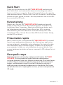
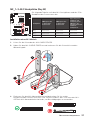
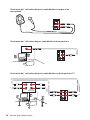
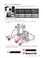
Installing a Processor/ Installation des Prozessors/ Installer un
processeur/ Установка процессора

III
Quick Start
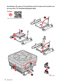
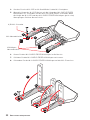
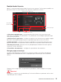
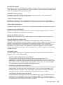
Important
If you are installing the screw-type CPU heatsink, please follow the figure below to
remove the retention module first and then install the heatsink.
Wenn Sie einen CPU-Kühler mit Schraubenbefestigung einsetzen, folgen Sie bitte
den Anweisungen unten um das Retention-Modul zu entfernen und den Kühler zu
installieren.
Si vous voulez installer un ventirad pour processeur à vis, veuillez suivre les
instructions ci-dessous pour dabord retirer le module de rétention puis installer le
ventirad.
,
. .
1
2
3

IV
Quick Start
http://youtu.be/T03aDrJPyQs
Youtube
DIMMA2 DIMMA2
DIMMB2
DIMMA1
DIMMA2
DIMMB1
DIMMB2
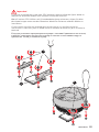
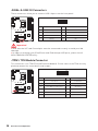
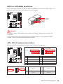
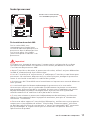
Installing DDR4 memory/ Installation des DDR4-Speichers/
Installer une mémoire DDR4/ Установка памяти DDR4

V
Quick Start
http://youtu.be/DPELIdVNZUI
Youtube
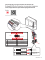
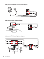
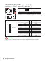
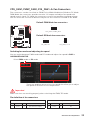
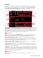
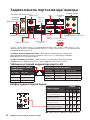
HDD LED
RESET SW
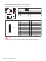
JFP1
HDD LED
HDD LED -
HDD LED +
POWER LED -
POWER LED +
POWER LED
1
2 10
9
+
+
+-
--
-
+
Power LED
HDD LED Reset Switch
Reserved
Power Switch
JFP1
1 HDD LED + 2 Power LED +
3 HDD LED - 4 Power LED -
5 Reset Switch 6 Power Switch
7 Reset Switch 8 Power Switch
9 Reserved 10 No Pin
RESET SW
POWER SW
POWER LED+
POWER LED-
HDD LED
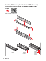
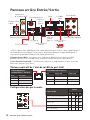
Connecting the Front Panel Header/ Anschließen der
Frontpanel-Stiftleiste/ Connecter un connecteur du panneau
avant/ Подключение разъемов передней панели

VI
Quick Start
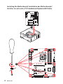
BAT1
1
2
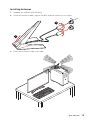
Installing the Motherboard/ Installation des Motherboards/
Installer la carte mère/ Установка материнской платы

VII
Quick Start
http://youtu.be/gkDYyR_83I4
Youtube
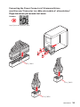
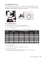
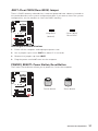
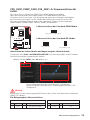
ATX_PWR1
CPU_PWR2
CPU_PWR1
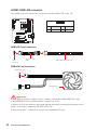
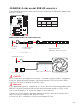
Connecting the Power Connectors/ Stromanschlüsse
anschliessen/ Connecter les câbles du module d’alimentation/
Подключение разъемов питания

VIII
Quick Start
http://youtu.be/RZsMpqxythc
Youtube
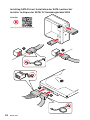
1
2
3
4
5
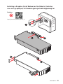
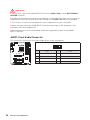
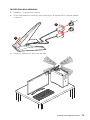
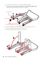
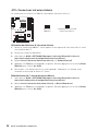
Installing SATA Drives/ Installation der SATA-Laufwerke/
Installer le disque dur SATA/ Установка дисков SATA

IX
Quick Start
http://youtu.be/mG0GZpr9w_A
Youtube
1
2
3
4
5
6
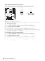
Installing a Graphics Card/ Einbau der Grafikkarte/ Installer
une carte graphique/ Установка дискретной видеокарты

X
Quick Start
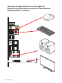
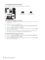
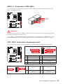
Connecting Peripheral Devices/ Peripheriegeräte/
Connecter un périphérique anschliessen/ Подключение
периферийных устройств

XI
Quick Start
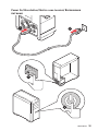
4
3
1
2
Power On/ Einschalten/ Mettre sous-tension/ Включение
питания

XII
Quick Start
NOTE

1
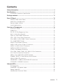
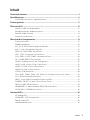
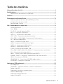
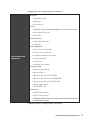
Contents
Contents
Safety Information ................................................................................................. 3
Specifications ......................................................................................................... 4
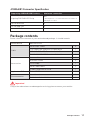
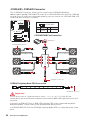
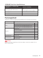
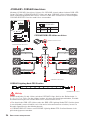
JCORSAIR1 Connector Specification .................................................................. 11
Package contents ................................................................................................ 11
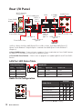
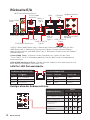
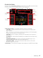
Rear I/O Panel ..................................................................................................... 12
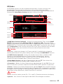
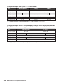
LAN Port LED Status Table................................................................................... 12
Audio Ports Configuration .................................................................................... 12
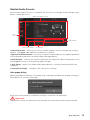
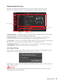
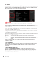
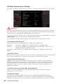
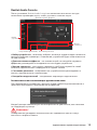
Realtek Audio Console ......................................................................................... 13
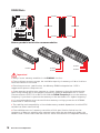
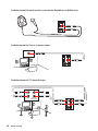
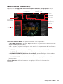
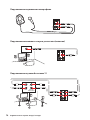
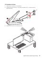
Installing Antennas ............................................................................................... 15
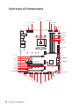
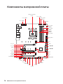
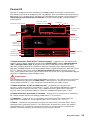
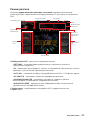
Overview of Components .................................................................................... 16
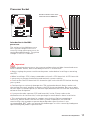
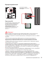
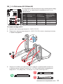
Processor Socket .................................................................................................. 17
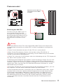
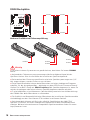
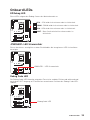
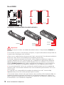
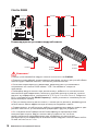
DIMM Slots ............................................................................................................ 18
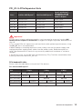
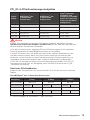
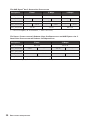
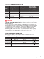
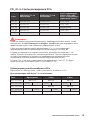
PCI_E1~5: PCIe Expansion Slots .......................................................................... 19
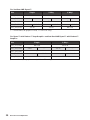
M2_1~3: M.2 Slots (Key M) ................................................................................... 21
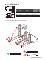
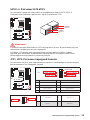
SATA1~4: SATA 6Gb/s Connectors ....................................................................... 23
JFP1, JFP2: Front Panel Connectors ................................................................... 23
CPU_PWR1~2, ATX_PWR1: Power Connectors ................................................... 24
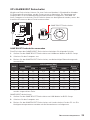
OC1: GAME BOOST Knob ..................................................................................... 25
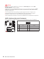
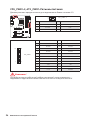
JAUD1: Front Audio Connector ............................................................................ 26
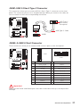
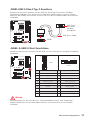
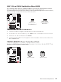
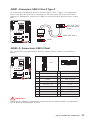
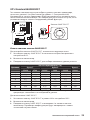
JUSB1: USB 3.2 Gen 2 Type-C Connector ............................................................ 27
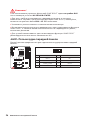
JUSB2~3: USB 3.2 Gen1 Connector ..................................................................... 27
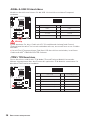
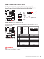
JUSB4~5: USB 2.0 Connectors ............................................................................. 28
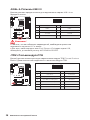
JTPM1: TPM Module Connector ........................................................................... 28
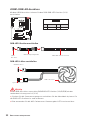
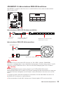
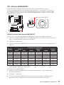
CPU_FAN1, PUMP_FAN1, SYS_FAN1~5: Fan Connectors ................................... 29
JCI1: Chassis Intrusion Connector ....................................................................... 30
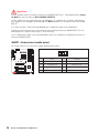
JBAT1: Clear CMOS (Reset BIOS) Jumper ........................................................... 31
POWER1, RESET1: Power Button, Reset Button ................................................. 31
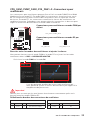
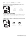
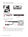
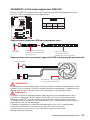
JRGB1: RGB LED connector ................................................................................. 32
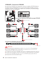
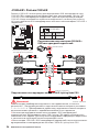
JRAINBOW1~2: Addressable RGB LED connectors ............................................. 33
JCORSAIR1: CORSAIR Connector ........................................................................ 34
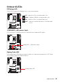
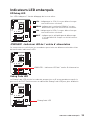
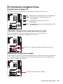
Onboard LEDs ...................................................................................................... 35
EZ Debug LED ....................................................................................................... 35
JPWRLED1: LED power input ............................................................................... 35
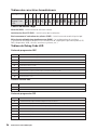
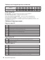
Debug Code LED ................................................................................................... 35
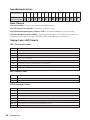
Hexadecimal Character Table .............................................................................. 36

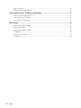
2
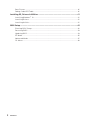
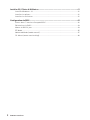
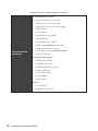
Contents
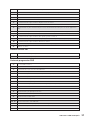
Boot Phases .......................................................................................................... 36
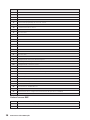
Debug Code LED Table ......................................................................................... 36
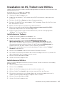
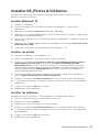
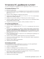
Installing OS, Drivers & Utilities ......................................................................... 41
Installing Windows
®
10 ......................................................................................... 41
Installing Drivers .................................................................................................. 41
Installing Utilities ................................................................................................. 41
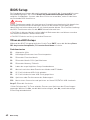
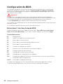
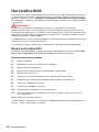
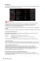
BIOS Setup ........................................................................................................... 42
Entering BIOS Setup ............................................................................................. 42
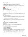
Resetting BIOS ...................................................................................................... 43
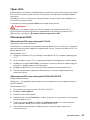
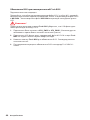
Updating BIOS ....................................................................................................... 43
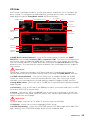
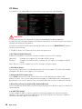
EZ Mode ................................................................................................................ 45
Advanced Mode .................................................................................................... 47
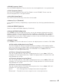
OC Menu................................................................................................................ 48

3
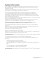
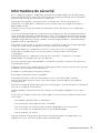
Safety Information
Safety Information
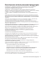
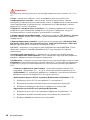
y The components included in this package are prone to damage from electrostatic
discharge (ESD). Please adhere to the following instructions to ensure successful
computer assembly.
y Ensure that all components are securely connected. Loose connections may cause
the computer to not recognize a component or fail to start.
y Hold the motherboard by the edges to avoid touching sensitive components.
y It is recommended to wear an electrostatic discharge (ESD) wrist strap when
handling the motherboard to prevent electrostatic damage. If an ESD wrist strap is
not available, discharge yourself of static electricity by touching another metal object
before handling the motherboard.
y Store the motherboard in an electrostatic shielding container or on an anti-static pad
whenever the motherboard is not installed.
y Before turning on the computer, ensure that there are no loose screws or metal
components on the motherboard or anywhere within the computer case.
y Do not boot the computer before installation is completed. This could cause
permanent damage to the components as well as injury to the user.
y If you need help during any installation step, please consult a certified computer
technician.
y Always turn off the power supply and unplug the power cord from the power outlet
before installing or removing any computer component.
y Keep this user guide for future reference.
y Keep this motherboard away from humidity.
y Make sure that your electrical outlet provides the same voltage as is indicated on the
PSU, before connecting the PSU to the electrical outlet.
y Place the power cord such a way that people can not step on it. Do not place anything
over the power cord.
y All cautions and warnings on the motherboard should be noted.
y If any of the following situations arises, get the motherboard checked by service
personnel:
Liquid has penetrated into the computer.
The motherboard has been exposed to moisture.
The motherboard does not work well or you can not get it work according to user
guide.
The motherboard has been dropped and damaged.
The motherboard has obvious sign of breakage.
y Do not leave this motherboard in an environment above 60C (140F), it may damage
the motherboard.

4
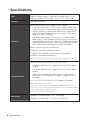
Specifications
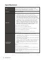
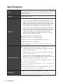
Specifications
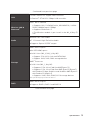
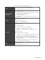
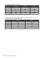
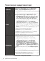
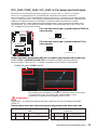
CPU
Supports 2nd and 3rd Gen AMD Ryzen™ / Ryzen™ with
Radeon™ Vega Graphics and 2nd Gen AMD Ryzen™ with
Radeon™ Graphics Desktop Processors for Socket AM4
Chipset AMD
®
X570 Chipset
Memory
y
4x DDR4 memory slots, support up to 128GB*
3rd Gen AMD Ryzen ™ Processors support DDR4 1866/
2133/ 2400/ 2667/ 2800/ 2933/ 3000/ 3066/ 3200 MHz by
JEDEC, and 2667/ 2800/ 2933/ 3000/ 3066/ 3200/ 3466/
3600/ 3733/ 3866/ 4000/ 4133/ 4266/ 4400/ 4533/ 4600
MHz by A-XMP OC MODE
2nd Gen AMD Ryzen ™ Processors, 1st and 2nd Gen
AMD Ryzen ™ with Radeon ™ Vega Graphics Processors
support DDR4 1866/ 2133/ 2400/ 2667/ 2800/ 2933/ 3000/
3066/ 3200 Mhz by JEDEC, and 2667/ 2800/ 2933/ 3000/
3066/ 3200/ 3466/ 3600 MHz by A-XMP OC MODE
y
Dual channel memory architecture
y
Supports non-ECC UDIMM memory
y
Supports ECC UDIMM memory (non-ECC mode)
y
Supports un-buffered memory
* Please refer www.msi.com for more information on compatible memory.
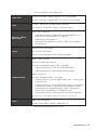
Expansion Slots
y 2x PCIe 4.0/ 3.0 x16 slots (PCI_E1, PCI_E3)
3rd Gen AMD Ryzen™ support PCIe 4.0 x16/x0, x8/x8
modes
2nd Gen AMD Ryzen™ support PCIe 3.0 x16/x0, x8/x8
modes
Ryzen™ with Radeon™ Vega Graphics and 2nd Gen
AMD Ryzen™ with Radeon™ Graphics support PCIe 3.0
x8 mode*
y 1x PCIe 4.0/ 3.0 x16 slot (PCI_E5, supports x4 mode)
y 2x PCIe 4.0/ 3.0 x1 slots**
* PCI_E3 slot is only available for 2nd and 3rd Gen AMD Ryzen™ processors.
** The PCIe x1 slots can not be used simultaneously. PCI_E2 will be unavailable
when installing the PCIe card in PCI_E4 slot.
***The speeds may vary for different devices
Multi-GPU
y Supports 2-Way NVIDIA
®
SLI
®
Technology
y Supports 3-Way AMD
®
CrossFire™ Technology
Continued on next page

5
Specifications
Continued from previous page
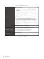
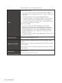
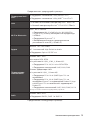
LAN
1x Intel
®
WGI211AT Gigabit LAN controller
1x Realtek
®
RTL8125 2.5 Gbps LAN controller
Wireless LAN &
Bluetooth
®
Intel
®
Wi-Fi 6 AX200
Supports 802.11 a/b/g/n/ac/ax, MU-MINO Rx, 2.4GHz-
5GHz (160MHz) up to 2.4Gbps
Supports Bluetooth
®
5
The Wireless module is pre-install in the M2_4 (Key-E)
slot
Audio
Realtek
®
ALC1220 Codec
y 7.1-Channel High Definition Audio
y Supports Optical S/PDIF output
Storage
AMD
®
X570 Chipset
y 4x SATA 6Gb/s ports
y 2x M.2 slots (M2_2/ M2_3, Key M)*
Support PCIe 4.0/ 3.0 x4 and SATA 6Gb/s
Support 2242/ 2260 /2280 storage devices
AMD
®
Processor
y 1x M.2 slot (M2_1, Key M)*
Supports PCIe 4.0 x4 (3rd Gen AMD Ryzen™)
Supports PCIe 3.0 x4 (2nd Gen AMD Ryzen™/ Ryzen™
with Radeon™ Vega Graphics and 2nd Gen AMD Ryzen™
with Radeon™ Graphics)
Supports 2242/ 2260 /2280/ 22110 storage devices
*The speeds may vary for different devices
RAID
AMD
®
X570 Chipset
y Supports RAID 0, RAID 1 and RAID 10
Continued on next page

6
Specifications
Continued from previous page
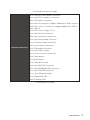
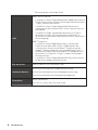
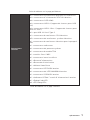
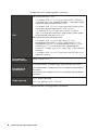
USB
AMD
®
X570 Chipset
3x USB 3.2 Gen2 (SuperSpeed USB 10Gbps) ports
(2 Type-A ports on the back panel, 1 Type-C internal
connector)
4x USB 3.2 Gen1 (SuperSpeed USB) ports through the
internal USB 3.2 Gen1 connectors
6x USB 2.0 (High-speed USB) ports (2 Type-A ports
on the back panel, 4 ports through the internal USB 2.0
connectors)
AMD
®
Processor
2x USB 3.2 Gen2 (3rd Gen AMD Ryzen™) or USB 3.2
Gen1 (2nd Gen AMD Ryzen™/ Ryzen™ with Radeon™
Vega Graphics and 2nd Gen AMD Ryzen™ with Radeon™
Graphics) ports (1x Type-A & 1x Type-C) on the back
panel
2x USB 3.2 Gen1 (SuperSpeed USB) Type-A ports on the
back panel
I/O Controller NUVOTON NCT6797 Controller Chip
Hardware Monitor
y CPU/ System/Chipset temperature detection
y CPU/ System/Chipset fan speed detection
y CPU/ System/Chipset fan speed control
Form Factor
y ATX Form Factor
y 12 in. x 9.6 in. (30.5 cm x 24.4 cm)
Continued on next page

7
Specifications
Continued from previous page
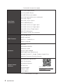
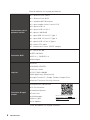
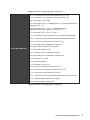
Internal Connectors
y 1x 24-pin ATX main power connector
y 2x 8-pin ATX 12V power connectors
y 4x SATA 6Gb/s connectors
y 2x USB 2.0 connectors (support additional 4 USB 2.0 ports)
y 2x USB 3.2 Gen 1 connectors (support additional 4 USB 3.2
Gen 1 ports)
y 1x USB 3.2 Gen 2 Type-C Port
y 1x 4-pin CPU fan connector
y 5x 4-pin system fan connectors
y 1x 4-pin water-pump connector
y 1x Front panel audio connector
y 2x System panel connectors
y 1x TPM module connector
y 1x Clear CMOS jumper
y 1x Chassis Intrusion connector
y 1x Power button
y 1x Reset button
y 1x Game Boost knob
y 1x 4-pin RGB LED connector
y 2x 3-pin RAINBOW LED connectors
y 1x 3-pin CORSAIR connector
y 1x 2-pin LED power input
y 1x Debug Code LED
y 4x EZ Debug LEDs
Continued on next page

8
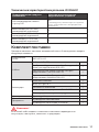
Specifications
Continued from previous page
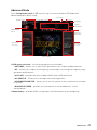
Back Panel
Connectors
y 1x Clear CMOS Button
y 1x Flash BIOS Button
y 1x WiFi/ Bluetooth module
y 1x PS/2 keyboard/ mouse combo port
y 2x USB 2.0 ports
y 2x USB 3.2 Gen 1 ports
y 2x LAN(RJ45) ports
y 1x USB 3.2 Gen 2/ 1 Type C port
y 1x USB 3.2 Gen 2/ 1 Type A port
y 2x USB 3.2 Gen 2 Type A ports
y 5x OFC audio jacks
y 1x Optical S/PDIF Out connector
BIOS Features
y 1x 256 Mb flash
y UEFI AMI BIOS
y ACPI 6.1, SM BIOS 2.8
y Multi-language
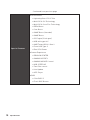
Software
y Drivers
y DRAGON CENTER
y Nahimic Audio
y CPU-Z MSI GAMING
y MSI App Player (BlueStacks)
y Google Chrome™ ,Google Toolbar, Google Drive
y Norton™ Internet Security Solution
Dragon Center
Features
y DRAGON OPTIMIZATION
y OC Performance
y Hardware Monitor
y True Color
y LAN Manager
y Mystic Light
y Live Update
Please refer to
http://download.msi.com/manual/
mb/DRAGONCENTER2.pdf
for more details.
Continued on next page
Seite laden ...
Seite laden ...
Seite laden ...
Seite laden ...
Seite laden ...
Seite laden ...
Seite laden ...
Seite laden ...
Seite laden ...
Seite laden ...
Seite laden ...
Seite laden ...
Seite laden ...
Seite laden ...
Seite laden ...
Seite laden ...
Seite laden ...
Seite laden ...
Seite laden ...
Seite laden ...
Seite laden ...
Seite laden ...
Seite laden ...
Seite laden ...
Seite laden ...
Seite laden ...
Seite laden ...
Seite laden ...
Seite laden ...
Seite laden ...
Seite laden ...
Seite laden ...
Seite laden ...
Seite laden ...
Seite laden ...
Seite laden ...
Seite laden ...
Seite laden ...
Seite laden ...
Seite laden ...
Seite laden ...
Seite laden ...
Seite laden ...
Seite laden ...
Seite laden ...
Seite laden ...
Seite laden ...
Seite laden ...
Seite laden ...
Seite laden ...
Seite laden ...
Seite laden ...
Seite laden ...
Seite laden ...
Seite laden ...
Seite laden ...
Seite laden ...
Seite laden ...
Seite laden ...
Seite laden ...
Seite laden ...
Seite laden ...
Seite laden ...
Seite laden ...
Seite laden ...
Seite laden ...
Seite laden ...
Seite laden ...
Seite laden ...
Seite laden ...
Seite laden ...
Seite laden ...
Seite laden ...
Seite laden ...
Seite laden ...
Seite laden ...
Seite laden ...
Seite laden ...
Seite laden ...
Seite laden ...
Seite laden ...
Seite laden ...
Seite laden ...
Seite laden ...
Seite laden ...
Seite laden ...
Seite laden ...
Seite laden ...
Seite laden ...
Seite laden ...
Seite laden ...
Seite laden ...
Seite laden ...
Seite laden ...
Seite laden ...
Seite laden ...
Seite laden ...
Seite laden ...
Seite laden ...
Seite laden ...
Seite laden ...
Seite laden ...
Seite laden ...
Seite laden ...
Seite laden ...
Seite laden ...
Seite laden ...
Seite laden ...
Seite laden ...
Seite laden ...
Seite laden ...
Seite laden ...
Seite laden ...
Seite laden ...
Seite laden ...
Seite laden ...
Seite laden ...
Seite laden ...
Seite laden ...
Seite laden ...
Seite laden ...
Seite laden ...
Seite laden ...
Seite laden ...
Seite laden ...
Seite laden ...
Seite laden ...
Seite laden ...
Seite laden ...
Seite laden ...
Seite laden ...
Seite laden ...
Seite laden ...
Seite laden ...
Seite laden ...
Seite laden ...
Seite laden ...
Seite laden ...
Seite laden ...
Seite laden ...
Seite laden ...
Seite laden ...
Seite laden ...
Seite laden ...
Seite laden ...
Seite laden ...
Seite laden ...
Seite laden ...
Seite laden ...
Seite laden ...
Seite laden ...
Seite laden ...
Seite laden ...
Seite laden ...
Seite laden ...
Seite laden ...
Seite laden ...
Seite laden ...
Seite laden ...
Seite laden ...
Seite laden ...
Seite laden ...
Seite laden ...
Seite laden ...
Seite laden ...
Seite laden ...
Seite laden ...
Seite laden ...
Seite laden ...
Seite laden ...
Seite laden ...
Seite laden ...
Seite laden ...
Seite laden ...
Seite laden ...
Seite laden ...
Seite laden ...
Seite laden ...
Seite laden ...
Seite laden ...
Seite laden ...
Seite laden ...
Seite laden ...
Seite laden ...
Seite laden ...
Seite laden ...
Seite laden ...
Seite laden ...
Seite laden ...
Seite laden ...
Seite laden ...
Seite laden ...
Seite laden ...
Seite laden ...
Seite laden ...
Seite laden ...
Seite laden ...
Seite laden ...
Seite laden ...
Seite laden ...
Seite laden ...
Seite laden ...
Seite laden ...
Seite laden ...
-
 1
1
-
 2
2
-
 3
3
-
 4
4
-
 5
5
-
 6
6
-
 7
7
-
 8
8
-
 9
9
-
 10
10
-
 11
11
-
 12
12
-
 13
13
-
 14
14
-
 15
15
-
 16
16
-
 17
17
-
 18
18
-
 19
19
-
 20
20
-
 21
21
-
 22
22
-
 23
23
-
 24
24
-
 25
25
-
 26
26
-
 27
27
-
 28
28
-
 29
29
-
 30
30
-
 31
31
-
 32
32
-
 33
33
-
 34
34
-
 35
35
-
 36
36
-
 37
37
-
 38
38
-
 39
39
-
 40
40
-
 41
41
-
 42
42
-
 43
43
-
 44
44
-
 45
45
-
 46
46
-
 47
47
-
 48
48
-
 49
49
-
 50
50
-
 51
51
-
 52
52
-
 53
53
-
 54
54
-
 55
55
-
 56
56
-
 57
57
-
 58
58
-
 59
59
-
 60
60
-
 61
61
-
 62
62
-
 63
63
-
 64
64
-
 65
65
-
 66
66
-
 67
67
-
 68
68
-
 69
69
-
 70
70
-
 71
71
-
 72
72
-
 73
73
-
 74
74
-
 75
75
-
 76
76
-
 77
77
-
 78
78
-
 79
79
-
 80
80
-
 81
81
-
 82
82
-
 83
83
-
 84
84
-
 85
85
-
 86
86
-
 87
87
-
 88
88
-
 89
89
-
 90
90
-
 91
91
-
 92
92
-
 93
93
-
 94
94
-
 95
95
-
 96
96
-
 97
97
-
 98
98
-
 99
99
-
 100
100
-
 101
101
-
 102
102
-
 103
103
-
 104
104
-
 105
105
-
 106
106
-
 107
107
-
 108
108
-
 109
109
-
 110
110
-
 111
111
-
 112
112
-
 113
113
-
 114
114
-
 115
115
-
 116
116
-
 117
117
-
 118
118
-
 119
119
-
 120
120
-
 121
121
-
 122
122
-
 123
123
-
 124
124
-
 125
125
-
 126
126
-
 127
127
-
 128
128
-
 129
129
-
 130
130
-
 131
131
-
 132
132
-
 133
133
-
 134
134
-
 135
135
-
 136
136
-
 137
137
-
 138
138
-
 139
139
-
 140
140
-
 141
141
-
 142
142
-
 143
143
-
 144
144
-
 145
145
-
 146
146
-
 147
147
-
 148
148
-
 149
149
-
 150
150
-
 151
151
-
 152
152
-
 153
153
-
 154
154
-
 155
155
-
 156
156
-
 157
157
-
 158
158
-
 159
159
-
 160
160
-
 161
161
-
 162
162
-
 163
163
-
 164
164
-
 165
165
-
 166
166
-
 167
167
-
 168
168
-
 169
169
-
 170
170
-
 171
171
-
 172
172
-
 173
173
-
 174
174
-
 175
175
-
 176
176
-
 177
177
-
 178
178
-
 179
179
-
 180
180
-
 181
181
-
 182
182
-
 183
183
-
 184
184
-
 185
185
-
 186
186
-
 187
187
-
 188
188
-
 189
189
-
 190
190
-
 191
191
-
 192
192
-
 193
193
-
 194
194
-
 195
195
-
 196
196
-
 197
197
-
 198
198
-
 199
199
-
 200
200
-
 201
201
-
 202
202
-
 203
203
-
 204
204
-
 205
205
-
 206
206
-
 207
207
-
 208
208
-
 209
209
-
 210
210
-
 211
211
-
 212
212
-
 213
213
-
 214
214
-
 215
215
-
 216
216
-
 217
217
-
 218
218
-
 219
219
-
 220
220
-
 221
221
-
 222
222
-
 223
223
-
 224
224


MSI 7C35 Bedienungsanleitung
- Kategorie
- Motherboards
- Typ
- Bedienungsanleitung
- Dieses Handbuch ist auch geeignet für
in anderen Sprachen
- français: MSI 7C35 Le manuel du propriétaire
Verwandte Papiere
-
MSI PRESTIGE X570 CREATION Bedienungsanleitung
-
MSI 7C34 Bedienungsanleitung
-
MSI 7C35 2.0 Bedienungsanleitung
-
-
MSI 7C37 v1.2 Bedienungsanleitung
-
MSI MPG X570 GAMING PLUS Bedienungsanleitung
-
MSI X570-A PRO Bedienungsanleitung
-
MSI TRX40 PRO 10G Bedienungsanleitung
-
MSI B450 GAMING PRO CARBON AC Benutzerhandbuch
-
MSI MS-7B85 Bedienungsanleitung