METREL MD 9235 Benutzerhandbuch
- Kategorie
- Messen, Testen
- Typ
- Benutzerhandbuch

METREL MD 9235
TRMS Power Clamp Meter, 3-Phase,
Unbalanced-Load
MD 9235
User Manual
Bedienungsanleitung
Version 1.2, Code no. 20 752 002

2
Distributor:
METREL d.d.
Ljubljanska cesta 77
1354 Horjul
Slovenia
E-mail: [email protected]
web site: http://www.metrel.si/
Metrel GmbH
Mess und Prüftechnik
Orchideenstrasse 24
90542 Eckental -Brand
Germany
E-mail: [email protected]
Internet: http://www.metrel.de/
Metrel UK Ltd.
Test & Measurement
Unit 16, 1st Qtr Business Park,
Blenheim Road,
Epsom,
Surrey
KT19 9QN
Great Britain
E-mail: [email protected]
Internet: http://www.metrel.co.uk/
© 2012 – 2016 METREL
Mark on your equipment certifies that this equipment meets the requirements of the EC
(European Community) regulations concerning safety and electromagnetic compatibility.
No part of this publication may be reproduced or utilized in any form or by any means
without permission in writing from METREL.

MD 9235 Clamp Meter Series Table of contents / Inhalt
3
Table of contents/ Inhalt
English
1 Safety ........................................................................................................................... 4
2 Cenelec Directives ........................................................................................................ 5
3 Product Description ...................................................................................................... 6
4 Operation ...................................................................................................................... 7
5 Specifications.............................................................................................................. 17
6 Maintenance ............................................................................................................... 21
Deutsch
1.Sicherheitsbestimmungen .......................................................................................... 23
2 Cenelec-Richtlinien ..................................................................................................... 24
3 Produktbeschreibung .................................................................................................. 25
4 Betrieb ........................................................................................................................ 26
5 Spezifikationen ........................................................................................................... 36
6 Wartung ...................................................................................................................... 40

MD 9235 Clamp Meter Series Cenelec Directives
4
1 Safety
This manual contains information and warnings that must be followed for operating the
instrument safely and maintaining the instrument in a safe operating condition. If the
instrument is used in a manner not specified by the manufacturer, the protection
provided by the instrument may be impaired.
The meter protection rating, against the users, is double insulation per
IEC/UL/EN61010-1 Ed. 3.0, IEC/EN61010-2-032 Ed. 3.0, IEC/EN61010-2-033 Ed. 1.0,
IEC/UL/EN61010-031 Ed. 1.1 & CAN/CSA-C22.2 No. 61010-1-12 Ed. 3.0:
Category CAT III 600V AC & DC.
PER IEC61010 OVERVOLTAGE INSTALLATION CATEGORY
OVERVOLTAGE CATEGORY II
Equipment of OVERVOLTAGE CATEGORY II is energy-consuming equipment to be
supplied from the fixed installation.
Note – Examples include household, office, and laboratory appliances.
OVERVOLTAGE CATEGORY III
Equipment of OVERVOLTAGE CATEGORY III is equipment in fixed installations.
Note – Examples include switches in the fixed installation and some equipment for
industrial use with permanent connection to the fixed installation.
OVERVOLTAGE CATEGORY IV
Equipment of OVERVOLTAGE CATEGORY IV is for use at the origin of the installation.
Note – Examples include electricity meters and primary over-current protection
equipment.
TERMS IN THIS MANUAL
WARNING identifies conditions and actions that could result in serious injury or even
death to the user.
CAUTION identifies conditions and actions that could cause damage or malfunction
in the instrument.
WARNING
To reduce the risk of fire or electric shock, do not expose this product to rain or
moisture. The meter is intended only for indoor use.
To avoid electrical shock hazard, observe the proper safety precautions when working
with voltages above 60 VDC or 30 VAC rms. These voltage levels pose a potential
shock hazard to the user.
Keep your hands/fingers behind the hand/finger barriers (of the meter and the test leads)
that indicate the limits of safe access of the hand-held part during measurement.
Inspect test leads, connectors, and probes for damaged insulation or exposed metal
before using the instrument. If any defects are found, replace them immediately. Only
use the test lead provided with the equipment or UL Listed Probe Assembly rated CAT
III 600V or better.

MD 9235 Clamp Meter Series Safety
5
This Clamp-on meter is designed to apply around or remove from uninsulated
hazardous live conductors. But still, individual protective equipment must be used if
hazardous live parts in the installation where measurement is to be carried out could be
accessible.
CAUTION
Disconnect the test leads from the test points before changing meter functions.
INTERNATIONAL ELECTRICAL SYMBOLS
!
Caution ! Refer to the explanation in this Manual
Caution ! Risk of electric shock
Earth (Ground)
Double Insulation or Reinforced insulation
Fuse
AC--Alternating Current
DC--Direct Current
Application around and removal from hazardous live conductors is permitted
2 Cenelec Directives
The instruments conform to CENELEC Low-voltage directive 2006/95/EC and
Electromagnetic compatibility directive 2004/108/EC.

MD 9235 Clamp Meter Series Product Description
6
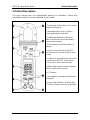
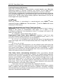
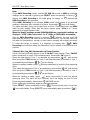
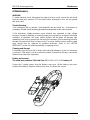
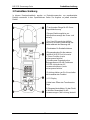
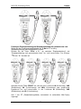
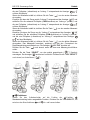
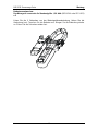
3 Product Description
This user's manual uses only representative model(s) for illustrations. Please refer
specification details for function availability to each model.
1) Transformer Clamp Jaws for AC current
magnetic field pick up
2) Jaw marking lines for ACA (& thus
Power) position error indication
3) Hand/Finger Barrier to indicate the
limits of safe access to the jaws during
current measurements
4) Push-buttons for special functions &
features
5) Input Jack for all functions EXCEPT
non-invasive ACA current (& thus Power)
function
6) Common (Ground reference) Input Jack
for all functions EXCEPT non-invasive
ACA current (& thus Power) function
7) Slide-switch Selector to turn the power
ON/OFF and Select a function
8) LCD display
9) Jaw trigger for opening the transformer
clamp jaws
10) Jaw center Indicators, at where best
ACA (& thus Power) accuracy is specified

MD 9235 Clamp Meter Series Operation
7
4 Operation
CAUTION
Before and after hazardous voltage measurements, test the voltage function on a
known source such as line voltage to determine proper meter functioning.
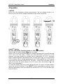
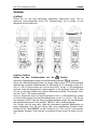
AutoVA
TM
function
Set the slide-switch function-selector to the position.
With no input, the meter displays “ ” when it is ready.
With no ACA current input via the jaws but a voltage signal above the nominal threshold
of DC 2.4V or AC 30V (40Hz ~ 500Hz) up to the rated 600V is present on V-COM
terminals, the meter displays the voltage value in appropriate DC or AC, whichever
larger in peak magnitude. Annunciators “Auto” “dc” and “Auto” “ ” turn on respectively.
On the contrary, with no voltage signal present on V-COM terminals but a ACA current
signal above the nominal threshold of AC 1A (40Hz ~ 500Hz) up to the rated 1000A is
input via the jaws, the meter displays the ACA current value. Annunciators “ ” and
“Auto” turn on accordingly.
The Auto-VA feature stays at the auto-selected function as long as its signal remains
above the specified threshold. Press SELECT button momentarily to manually select
and lock (annunciator “Auto” turns off) thru the functions ACA, ACV, DCV and then goes
back to Auto-VA.

MD 9235 Clamp Meter Series Operation
8
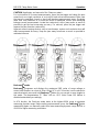
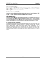
CAUTION (Application and removal of the Clamp-on meter)
For non-invasive ACA current measurements, press the jaw trigger and clamp the jaws
around only one single conductor of a circuit for load current measurement. Make sure
the jaws are completely closed, or else it will introduce measurement errors. Enclosing
more than one conductor of a circuit will result in differential current (like identifying
leakage current) measurement. Locate the conductor(s) at the Jaws center as much as
possible to get the best measuring accuracy. For removal, press the jaw trigger and
remove the jaws from the conductor(s).
Adjacent current-carrying devices such as transformers, motors and conductor wires will
affect measurement accuracy. Keep the jaws away from them as much as possible to
minimize influence.
Peak-rms mode
Peak-rms compares and displays the maximum RMS value of surge voltage or
current with durations as short as 65ms. When ACV or ACA function is auto-selected or
manual-selected, press and hold Peak-rms button for one second or more toggles to
this mode. The annunciators “P-” “Max” turn on. APO (Auto Power Off) feature is
disabled automatically accordingly.
In ACA function, the Peak-rms mode starts at the highest 600A range to maximize
measuring dynamic range. Before making measurement, press the Peak-rms button
momentarily again can manually select thru lower measuring dynamic range 400.0A or
40.00A for higher measuring resolutions.

MD 9235 Clamp Meter Series Operation
9
Line-level Frequency (Hz) function
When ACV or ACA function is auto-selected or manual-selected, press Hz button
momentarily toggles to Line-level Frequency (Hz) function. The Hz trigger level is
determined by the selected function-range from where the Hz function is activated.
In ACA function, activating the Hz function during significant measurements can get the
most appropriate trigger level to avoid electrical noises in most cases. Activating the Hz
function at AC 40.00A range (before making significant measurements) can get the
lowest trigger level (highest sensitivity).
HOLD mode
When any function is auto-selected or manual-selected, press HOLD button
momentarily toggles to Hold mode. The annunciator “ ” turns on. Hold mode freezes
the display for later viewing.
Notes on Displacement Power Factor & Total Power Factor
Introduction: Power is the rate of change of energy with respect to time (in terms of
voltage V and current A). Instantaneous (real) power w = vi where v is the
instantaneous voltage and i the instantaneous current. The average (real) power is the
mean of vi and is given by:
W = ω/2π∫vi dt , over the interval from 0 to 2π/ω
Displacement Power Factor (more traditional): Assuming V and A are pure
sinusoidal waveforms without harmonics (as in most traditional cases), that is, v = V
sinωt and i = I sin (ωt -θ), the expression can be simplified to:
W = 1/2 x V x I x Cosθ where V and I are the peak values, θ is the displacement
power factor angle, and Cosθ is the displacement power factor. Using RMS values, it is
written as:
W = V
rms
x A
rms
x Cosθ
Practically, in such cases without harmonics, θ is also called the phase-shift angle of the
current A to the voltage V. An inductive circuit is said to have a lagging power factor
since current A lags voltage V (phase-shift angle θ and thus Sinθ are both “+”), and a
capacitive circuit is said to have a leading power factor since current A leads voltage V
(phase-shift angle θ and thus Sinθ are both “-”).
Total Power Factor (encountering harmonics): When encountering distorted
waveforms with the presence of harmonics, however, the simplified power expression
should not be used since substituting the above mentioned pure sinusoidal V and A
functions cannot fulfill the actual conditions. Cosine of phase-shift angle (Cosθ), or the
displacement power factor, is no longer the only component constituting the overall
power factor. Harmonics do increase apparent power and thus decrease the overall
power factor. That is, the Total Power Factor is actually affected by both phase-shift
angle and harmonics, and is given by the expression:
Total Power Factor (PF) = Real Power (W) / Apparent Power (VA)
In order to improve overall system power factor, nowadays power-system engineer
needs to address both phase-shift and harmonics problems. Practically, harmonics
should be dealt with (e.g. filtering out) before phase-shift to be corrected (e.g. installing
capacitors in parallel with inductive loads).

MD 9235 Clamp Meter Series Operation
10
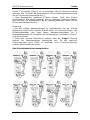
Single-Phase Power & 3-Phase Balanced-Load Power functions
Set the slide-switch function-selector to the “3~Bal ● 1~” Power position.
Default at last selected function.
Press “3~Bal ● 1~” button momentarily to toggle between “Single-Phase” and “3-Phase
Balanced Load” Power functions. Annunciators “ ” and “3~” turn on respectively.
●Press SELECT button momentarily selects between W (real power), VAR (reactive
power), VA (apparent power) & kWHr (real-time readings or stored result) functions. In
W (real power), VAR (reactive power), or VA (apparent power) function:
1. PF (Total Power Factor) is displayed automatically in the secondary mini display.
2. Annunciator “A-lags-V” turns on to indicate an inductive circuit is being measured.
That is, the Current waveform is lagging the Voltage waveform, and the phase-shift
angle θ is “+”.

MD 9235 Clamp Meter Series Operation
11
3. On the contrary, together with significant PF values, WITHOUT “A-lags-V” being
turned on indicates that a capacitive circuit is being measured. That is, the Current
waveform is leading the Voltage waveform, and the phase-shift angle θ is “-”.
Note:
1. Under proper measurement setups for load circuits, the W (real power) readings are
always positive. Negative W readings indicate reversed clamp-on jaws direction or test
leads polarities, or even incorrect voltage lines are being measured as in 3-phase
measurement setups. Correct them for proper “A-lags-V” indications.
2. When encountering largely distorted waveforms, “A-lags-V” detection might be
affected due to the influence of harmonics. It is recommended to manage (e.g. filter out)
harmonics problems before measuring/dealing with phase-shift problems.

MD 9235 Clamp Meter Series Operation
12
kWHr (kilo-Watt-Hour) Recording function
Set the slide-switch function-selector to the “3~Bal ● 1~” Power position. Setup power
measurements as mentioned in the previous “Single-Phase Power & 3-Phase
Balanced-Load Power functions” section
To start (“ ”) kWHr Recording, press “3~Bal ● 1~” and “HOLD” buttons at the
same time. Annunciator “ ” turns on & flashes. kWHr accumulated time (in Hour) is
displayed automatically in the secondary mini display.
To pause (“ ”), press “HOLD” button momentarily. Annunciator “ ” stops flashing
and is always on.
To continue (“ ”), press the “HOLD” button momentarily again. Annunciator “ ”
resumes flashing.
To stop (“ ”), press the “3~Bal ● 1~” and “HOLD” buttons at the same time again.
Annunciator “ ” turns off. The kWHr Recording result is then displayed on the LCD
for immediate viewing. Annunciator “ ” turns on & flashes.
When the low battery annunciator “ ” turns on, the meter will stop (“ ”) kWHr
recording session automatically and display kWHr Recording result as in above.

MD 9235 Clamp Meter Series Operation
13
Note:
During kWHr Recording session, real-time W, VAR, VA as well as kWHr accumulated
readings can be selected by pressing the SELECT button momentarily. A flashing “ ”
denotes that kWHr Recording is still under-going. An always on “ ” denotes that
kWHr Recording is being paused.
When kWHr Recording is not activated, kWHr stored result instead of accumulated
readings is displayed when selected as in above. Annunciator “ ” turns on & flashes.
The meter separately stores one Single-Phase and one 3-Phase-Balanced-Load kWHr
result for later viewing. When they are being viewed, press “3~Bal ● 1~” button
momentarily to toggle between them.
When the display readings exceed 9999kWHr/999hours, exponential readings are
displayed. “2.3E4” kWHr represents 2.3 x 10
4
kWHr, or 23000 kWHr for example,.
After the kWHr Recording session is stopped (“ ”) properly, the new result will
supersede the previous one stored in the non-volatile memory. You can then switch off
the meter for transportation, storage, or even battery changing with memory remained.
To avoid mis-storage to memory, it is important to properly stop (“ ”) kWHr
Recording session before sliding the slide-switch function-selector to any other function
positions.
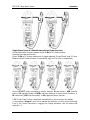
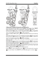
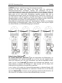
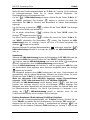
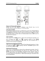
3-Phase 3-Wire (3 3W) Unbalanced-Load Power Function
Set the slide-switch function-selector to the “3~Un-Bal” Power position. Press “3W●4W”
button momentarily to select 3-Wire measurements. Annunciator “3W” turns on.
Clamp the jaws around “Line 1” as reminded by annunciators “ L1”, and connect
Black test probe (COM terminal) to “Line 3” and Red test probe (+ terminal) to “Line 1”
as reminded by annunciators “ ” on mini-display.
When the reading is stable, press “ ” button momentarily to enter the first measuring
value.
Then clamp the jaws around “Line 2” as reminded by annunciators “ L2”, and connect
Black test probe (COM terminal) to “Line 3” and Red test probe (+ terminal) to “Line 2”
as reminded by annunciators “ ” on mini-display.
When the reading is stable, press “ ” button momentarily to enter the second
measuring value. The meter will then calculate, store and display the total 3-Phase
Power result automatically. Annunciators “ L1 L2 L3” turn on.
Press “ ” button momentarily again for new measurements.
Press “SELECT” button momentarily to view (“ ”) the last stored result. Annunciator
“ ” turns on & flashes. Press “SELECT” button momentarily again to continue (“ ”).

MD 9235 Clamp Meter Series Operation
14
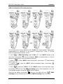
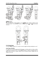
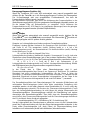
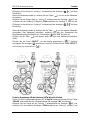
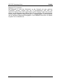
3-Phase 4-Wire (3 4W) Unbalanced-Load Power function
Set the slide-switch function-selector to the “3~Un-Bal” Power position. Press “3W●4W”
button momentarily to select 4-Wire measurements. Annunciator “4W” turns on.
Clamp the jaws around “Line 1” as reminded by annunciators “ L1”, and connect
Black test probe (COM terminal) to “Line n (neutral)” and Red test probe (+ terminal) to
“Line 1” as reminded by annunciators “ ” on mini-display.
When the reading is stable, press “ ” button momentarily to enter the first measuring
value.
Then clamp the jaws around “Line 2” as reminded by annunciators “ L2”, and connect
Black test probe (COM terminal) to “Line n (neutral)” and Red test probe (+ terminal) to
“Line 2” as reminded by annunciators “ ” on mini-display.
When the reading is stable, press “ ” button momentarily to enter the second
measuring value.
Then clamp the jaws around “Line 3” as reminded by annunciators “ L3”, and connect
Black test probe (COM terminal) to “Line n (neutral)” and Red test probe (+ terminal) to
“Line 3” as reminded by annunciators “ ” on mini-display.
When the reading is stable, press “ ” button momentarily to enter the third measuring
value. The meter will then calculate, store and display the total 3-Phase Power result
automatically. Annunciators “ L1 L2 L3” turn on.
Press “ ” button momentarily again for new measurements.
Press “SELECT” button momentarily to view (“ ”) the last stored result. Annunciator
“ ” turns on & flashes. Press “SELECT” button momentarily again to continue (“ ”).

MD 9235 Clamp Meter Series Operation
15
/ functions
Set the slide-switch function-selector to the / function position. Default at last
selected function. Press SELECT button to toggle between and measurement
functions.
Backlighted display
Press the SELECT button for 1 second or more to toggle the display backlight on or off.
Auto Power Off (APO)
The meter turns off after approximately 30 minutes of neither switch nor button activity.
To wake up the meter from APO, press SELECT button or slide the function-selector to
OFF position and back on again. Always turn the function-selector to OFF when the
meter is not in use.

MD 9235 Clamp Meter Series Operation
16
Auto Power Off Quick Test
Press-and-hold the 3W.4W button while powering the meter on. The LCD displays
“ ” & “ ” to confirm activation right after the 3W.4W button is released. Quick test
APO timing is 10 seconds after such activation.
Disabling Auto-Power-Off (APO)
Press-and-hold the HOLD button while powering the meter on. The LCD displays “ ”
& “ ” to confirm activation right after the HOLD button is released.
Line Frequency setup
Press-and-hold the Hz button while powering the meter on. LCD displays the last 50Hz
or 60 Hz setup. Press SELECT button momentarily to select 50Hz or 60Hz to cope with
your local line frequency. Press Hz button for one second to store your selection and
resume measurements. Incorrect line frequency setup will introduce errors to THD%.
PC computer interface capabilities
The instrument equips with an optical isolated data output port at the bottom case near
the battery compartment. Optional purchase PC interface kit AMD 9240 (including
Optical Adapter Back, Cable, USB-to-Serial adaptor & Bs software/driver CD) is
required to connect the meter to PC computer USB port. The Data Recording System
software equips with a digital meter, an analog meter, a comparator meter, and a Data
Graphical recorder. Refer to the README file comes with the interface kit for further
details.

MD 9235 Clamp Meter Series Specifications
17
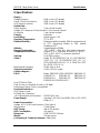
5 Specifications
Display :
Voltage functions: 6000 counts LCD display
Power, Ohm & Hz functions: 9999 counts LCD display
ACA clamp-on function: 4000 counts LCD display
Update Rate :
Power function: 2 per second nominal
Voltage, ACA clamp-on & Ohm functions: 2 per second nominal
Hz function: 1 per second nominal
Polarity : Automatic
Low Battery : Below approx. 2.4V
Operating Temperature : 0
o
C to 40
o
C
Relative Humidity : Maximum relative humidity 80% for emperature up
to 31
o
C decreasing linearly to 50% relative
humidity at 40
o
C
Altitude : Operating below 2000m
Storage Temperature : -20
o
C to 60
o
C, < 80% R.H. (with battery removed)
Temperature Coefficient : nominal 0.15 x (specified accuracy)/
o
C @(0
o
C -
18
o
C or 28
o
C -40
o
C), or otherwise specified
Sensing : True RMS sensing
Safety : Meets IEC/UL/EN61010-1 Ed. 3.0, IEC/EN61010-
2-032 Ed. 3.0, IEC/EN61010-2-033 Ed. 1.0,
IEC/UL/EN61010-031 Ed. 1.1 & CAN/CSA-C22.2
No. 61010-1-12 Ed. 3.0
Measurement Category: III 600 Volts ac & dc
Transient protection: 6.5kV (1.2/50s surge)
Pollution degree: 2
E.M.C.: Meets EN61326-1:2006 (EN55022, EN61000-3-2,
EN61000-3-3, EN61000-4-2, EN61000-4-3,
EN61000-4-4, EN61000-4-5, EN61000-4-6,
EN61000-4-8, EN61000-4-11)
In an RF field of 3V/m:
Total Accuracy = Specified Accuracy + 50 digits
Performance above 3V/m is not specified
Overload Protections :
ACA Clamp-on jaws :
AC 600A rms continuous
+ & COM terminals (all functions) : 600VDC/VAC rms
Power Supply: standard 1.5V AAA Size (NEDA 24A or IEC LR03)
battery X 2
Power Consumption :
Voltage, ACA, Hz & Power functions: 11mA typical
Ohm function: 5.5mA typical
APO Timing : Idle for 30 minutes
APO Consumption : 4A typical
Dimension : L189 X W78 X H40 mm
Weight : 192 gm approx
Jaw opening & Conductor diameter : 26mm max

MD 9235 Clamp Meter Series Specifications
18
Special features : Backlighted display; AutoVA
TM
(Auto Selection on ACV, DCV or
ACA functions); selectable Power parameters of W, VAR & VA with Total Power Factor
in dual-display; kWHr Recording; Display Hold; PEAK-rms HOLD; PC-Comm computer
interface capabilities
Accessories : Test leads (pair), batteries installed, user's manual & soft carrying pouch
Optional accessories : PC interface kit AMD 9240 (including Optical Adapter Back,
Cable, USB-to-Serial adaptor & Bs software/driver CD)
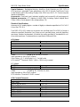
Electrical Specifications
Accuracy is ±(% reading digits + number of digits) or otherwise specified, at 23
o
C ±5
o
C
& less than 75% R.H.
True RMS ACV & ACA clamp-on accuracies are specified from 0% to 100% of range or
otherwise specified. Maximum Crest Factor are as specified below, and with frequency
spectrums, besides fundamentals, fall within the meter specified AC bandwidth for non-
sinusoidal waveforms. Fundamentals are specified at 50Hz and 60Hz.
AC Voltage
RANGE
Accuracy
50Hz / 60Hz
600.0V
0.5% + 5d
45Hz ~ 500Hz
600.0V
1.5% + 5d
500Hz ~ 3.1kHz
600.0V
2.5% + 5d
CMRR : >60dB @ DC to 60Hz, Rs=1k
Input Impedance: 2M, 30pF nominal
Crest Factor: < 2 : 1 at full scale & < 4 : 1 at half scale
ACV AutoVA
TM
Threshold: 30VAC (40Hz ~ 500Hz only) nominal
DC Voltage
RANGE
Accuracy
600.0V
0.5% + 5d
NMRR : >50dB @ 50/60Hz
CMRR : >120dB @ DC, 50/60Hz, Rs=1k
Input Impedance: 2M, 30pF nominal
DCV AutoVA
TM
Threshold: 2.4VDC nominal
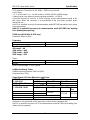
ACA Current (Clamp-on)
RANGE
Accuracy
1) 2)
50Hz / 60Hz
40.00A, 400.0A, 600A
1.0% + 5d
45Hz ~500Hz
40.00A, 400.0A
2.0% + 5d
600A
2.5% + 5d
500Hz ~ 3.1kHz
40.00A, 400.0A
2.5% + 5d
600A
3.0% + 5d

MD 9235 Clamp Meter Series Specifications
19
ACA AutoVA
TM
Threshold: 1A AC (40Hz ~ 500Hz only) nominal
Crest Factor:
< 3 : 1 at full scale & < 6 : 1 at half scale for 40.00A, 400.0A & 600A ranges
1)
Induced error from adjacent current-carrying conductor: < 0.06A/A
2)
Specified accuracy is from 1% to 100% of range and for measurements made at the
jaw center. When the conductor is not positioned at the jaw center, position errors
introduced are:
Add 1% to specified accuracy for measurements made WITHIN jaw marking lines (away
from jaw opening)
Add 4% to specified accuracy for measurements made BEYOND jaw marking
lines (toward jaws opening)
PEAK-rms HOLD (ACA & ACV only)
Response: 65ms to >90%
Frequency
RANGE
Accuracy
5Hz ~ 500Hz
0.5%+4d
Sensitivity (Sine RMS)
40A range: > 4A
400A range: > 40A
600A range: > 400A
600V range: > 30V
Ohms
RANGE
Accuracy
999.9
1.0% + 6d
Open Circuit Voltage : 0.4VDC typical
Audible Continuity Tester
Audible threshold: between 10 and 300.
Response time: 250s
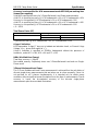
Single-Phase & 3-Phase Balanced-Load Power
RANGE
5)
0 ~ 600.0kVA
Accuracy
1) 2) 3)
F ~ 10th
11th ~ 45th
46th ~ 51st
@ PF = 0.99 ~ 0.1
2.0%+6d
3.5%+6d
5.5%+6d
RANGE
5)
0 ~ 600.0kW / kVAR
Accuracy
1) 2) 4)
F ~ 10th
11th ~ 25th
26th ~ 45th
46th ~
51st
@ PF = 0.98 ~ 0.70
2.0%+6d
3.5%+6d
4.5%+6d
10%+6d
@ PF = 0.70 ~ 0.50
3.0%+6d
@ PF = 0.50 ~ 0.30
4.5%+6d
@ PF = 0.30 ~ 0.20
10%+6d
15%+6d
1)
Specified accuracy is for ACA clamp measurement at the center of jaws. When the
conductor is not positioned at the jaw center, position errors introduced are:
Add 1% to specified accuracy for ACA measurements made WITHIN jaw marking lines
(away from jaw opening)

MD 9235 Clamp Meter Series Specifications
20
Accuracy is not specified for ACA measurement made BEYOND jaw marking lines
(toward jaws opening)
2)
Add 4d to specified accuracy for 3-Phase Balanced-Load Power measurements.
3)
Add 1% to specified accuracy @ ACA fundamental < 6A or ACV fundamental < 90V.
Accuracy is not specified @ ACA fundamental < 1A or ACV fundamental < 30V
4)
Add 1% to specified accuracy @ ACA fundamental < 6A or ACV fundamental < 90V.
Accuracy is not specified @ ACA fundamental < 2A or ACV fundamental < 50V
5)
0 ~ 360.0
Total Power Factor (PF)
RANGE
Accuracy
1)
0.10 ~ 0.99
F ~ 21st
22nd ~ 51st
3d
5d
1)
Specified accuracy @ ACA fundamental > 2A ; ACV fundamental > 50V
A-lags-V Indication:
LCD annunciator “A-lags-V” turns on to indicate an inductive circuit, or Current A lags
Voltage V (i.e., phase-shift angleθ is “+”).
A-lags-V Indication is specified at 50/60Hz fundamental without the presence of
harmonics, and at ACV > 90V, ACA > 9A and PF < 0.95
kWHr (kilo-Watt-Hour Energy)
Time base accuracy: < 30ppm
Non-volatile memory: Separately stores one 3-Phase-Balanced-Load and one Single-
Phase result
3-Phase Unbalanced-Load Power
This 3-Phase Unbalanced-Load Power measurement is achieved thru the calculation of
discrete single-phase measurements that are taken one at a time manually. Since it is
not real-time on all 3 phases simultaneously, it is intended only for stable power
conditions without significant power fluctuations over the time of measurements. Result
accuracy is hence the accumulated accuracy of the discrete single-phase
measurements plus the associated fluctuations.
Seite wird geladen ...
Seite wird geladen ...
Seite wird geladen ...
Seite wird geladen ...
Seite wird geladen ...
Seite wird geladen ...
Seite wird geladen ...
Seite wird geladen ...
Seite wird geladen ...
Seite wird geladen ...
Seite wird geladen ...
Seite wird geladen ...
Seite wird geladen ...
Seite wird geladen ...
Seite wird geladen ...
Seite wird geladen ...
Seite wird geladen ...
Seite wird geladen ...
Seite wird geladen ...
Seite wird geladen ...
Seite wird geladen ...
Seite wird geladen ...
-
 1
1
-
 2
2
-
 3
3
-
 4
4
-
 5
5
-
 6
6
-
 7
7
-
 8
8
-
 9
9
-
 10
10
-
 11
11
-
 12
12
-
 13
13
-
 14
14
-
 15
15
-
 16
16
-
 17
17
-
 18
18
-
 19
19
-
 20
20
-
 21
21
-
 22
22
-
 23
23
-
 24
24
-
 25
25
-
 26
26
-
 27
27
-
 28
28
-
 29
29
-
 30
30
-
 31
31
-
 32
32
-
 33
33
-
 34
34
-
 35
35
-
 36
36
-
 37
37
-
 38
38
-
 39
39
-
 40
40
-
 41
41
-
 42
42


METREL MD 9235 Benutzerhandbuch
- Kategorie
- Messen, Testen
- Typ
- Benutzerhandbuch
in anderen Sprachen
- English: METREL MD 9235 User manual
Verwandte Artikel
-
 METREL MD 9240 Benutzerhandbuch
-
 METREL MD 9225 Industrial TRMS AC-DC Current Clamp Meter Benutzerhandbuch
-
 METREL MD 9225 Benutzerhandbuch
-
 METREL MD 9210 Benutzerhandbuch
-
 METREL MD 9225 Industrial TRMS AC-DC Current Clamp Meter Benutzerhandbuch
-
 METREL MD 9220 Benutzerhandbuch
-
METREL MD 9250 Benutzerhandbuch
-
 METREL MD 9272 Benutzerhandbuch
-
 METREL MD 9272 Benutzerhandbuch
-
 METREL MD 9272 Benutzerhandbuch


Andere Dokumente
-
Amprobe ACD-30P & ACD-41PQ Clamp-On Power Meters Benutzerhandbuch
-
PeakTech P2510 Bedienungsanleitung
-
Extech Instruments PQ2071 Benutzerhandbuch
-
Fluke I310S Bedienungsanleitung
-
-
 PEAK-System PCAN-MiniDisplay Bedienungsanleitung
-
Samlexpower PST-300S-12E Bedienungsanleitung
-
Extech Instruments 382252 Benutzerhandbuch
-
 PEAK-System PCAN-MiniDisplay Bedienungsanleitung
-

