
BC-HM EI.95.N7.66 © Danfoss 7/98 1
Instructions
AMB 160
082R9075
082R9075
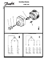
3 - Point/3-punktowa
Blå Brun Sort Sort Sort
Blue Brown Black Black Black
Blau Braun Schwarz Schwarz Schwarz
Bleu Brun Noir Noir Noir
Azul Marr¢n Negro Negro Negro
Blå Brun Svart Svart Svart
Blauw Bruin Zwart Zwart Zwart
Sininen Ruskea Musta Musta Musta
Niebieski Br¹zowy Czarny Czarny Czarny
Blå Brun Sort
Blue Brown Black
Blau Braun Schwarz
Bleu Brun Noir
Azul Marr¢n Negro
Blå Brun Svart
Blauw Bruin Zwart
Sininen Ruskea Musta
Niebieski Br¹zowy Czarny
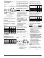
Fig. 1
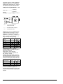
Fig. 2 Fig. 3
3 - Point/3-punktowa

2 EI.95.N7.66 © Danfoss 7/98 BC-HM
The 24 V AC/DC supply voltage is
connected to the wires which are marked
1 and 2. The following control signals
can be used: 0 - 10 VDC, 2 - 10 VDC,
0 - 5 VDC, 1 - 5 VDC, 0 - 20 mA and
4 - 20 mA (cf. the table below).
Factory set at 0 - 10 VDC.
The control signal (Y) is connected to
the brown wire. The following settings
are available for the speed of the
actuator: 60 sec., 90 sec., 120 sec. The
actuator is factory set at 120 sec.
The closed position "clockwise" CW can
be changed by removing the jumper
switch "DIR". The closed position will
then be counterclockwise CCW. The
jumper switches are placed on the printed
circuit board under the actuator's cover.
DANSK
1. Indstil ventilen til midt på skalaen og
fjern ventilens håndhjul uden at
ændre spindlens position.
2. Placér akselkoblingen ➊ over
spindlen uden at ændre spindlens
position.
3. Indsæt skruen ➋ i øverste højre
hjørne på ventilens dækplade.
4. Montér motoren på ventilen og indsæt
skruen ➌ i midten af motorens
håndhjul.
5. Vælg den side på skalaen ➍, som
passer til ventilens reguleringsretning,
og sæt den fast i dækslet ➎ på
håndhjulet. Tryk dernæst dækslet fast
på håndhjulet.
6. Foretag el-tilslutning som vist i Fig. 2.
Foran motoren bør der monteres en
fler-polet afbryder i den faste
installation.
7. Ved manuel betjening: Tryk og drej
håndhjulet i den ønskede retning.
ADVARSEL: Afbryd strømmen før
motordækslet fjernes!
Motor med hjælpekontakt:
El-tilslutningen skal være som vist i Fig. 3.
Indstilling af kontaktens position sker ved
at fjerne motordækslet og dreje den
hvide kamskive til den ønskede position.
AMB 160, 0 - 10V El-tilslutning
___________ 1 (sort)
24 V AC/DC
___________ 2 (sort)
Styresignal Y ______ Brun (0 - 10 VDC)
Forsyningsspændingen er 24 V AC/DC,
ledning mrk 1. og 2.
Der kan anvendes flg. styresignaler
0 - 10 VDC, 2 - 10 VDC, 0 - 5 VDC,
1 - 5 VDC, 0 - 20 mA og 4 - 20 mA
(se skema SIGNAL)
Signal
Jumper
DCO
0 - 5 V
1 - 5 V ■
0 - 10 V ■
2 - 10 V ■■
0 - 20 mA ■
4 - 20 mA ■■
Lukkeposition "med uret" CW kan
ændres ved at fjerne jumper "DIR".
Lukkeposition er da "mod uret" CCW.
Jumperne er placeret på printkortet under
dækslet.
DEUTSCH
Jumper
Signal D C O
0 - 5 V
1 - 5 V ■
0 - 10 V ■
2 - 10 V ■■
0 - 20 mA ■
4 - 20 mA ■■
Fabriksindstilling 0 - 10 VDC.
Styresignal (Y) tilsluttes den brune
ledning.
Motorhastigheden kan indstilles til flg.
værdier 60 sec., 90 sec., og 120 sec.
Fabriksindstilling: 120 sec.
Jumper
Løbetid
60 S 90 S 120 S
60 S ■
90 S ■
120 S ■
ENGLISH
1. Set the valve in the mid-position of the
scale plate and remove the knob/
handle without changing the position
of the spindle.
2. Place the sleeve ➊ on the spindle.
3. Fit the screw ➋ in the upper right
hand corner of the valve cover plate.
4. Fit the actuator to the valve and
secure with the central screw ➌ in the
centre of the knob.
5. Choose the side of the red/blue
scale ➍ according to the control
direction of the valve and fit it within
the cover ➎ on the knob. Finally press
the cover on to the knob.
6. Connect the wiring as shown in Fig. 2.
The actuator should be preceded by a
multi-pole contact breaker in the fixed
installation.
7. For manual operation: Press and turn
the knob in desired direction.
WARNING: Do not remove the
actuator cover without first
disconnecting the supply!
Actuator with auxillary switch
The wiring should be connected as shown
in Fig. 3. To set the switch position,
remove the actuator cover and turn the
white cam sleeve to the desired position.
Wiring AMB 160, 0 - 10V
___________ 1 (black)
24 V AC/DC
___________ 2 (black)
Control signal Y ___ Brown (0 -10 VDC)
Jumper
Running time
60 S 90 S 120 S
60 S ■
90 S ■
120 S ■
1. Mischer auf die Mitte der Skala ein-
stellen. Stellknopf bzw. Handhebel
entfernen.
2. Mitnehmerhülse ➊ auf der Achse
festdrücken.
3. Schraube ➋ oben rechts am
Mischerdeckel montieren.
4. Antrieb auf die Mischerachse setzen
und mit Schraube ➌ montieren.
5. Die Seite der rot/blauen Skala ➍
wählen, die der Öffnungsrichtung des
Mischers entspricht. Skala und Deckel
➎ auf dem Antriebknopf festdrücken.
6. Verdrahtung des Antriebs gemäß
Anschlußplan Nr. 2. Dem Antrieb soll
in der festen Installation ein mehr-
poliger Schalter vorgeschaltet werden.
7. Handbedienung des Mischers:
Antriebknopf nach unten drücken und
in die gewünschte Richtung drehen.
ACHTUNG: Antriebgehäuse nur
entfernen, wenn der Strom
abgeschaltet ist!
Antrieb mit zusätzlichem Mikroschalter
Verdrahtung gemäß Anschlußplan Fig. 3.
Um die Schaltposition einzustellen, wird
das Antriebgehäuse entfernt und die
weiße Nockenscheibe in die gewünschte
Position gedreht.
Ust = 0 - 10 V d.c./2-10V d.c.
/0-20 mA/4-20 mA
Y = Brun/Brown/Braun
1,2 = Sort/Black/Schwarz
Ust = 0 - 10 V d.c./2-10V d.c.
/0-20 mA/4-20 mA
Y = Brun/Brown/Braun
1,2 = Sort/Black/Schwarz

BC-HM EI.95.N7.66 © Danfoss 7/98 3
An den Klemmen 1 und 2 liegt die Ver-
sorgungsspannung von 24 V AC. An den
Klemmen Y und M ist das Steuersignal
anzuschließen.
Die folgenden Steuersignale können ver-
wendet werden: 0 - 10 VDC, 2 - 10 VDC,
0 - 5 VDC, 1 - 5 VDC, 0 - 20 mA und
4 - 20 mA (Siehe Schema Signal).
Werkseitig ist der Antrieb auf 0 - 10 VDC
eingestellt. Das Steuersignal (Y) wird an
die braune Leitung angeschlossen.
Die Geschwindigkeit des Antriebs kann
auf die folgenden Geschwindigkeiten
eingestellt werden: 60 sec., 90 sec., und
120 sec. Werkseitig ist der Antrieb auf
120 sec. eingestellt.
Die Endposition "im Uhrzeigersinn" wird
geändert durch Entfernen des Kurz-
schlußbügels "DIR". Die Endposition ist
dann gegen den Uhrzeigersinn. Der
Kurzschlußbügel befindet sich auf der
Printplatte unter der Antriebabdeckung.
Kurzschlußbügel
Laufzeit
60 S 90 S 120 S
60 Sek ■
90 Sek ■
120 Sek ■
FRANÇAIS
1. Régler la vanne en position 5 et
démonter le bouton de réglage sans
changer la position de l’axe.
2. Placer l’accouplement ➊ sur l’axe de
la vanne.
3. Fixer la vis ➋ sur la partie supérieure
droite de la vanne.
4. Mettre la commande manuelle du
moteur en position blocage (on ne doit
pas pouvoir tourner le bouton dans un
sens ou dans l’autre). Placer le
moteur sur l’axe de la vanne et faire
correspondre le taquet de blocage
avec la vis ➋. Serrer l’ensemble
moteur et vanne à l’aide de la vis ➌.
5. Placer l’étiquette ➍ du côté rouge ou
bleu selon la fonction de contrôle
choisie et presser le cache ➎ sur le
bouton.
6. Réaliser les connections électriques
suivant la fig. 2.- Phase sur fil brun : le
moteur tourne dans le sens des
aiguilles d’une montre - Phase sur fil
noir : le moteur tourne dans le sens
inverse des aiguilles d’une montre. Un
interrupteur doit être placé en amont
de l’installation avant la pose du
moteur.
7. Commande manuelle : appuyer sur le
bouton et tourner dans le sens désiré.
ATTENTION: Ne pas démonter le
moteur sous tension.
Moteur avec contact auxiliaire
Réaliser les connections électriques
suivant la fig. 3. Pour régler la position
du contact, démonter le capot du moteur
et tourner la came blanche jusqu’à la
position désirée.
Raccordement électrique
AMB 160, 0 - 10V
———— 1 (noir)
24V c.a./c.c.
———— 2 (noir)
Signal de
commande Y———— brun (0 - 10V c.c.)
La tension d’alimentation 24 V c.a./c.c.
est raccordée aux fils 1 et 2. Les
tensions de commande suivantes
peuvent être utilisées: 0 - 10 V c.c., 2 -
10 V c.c., 0 - 5 V c.c., 1 - 5 V c.c., = - 20
mA et 4 - 20 mA (voir tableau ci-après).
Le réglage d’usine est à 0 - 10 V. c.c.
Le signal de commande Y est raccordé
au fil brun.
Différents réglages de vitesse de rotation
du moteur sont disponibles: 60 sec.,
90 sec., 120 sec. Le réglage d’usine est
à 120 sec.
La position fermée quand le moteur
tourne dans le sens des aiguilles d’une
montre (CW) peut être changée en enle-
vant le cavalier DIR. La position fermée
sera alors atteinte quand le moteur aura
tourné dans les sens inverse des aiguilles
d’une montre (CCW).
Les cavaliers se trouvent ser le circuit
sous le couvercle du moteur.
Cavalier
Commande
DCO
0 - 5 V
1 - 5 V ■
0 - 10 V ■
2 - 10 V ■■
0 - 20 mA ■
4 - 20 mA ■■
Temps de Cavalier
rotation
60 S 90 S 120 S
60 S ■
90 S ■
120 S ■
ESPAÑOL
1. Situe la válvula en la posición inter-
media de la escala y quite el mando
sin cambiar la posición del eje.
2. Situar la pieza ➊ en el eje.
3. Colocar el tornillo ➋ en la esquina
superior derecha de la carcasa de la
válvula.
4. Unir el motor a la válvula y asegurar
con el tornillo ➌ en el centro del
mando.
5. Seleccione el lado rojo ó azul ➍ de
acuerdo a la dirección de control de la
válvula y coloque la carcasa ➎
encima del mando. Finalmente pre-
sione la carcasa encima del mando.
6. Conecte según muestra la fig. 2. El
motor debe actuarse mediante un
interruptor multipolar.
7. Para operar manualmente, presione y
gire el mando en la posición deseada.
ADVERTENCIA: No desmonte la car-
casa del motor sin haber desconectado
primero la corriente eléctrica.
Motor con contacto auxiliar
El conexionado debe ser realizado como
muestra la fig. 3. Para ajustar la posición
del contacto, quite la carcasa del motor y
gire la leva blanca a la posición deseada.
Elektrischer Anschluß 160, 0 - 10 V
________ 1 (schwarz)
24 V AC
________ 2 (schwarz)
Steuersignal Y______ Braun 0 -10VDC
Kurzschlußbügel
Signal
DCO
0 - 5 V
1 - 5 V ■
0 - 10 V ■
2 - 10 V ■■
0 - 20 mA ■
4 - 20 mA ■■
Ust = 0 - 10 V d.c./2-10V d.c.
/0-20 mA/4-20 mA
Y = Brun/Brown/Braun
1,2 = Sort/Black/Schwarz
Ust = 0 - 10 V d.c./2-10V d.c.
/0-20 mA/4-20 mA
Y = Brun/Brown/Braun
1,2 = Sort/Black/Schwarz
Seite wird geladen ...
Seite wird geladen ...
Seite wird geladen ...
Seite wird geladen ...
Seite wird geladen ...
-
 1
1
-
 2
2
-
 3
3
-
 4
4
-
 5
5
-
 6
6
-
 7
7
-
 8
8


in anderen Sprachen
- English: Danfoss AMB 160 Operating instructions
- français: Danfoss AMB 160 Mode d'emploi
- español: Danfoss AMB 160 Instrucciones de operación
- Nederlands: Danfoss AMB 160 Handleiding
- dansk: Danfoss AMB 160 Betjeningsvejledning
- polski: Danfoss AMB 160 Instrukcja obsługi
- svenska: Danfoss AMB 160 Bruksanvisningar
- suomi: Danfoss AMB 160 Käyttö ohjeet
Verwandte Artikel
-
Danfoss Calendar module Bedienungsanleitung
-
-
-
-
-
-
-
-