
Montage- und Betriebsanleitung
Mounting and operating instructions
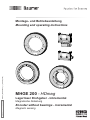
MHGE 200 - HDmag
Lagerloser Drehgeber - inkremental
Magnetische Abtastung
Encoder without bearings - incremental
Magnetic sensing
MB201T1 - 11068569
Baumer_MHGE200-T1_II_DE-EN (19A3)

Baumer_MHGE200-T1_II_DE-EN (19A3)
MB201T1 - 11068569
Inhaltsverzeichnis
Inhaltsverzeichnis
1 Allgemeine Hinweise ................................................................................................................................................ 1
2 Sicherheitshinweise
.................................................................................................................................................3
3 Vorbereitung
..................................................................................................................................................................5
3.1 Lieferumfang
..................................................................................................................................................... 5
3.1.1 Geberrad je nach Version
......................................................................................................................5
3.1.2 Abtastkopf
....................................................................................................................................................... 7
3.2 Zur Montage erforderlich (nicht im Lieferumfang enthalten)
...................................................8
3.3 Zur Demontage erforderlich (nicht im Lieferumfang enthalten)
............................................. 8
3.4 Erforderliches Werkzeug (nicht im Lieferumfang enthalten)
...................................................8
4 Montage
.............................................................................................................................................................................9
4.1 Montage des Geberrades
.......................................................................................................................... 9
4.1.1 Schraubmontage (MHGE 200 xx G)
.................................................................................................9
4.1.2 Spannsatzmontage (MHGE 200 xx Z, MHGE 200 xx Y)
......................................................9
4.1.3 Heißschrumpfmontage (MHGE 200 xx G)
................................................................................. 10
4.1.4 Klemmringmontage (MHGE 200 xx K)
......................................................................................... 10
4.2 Montage des Abtastkopfes
......................................................................................................................11
5 Abmessungen
............................................................................................................................................................ 12
5.1 Schraubmontage oder Heißschrumpfmontage (MHGE 200 xx G)
................................... 12
5.2 Spannsatzmontage (MHGE 200 xx Z, MHGE 200 xx Y)
....................................................... 13
5.3 Klemmringmontage (MHGE 200 xx K)
............................................................................................ 14
6 Elektrischer Anschluss
....................................................................................................................................... 15
6.1 Beschreibung der Anschlüsse
.............................................................................................................. 15
6.2 Ausgangssignale
......................................................................................................................................... 16
6.3 Abtastkopf mit Flanschdose
...................................................................................................................17
6.3.1 Kabelanschluss Rundsteckverbinder - Schritt 1
......................................................................17
6.3.2 Kabelanschluss Rundsteckverbinder - Schritt 2
..................................................................... 18
6.3.3 Stiftbelegung Flanschdose
................................................................................................................. 18
6.4 Abtastkopf mit Klemmenkasten
........................................................................................................... 19
6.4.1 Kabelanschluss Anschlussplatine
................................................................................................... 19
6.4.2 Anschlussbelegung Anschlussplatine
.......................................................................................... 20
6.5 Sensorkabel HEK 8 (Zubehör)
............................................................................................................. 20
7 Demontage
................................................................................................................................................................... 21
7.1 Demontage des Abtastkopfes
.............................................................................................................. 21
7.2 Demontage des Geberrades
................................................................................................................. 22
7.2.1 Schraubmontage (MHGE 200 xx G)
.............................................................................................. 22
7.2.2 Spannsatzmontage (MHGE 200 xx Z, MHGE 200 xx Y)
................................................... 22
7.2.3 Heißschrumpfmontage (MHGE 200 xx G)
................................................................................. 23
7.2.4 Klemmringmontage (MHGE 200 xx K)
......................................................................................... 23
8 Zubehör
.......................................................................................................................................................................... 24
9 Technische Daten
.................................................................................................................................................... 25
9.1 Technische Daten - elektrisch
.............................................................................................................. 25
9.2 Technische Daten - elektrisch (Rechteck)
..................................................................................... 25
9.3 Technische Daten - elektrisch (SinCos)
.......................................................................................... 25
9.4 Technische Daten - mechanisch
......................................................................................................... 26

MB201T1 - 11068569
Baumer_MHGE200-T1_II_DE-EN (19A3)
Table of contents
Table of contents
1 General notes ................................................................................................................................................................ 2
2 Security indications
.................................................................................................................................................. 4
3 Preparation
.....................................................................................................................................................................5
3.1 Scope of delivery
............................................................................................................................................ 5
3.1.1 Encoder wheel depending on version
.............................................................................................. 5
3.1.2 Sensor head
..................................................................................................................................................7
3.2 Required for mounting (not included in scope of delivery)
....................................................... 8
3.3 Required for dismounting (not included in scope of delivery)
.................................................8
3.4 Required tools (not included in scope of delivery)
........................................................................ 8
4 Mounting
........................................................................................................................................................................... 9
4.1 Mounting the encoder wheel
....................................................................................................................9
4.1.1 Screw mounting (MHGE 200 xx G)
................................................................................................... 9
4.1.2 Clamping set mounting (MHGE 200 xx Z, MHGE 200 xx Y)
...............................................9
4.1.3 Shrinktmounting(MHGE200xx G)
.......................................................................................... 10
4.1.4 Clamping ring mounting (MHGE 200 xx K)
................................................................................ 10
4.2 Mounting the sensor head
.......................................................................................................................11
5 Dimensions
.................................................................................................................................................................. 12
5.1 Screwmountingorshrinktmounting(MHGE200xx G)
.................................................... 12
5.2 Clamping set mounting (MHGE 200 xx Z, MHGE 200 xx Y)
............................................... 13
5.3 Clamping ring mounting (MHGE 200 xx K)
................................................................................... 14
6 Electrical connection
............................................................................................................................................ 15
6.1 Terminalsignicance
................................................................................................................................. 15
6.2 Output signals
............................................................................................................................................... 16
6.3 Sensorheadwithangeconnector
................................................................................................... 17
6.3.1 Cable connection mating connector - Step 1
............................................................................ 17
6.3.2 Cable connection mating connector - Step 2
............................................................................ 18
6.3.3 Pinassignmentangeconnector
.................................................................................................... 18
6.4 Sensor head with terminal box
............................................................................................................. 19
6.4.1 Cable connection connecting board
.............................................................................................. 19
6.4.2 Terminal assignment connecting board
....................................................................................... 20
6.5 Sensor cable HEK 8 (accessory)
........................................................................................................ 20
7 Dismounting
................................................................................................................................................................ 21
7.1 Dismounting the sensor head
............................................................................................................... 21
7.2 Dismounting the encoder wheel
.......................................................................................................... 22
7.2.1 Screw mounting (MHGE 200 xx G)
................................................................................................ 22
7.2.2 Clamping set mounting (MHGE 200 xx Z, MHGE 200 xx Y)
............................................ 22
7.2.3 Shrinktmounting(MHGE200xx G)
.......................................................................................... 23
7.2.4 Clamping ring mounting (MHGE 200 xx K)
................................................................................ 23
8 Accessories
................................................................................................................................................................. 24
9 Technical data
............................................................................................................................................................ 27
9.1 Technical data - electrical ratings
....................................................................................................... 27
9.2 Technical data - electrical ratings (square-wave)
....................................................................... 27
9.3 Technical data - electrical ratings (SinCos)
................................................................................... 27
9.4 Technical data - mechanical design
.................................................................................................. 28

1
Baumer_MHGE200-T1_II_DE-EN (19A3)
MB201T1 - 11068569
1 Allgemeine Hinweise
1 Allgemeine Hinweise
1.1 Zeichenerklärung:
Gefahr
Warnung bei möglichen Gefahren
Hinweis zur Beachtung
Hinweis zur Gewährleistung eines einwandfreien Betriebes des Gerätes
i
Information
Empfehlung für die Gerätehandhabung
1.2 Der lagerlose Drehgeber MHGE 200 ... ist ein Prä zi sionsmessgerät, das mit Sorgfalt nur von
technisch qualiziertem Per sonal gehandhabt werden darf.
1.3
Der Lagertemperaturbereich des Gerätes liegt zwischen -15 °C bis +70 °C.
1.4
Der Betriebstemperaturbereich des Gerätes liegt zwischen -40 °C bis +100 °C,
am Gehäuse gemessen.
1.5
EU-Konformitätserklärung gemäß den europäischen Richtlinien.
1.6 Das Gerät ist zugelassen nach UL.
1.7 Wir gewähren 2 Jahre Gewährleistung im Rahmen der Bedingungen des Zentralverbandes der
Elektroindustrie (ZVEI).
1.8 Bei Rückfragen bzw. Nachlieferungen sind die auf dem Typenschild des Gerätes angege-
benen Daten, insbesondere Typ und Seriennummer, unbedingt anzugeben.
1.9
Entsorgung (Umweltschutz):
Gebrauchte Elektro- und Elektronikgeräte dürfen nicht im Hausmüll entsorgt werden.
Das Produkt enthält wertvolle Rohstoffe, die recycelt werden können. Wenn immer
möglich sollen Altgeräte lokal am entsprechenden Sammeldepot entsorgt werden. Im
Bedarfsfall gibt Baumer den Kunden die Möglichkeit, Baumer-Produkte fachgerecht zu entsor-
gen. Weitere Informationen siehe www.baumer.com.

MB201T1 - 11068569
Baumer_MHGE200-T1_II_DE-EN (19A3)
2
General notes 1
1 General notes
1.1 Symbol guide:
Danger
Warnings of possible danger
General information for attention
Informations to ensure correct device operation
i
Information
Recommendation for device handling
1.2 The encoder without bearings MHGE 200 ... is a precision measurement device which must
be handled with care by skilled personnel only.
1.3
The storage temperature range of the device is between -15 °C and +70 °C.
1.4
The operating temperature range of the device is between -40 °C and +100 °C,
measured at the housing.
1.5
EU Declaration of Conformity meeting to the European Directives.
1.6 The device is UL approved.
1.7 We grant a 2-year warranty in accordance with the regulations of the ZVEI (Central Association
of the German Electrical Industry).
1.8 In the event of queries or subsequent deliveries, the data on the device type label must be
quoted, especially the type designation and the serial number.
1.9
Disposal (environmental protection):
Do not dispose of electrical and electronic equipment in household waste. The product
contains valuable raw materials for recycling. Whenever possible, waste electrical and
electronic equipment should be disposed locally at the authorized collection point. If
necessary, Baumer gives customers the opportunity to dispose of Baumer products profession-
ally. For further information see www.baumer.com.

3
Baumer_MHGE200-T1_II_DE-EN (19A3)
MB201T1 - 11068569
2 Sicherheitshinweise
2 Sicherheitshinweise
2.1 Verletzungsgefahr durch rotierende Wellen
Haare und Kleidungsstücke können von rotierenden Wellen erfasst werden.
• Vor allen Arbeiten alle Betriebsspannungen ausschalten und Maschinen stillsetzen.
2.2 Zerstörungsgefahr durch mechanische Überlastung
• Gerät nie senkrecht - das heißt auf das Magnetband - stellen.
• Das Magnetband darf mechanisch nicht belastet werden.
2.3 Zerstörungsgefahr durch mechanischen Schock
Starke Erschütterungen, z. B. Hammerschläge, können zur Zerstörung der Abtastung führen.
• Niemals Gewalt anwenden.
Bei sachgemäßer Montage lässt sich alles leichtgängig zusammenfügen.
• Für die Demontage geeignetes Abziehwerkzeug benutzen.
2.4 Zerstörungsgefahr durch klebende Flüssigkeiten
Klebende Flüssigkeiten können den Abtastkopf und das Geberrad beschädigen. Die Demontage
eines mit der Achse verklebten Gerätes kann zu dessen Zerstörung führen.
2.5 Explosionsgefahr
Das Gerät nicht in Bereichen mit explosionsgefährdeten bzw. leicht entzündlichen Materialien
verwenden. Durch eventuelle Funkenbildung können diese leicht Feuer fangen und/oder explo-
dieren.
2.6 Zerstörungsgefahr durch Fremdfelder
Fremdfelder können die Magnetisierung des Gerätes zerstören.

MB201T1 - 11068569
Baumer_MHGE200-T1_II_DE-EN (19A3)
4
Security indications 2
2 Security indications
2.1 Risk of injury due to rotating shafts
Hair and clothes may become tangled in rotating shafts.
• Before all work switch off all voltage supplies and ensure machinery is stationary.
2.2 Risk of destruction due to mechanical overload
• Never set the device into a vertical position on the magnetic tape.
• The magnetic tape must not be mechanically overloaded.
2.3 Risk of destruction due to mechanical shock
Violent shocks, e. g. due to hammer impacts, can lead to the destruction of the sensing system.
• Never use force.
Mounting is simple when correct procedure is followed.
• Use suitable puller for dismounting.
2.4 Risk of destruction due to adhesive uids
Adhesiveuidscandamagethesensorheadandtheencoderwheel.Dismountingadevice,
secured to a shaft by adhesive may lead to the destruction of the device.
2.5 Explosion risk
Donotusethedeviceinareaswithexplosiveand/orhighlyinammablematerials.
Theymayexplodeand/orcatchrebypossiblesparkformation.
2.6 Risk of destruction due to external magnetic elds
Externalmagneticeldsmaydestructthemagnetizationofthedevice.

5
Baumer_MHGE200-T1_II_DE-EN (19A3)
MB201T1 - 11068569
3 Vorbereitung
3.1 Lieferumfang
3.1.1 Geberrad je nach Version
3 Preparation
3.1 Scope of delivery
3.1.1 Encoder wheel depending on version
3 Vorbereitung / Preparation
1
Geberrad für Schraubmontage und Heiß-
schrumpfmontage
(MHGE 200 xx G)
1.1
Inkrementalspur
1.2
Nullimpulsspur
1.3
Nullimpulsmarkierung
1.4
6x Befestigungsbohrung ø5,5 mm
1.5
3x Abdrückgewinde M5
1
Encoder wheel for screw mounting and
shrink t mounting
(MHGE 200 xx G)
1.1
Incremental track
1.2
Zero pulse track
1.3
Zero pulse marker
1.4
6xxingboreø5.5mm
1.5
3x jack-screw thread M5
1.1
1.2
1.5
1.4
1
1.3

MB201T1 - 11068569
Baumer_MHGE200-T1_II_DE-EN (19A3)
6
3.1.1 Geberrad je nach Version 3.1.1 Encoder wheel depending on version
Vorbereitung / Preparation 3
2
Geberrad für Spannsatzmontage
(MHGE 200 xx Z, MHGE 200 xx Y)
2.1
Inkrementalspur
2.2
Nullimpulsspur
2.3
Nullimpulsmarkierung
2.4
Spannelement(e)
2.5
Druckring
2.6
Befestigungsschraube ISO 4762, M5
3
Geberrad für Klemmringmontage
(MHGE 200 xx K)
3.1
Inkrementalspur
3.2
Nullimpulsspur
3.3
Nullimpulsmarkierung
3.4
Klemmring
3.5
Klemmringschraube ISO 4762:
M5x20 mm (øA
H7
= 70...85 mm)
M5x25 mm (øA
H7
= 90...95 mm)
M5x30 mm (øA
H7
= 100...150 mm)
2
Encoder wheel for clamping set mounting
(MHGE 200 xx Z, MHGE 200 xx Y)
2.1
Incremental track
2.2
Zero pulse track
2.3
Zero pulse marker
2.4
Clamping element(s)
2.5
Pressure ring
2.6
Fixing screw ISO 4762, M5
3
Encoder wheel for clamping ring mounting
(MHGE 200 xx K)
3.1
Incremental track
3.2
Zero pulse track
3.3
Zero pulse marker
3.4
Clamping ring
3.5
Clamping ring screw ISO 4762:
M5x20mm(øA
H7
= 70...85 mm)
M5x25mm(øA
H7
= 90...95 mm)
M5x30mm(øA
H7
= 100...150 mm)
2.1
2.2
2.5
2.4
2.6
2
2.3
3.1
3.2
3.43.5
3
3.3
øA
H7

7
Baumer_MHGE200-T1_II_DE-EN (19A3)
MB201T1 - 11068569
3 Vorbereitung / Preparation
3.1 Lieferumfang
3.1.2 Abtastkopf
3.1 Scope of delivery
3.1.2 Sensor head
4
4.1
4.2
4.3
4.8
4
Abtastkopf mit Standard-Signalverarbeitung
4.1
Zyl. Senkung für M8, ISO 4762
4.2
1)
Flanschdose M23, 12-polig, Stiftkontakte,
linksdrehend, siehe Abschnitt 6.3.3.
4.3
1)
Rundsteckverbinder M23, 12-polig,
Buchsenkontakte, rechtsdrehend,
siehe Abschnitt 6.3.1.
4.4
1)
Klemmenkasten
4.5
1)
Torx-/Schlitzschraube M4x32 mm
4.6
1)
Kabelverschraubung M20x1,5 mm
für Kabel ø5...13 mm
4.7
1)
Anschlussplatine,
siehe Abschnitt 6.4.2.
4.8
Abstandslehre 1 mm
1)
Je nach Version
4
Sensor head with standard signal processing
4.1
Cyl. counterbore for M8, ISO 4762
4.2
1)
Flange connector M23, 12-pin, male, CCW,
see section 6.3.3.
4.3
1)
Mating connector, 12-pin,
female, CW,
see section 6.3.1.
4.4
1)
Terminal box
4.5
1)
Torx/slotted screw M4x32 mm
4.6
1)
Cable gland M20x1.5 mm
forcableø5...13mm
4.7
1)
Connecting board,
see section 6.4.2.
4.8
Clearance gage 1 mm
1)
Depending on version
4
4.1
4.4
4.5
4.64.7
Mit Flanschdose
Withangeconnector
Mit Klemmenkasten
With terminal box
1)
1)
1)
1)
1) 1)

MB201T1 - 11068569
Baumer_MHGE200-T1_II_DE-EN (19A3)
8
Vorbereitung / Preparation 3
3.2 Zur Montage erforderlich
(nicht im Lieferumfang enthalten)
3.3 Zur Demontage erforderlich
(nicht im Lieferumfang enthalten)
3.2 Required for mounting
(not included in scope of delivery)
3.3 Required for dismounting
(not included in scope of delivery)
5
Sensorkabel HEK 8, als Zubehör erhältlich,
siehe Abschnitt 6.5.
1.6
Befestigungsschraube ISO 4762, M5x35 mm
bei Geberrad für Schraubmontage, siehe
1
in Abschnitt 3.1.1.
4.9
Befestigungsschraube ISO 4762, M8x45 mm
1.7
Abdrückschraube ISO 4762, M5x20 mm bei
Geberrad für Schraubmontage,
siehe
1
in Abschnitt 3.1.1.
5
Sensor cable HEK 8, available as accessory,
see section 6.5.
1.6
Fixing screw ISO 4762, M5x35 mm
for encoder wheel for screw mounting, see
1
in section 3.1.1.
4.9
Fixing screw ISO 4762, M8x45 mm
1.7
Jack screw ISO 4762, M5x20 mm
for encoder wheel for screw mounting, see
1
in section 3.1.1.
3.4 Erforderliches Werkzeug
(nicht im Lieferumfang enthalten)
3.4 Required tools
(not included in scope of delivery)
5
1.6
1.7
4.9
6x
3x
2x
4
2)
, 5
2)
und 6 mm
24 und 27 mm
2)
Je nach Version des Geberrades
6
Werkzeugset als Zubehör erhältlich:
Bestellnummer 11068265
4
2)
, 5
2)
and 6 mm
24 and 27 mm
2)
Depending on version of the encoder wheel
6
Tool kit available as accessory:
Order number 11068265

9
Baumer_MHGE200-T1_II_DE-EN (19A3)
MB201T1 - 11068569
4 Montage / Mounting
1.6
*
Zul. Anzugsmoment:
Max. tightening torque:
M
t
= 3...4 Nm
Zul. Anzugsmoment:
Max. tightening torque:
M
t
= 3...4 Nm
1.2
2.2
1.1
2.1
2.4
2.5
2.6
1
2
*
*
*
*
*
*
*
*
*
* Siehe Seite 5 oder 8
See page 5 or 8
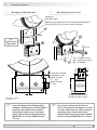
4 Montage
4.1 Montage des Geberrades
4.1.1 Schraubmontage
(MHGE 200 xx G)
4.1.2 Spannsatzmontage
(MHGE 200 xx Z, MHGE 200 xx Y)
4 Mounting
4.1 Mounting the encoder wheel
4.1.1 Screw mounting
(MHGE 200 xx G)
4.1.2 Clamping set mounting
(MHGE 200 xx Z, MHGE 200 xx Y)
Antriebswelle einfetten. Keine
magnetischen Werkzeuge benutzen.
Lubricate drive shaft.
Do not use magnetised tools.
Antriebswelle einfetten. Keine
magnetischen Werkzeuge benutzen.
Lubricate drive shaft.
Do not use magnetised tools.
øA
H7
, øC
h6
= 50...180 mm
øA
H7
, øC
h6
= 70...150 mm
øA
H7
øA
H7
øC
h6
øC
h6
4 mm
4 mm

MB201T1 - 11068569
Baumer_MHGE200-T1_II_DE-EN (19A3)
10
Montage / Mounting 4
T = +40...+120 °C
= T - (≥20 °C)
1.2 1.1
1
* *
*
Zul. Anzugsmoment:
Max. tightening torque:
M
t
= 3...4 Nm
3.4
3.5
*
*
3.2 3.1
* *
3
*
* Siehe Seite 6
See page 6
4.1 Montage des Geberrades
4.1.3 Heißschrumpfmontage
(MHGE 200 xx G)
Das Geberrad auf +40...+120 °C
erwärmen.
4.1.4 Klemmringmontage
(MHGE 200 xx K)
4.1 Mounting the encoder wheel
4.1.3 Shrink t mounting
(MHGE 200 xx G)
Warm up the encoder wheel to
+40...+120 °C.
4.1.4 Clamping ring mounting
(MHGE 200 xx K)
Antriebswelle einfetten. Keine
Induktionsöfen verwenden. Keine
magnetischen Werkzeuge benutzen.
Lubricate drive shaft.
Do not use induction ovens.
Do not use magnetised tools.
Antriebswelle einfetten. Keine
magnetischen Werkzeuge benutzen.
Lubricate drive shaft.
Do not use magnetised tools.
øA
H7
, øC
h6
= 70...160 mm
øA
H7
, øC
r6
= 50...180 mm
øA
H7
øA
H7
øC
r6
øC
h6
4 mm

11
Baumer_MHGE200-T1_II_DE-EN (19A3)
MB201T1 - 11068569
4 Montage / Mounting
4.2 Montage des Abtastkopfes 4.2 Mounting the sensor head
Unbedingt den zulässigen Luftspalt
zwischen Geberrad und Abtastkopf
einhalten. Bei Montage auf Bündigkeit
zwischen dem Geberrad und dem
Abtastkopf achten (max. zulässiger
Axialversatz während des Betriebes:
MHGE 200 x2: ±2 mm; MHGE 200 x5:
±3 mm).
Observe the permitted air gap between
the encoder wheel and the sensor
head. Check the ush alignment of the
encoder wheel and the sensor head on
mounting (max. permissible axial
displacement during operation: MHGE
200 x2: ±2 mm; MHGE 200 x5: ±3 mm).
Zulässiger Luftspalt:
Permitted air gap:
MHGE 200 x2:
0.3
±0.2
mm
MHGE 200 x5:
1
+1.2
mm
-0.9
0
MHGE 200 x2: ±2 mm
MHGE 200 x5: ±3 mm
Zul. Anzugsmoment:
Max. tightening torque:
M
t
= 8...10 Nm
Geberrad
Encoder wheel
Befestigungsmöglichkeit für den Abtastkopf (Beispiel).
Fixing element for the sensor head (example).
0
0
* Siehe Seite 7 oder 8
See page 7 or 8
*
4.8
4
4.1
*
*
*
4.8
4.9
*
Typenschild
Type label
6 mm

MB201T1 - 11068569
Baumer_MHGE200-T1_II_DE-EN (19A3)
12
L1
L1
L2
L3 + 39.5
L2
L3
C
Abmessungen / Dimensions 5
Nullimpuls-
markierung
Zero pulse
marker
Drehrichtung positiv
Positive rotating direction
Nicht vor-
handen
wenn
øA=180
Not present
iføA=180
3x Abdrückgewinde M5
3x Jack-screw thread M5
6x ø5.5
A
Ansicht A
View A
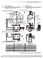
5 Abmessungen
5.1 Schraubmontage oder Heißschrumpf-
montage (MHGE 200 xx G)
5 Dimensions
5.1 Screw mounting or shrink t mounting
(MHGE 200 xx G)
Alle Abmessungen in Millimeter (wenn nicht anders angegeben)
All dimensions in millimeters (unless otherwise stated)
Polteilung/Pole pitch 2 mm:
MHGE 200 x2
Polteilung/Pole pitch 5 mm:
MHGE 200 x5
øA
H7
50...180 50...180
øB øA +15 (für/for øA=180+10) øA +15 (für/for øA=180+10)
øC 203.1 201.7
L1 (Luftspalt/Air gap) 0.3
±0.2
1
+1.2
L2 138.4 (bei/at L1 = 0.3) 138.5 (bei/at L1 = 1)
L3 166.9 (bei/at L1 = 0.3) 167 (bei/at L1 = 1)
-0.9
Abtastkopf mit Flanschdose
Sensorheadwithangeconnector
Abtastkopf mit Klemmenkasten
Sensor head with terminal box

13
Baumer_MHGE200-T1_II_DE-EN (19A3)
MB201T1 - 11068569
5 Abmessungen / Dimensions
L1
L1
L2
L3 + 39.5
L2
L3
B
H7
Nullimpuls-
markierung
Zero pulse
marker
Drehrichtung positiv
Positive rotating direction
A
Ansicht A
View A
5.2 Spannsatzmontage
(MHGE 200 xx Z, MHGE 200 xx Y)
5.2 Clamping set mounting
(MHGE 200 xx Z, MHGE 200 xx Y)
Polteilung/Pole pitch 2 mm:
MHGE 200 x2
Polteilung/Pole pitch 5 mm:
MHGE 200 x5
øA
H7
70...150 70...150
øB 203.1 201.7
L1 (Luftspalt/Air gap) 0.3
±0.2
1
+1.2
L2 138.4 (bei/at L1 = 0.3) 138.5 (bei/at L1 = 1)
L3 166.9 (bei/at L1 = 0.3) 167 (bei/at L1 = 1)
-0.9
Abtastkopf mit Flanschdose
Sensorheadwithangeconnector
Abtastkopf mit Klemmenkasten
Sensor head with terminal box
Alle Abmessungen in Millimeter (wenn nicht anders angegeben)
All dimensions in millimeters (unless otherwise stated)

MB201T1 - 11068569
Baumer_MHGE200-T1_II_DE-EN (19A3)
14
L1L1
L2
L3 + 39.5
L2
L3
B
Abmessungen / Dimensions 5
Polteilung/Pole pitch 2 mm:
MHGE 200 x2
Polteilung/Pole pitch 5 mm:
MHGE 200 x5
øA
H7
70...150 70...150
øB 203.1 201.7
L1 (Luftspalt/Air gap) 0.3
±0.2
1
+1.2
L2 138.4 (bei/at L1 = 0.3) 138.5 (bei/at L1 = 1)
L3 166.9 (bei/at L1 = 0.3) 167 (bei/at L1 = 1)
-0.9
5.3 Klemmringmontage
(MHGE 200 xx K)
5.3 Clamping ring mounting
(MHGE 200 xx K)
Abtastkopf mit Flanschdose
Sensorheadwithangeconnector
Abtastkopf mit Klemmenkasten
Sensor head with terminal box
Nullimpuls-
markierung
Zero pulse
marker
Drehrichtung positiv
Positive rotating direction
A
Ansicht A
View A
46 (øA <80 = 42)
Alle Abmessungen in Millimeter (wenn nicht anders angegeben)
All dimensions in millimeters (unless otherwise stated)

15
Baumer_MHGE200-T1_II_DE-EN (19A3)
MB201T1 - 11068569
6 Elektrischer Anschluss / Electrical connection
6 Elektrischer Anschluss
6.1 Beschreibung der Anschlüsse
6 Electrical connection
6.1 Terminal signicance
+UB; +
Betriebsspannung
Voltage supply
; ; GND; 0V
Masseanschluss
Ground
;
Erdungsanschluss (Gehäuse)
Earth ground (housing)
A+; K1
Ausgangssignal Kanal 1
Output signal channel 1
A−; K1
Ausgangssignal Kanal 1 invertiert
Output signal channel 1 inverted
B+; K2
Ausgangssignal Kanal 2 (90° versetzt zu Kanal 1)
Output signal channel 2 (offset by 90° to channel 1)
B−; K2
Ausgangssignal Kanal 2 invertiert
Output signal channel 2 inverted
R+; K0
Nullimpuls (Referenzsignal)
Zero pulse (reference signal)
R−; K0
Nullimpuls invertiert
Zero pulse inverted
xxx
Nicht benutzen
Do not use

MB201T1 - 11068569
Baumer_MHGE200-T1_II_DE-EN (19A3)
16
Elektrischer Anschluss / Electrical connection 6
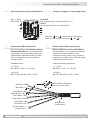
6.2 Ausgangssignale
6.2.1 Mit Rechtecksignalen:
(RN.... C, TN.... C, HN.... C und UN.... C)
6.2 Output signals
6.2.1 With square-wave signals:
(RN.... C, TN.... C, HN.... C and UN.... C)
Signalfolge bei
positiver Drehrichtung,
siehe Abschnitt 5.
Sequence for positive
rotating direction,
see section 5.
6.2.2 Mit SinCos-Signalen:
(SN.... C)
6.2.2 With SinCos signals:
(SN.... C)
360°el.
360°el.
90°el.
1 V
1 V
>0.4 V
[A+] − [A−] = Cos
= Sin[B+] − [B−]
[R+] − [R−]
0.5 V
2.5 V
A+
A−
Signalfolge bei
positiver Drehrichtung,
siehe Abschnitt 5.
Sequence for positive
rotating direction,
see section 5.
A+
A−
B+
B−
R+
R−
90°

17
Baumer_MHGE200-T1_II_DE-EN (19A3)
MB201T1 - 11068569
6 Elektrischer Anschluss / Electrical connection
6.3 Abtastkopf mit Flanschdose
6.3.1 Kabelanschluss Rundsteckverbinder -
Schritt 1
6.3 Sensor head with ange connector
6.3.1 Cable connection mating connector -
Step 1
Ansicht X
View X
81
2
3
4 5
11
6
7
9
10 12
* Siehe Seite 7 oder 8
See page 7 or 8
Ansicht X
Löteinsatz,
Belegung siehe
Abschnitt 6.3.3.
View X
Insert with
solder contacts,
assignment see
section 6.3.3.
Kabelschirm
Cable shield
ø7...12 mm
EMV-Ring
EMC ring
4 mm
≤25 mm
Code
Zur Gewährleistung der angegebenen
Schutzart sind nur geeignete Kabel-
durchmesser zu verwenden.
To ensure the specied protection of
the device the correct cable diameter
must be used.
Das Kabel muss abgeschirmt sein (ein
gemeinsamer Schirm) und verdrillte
Leitungspaare haben. Der Schirm
muss beidseitig am Stecker aufgelegt
sein.
A twisted pair cable must be used, it
has to be shielded (one combined
shield). The shield have to be
dispoced double-sided at the connec-
tor.
5
4.3
*
*
27 mm
24 mm
Seite wird geladen ...
Seite wird geladen ...
Seite wird geladen ...
Seite wird geladen ...
Seite wird geladen ...
Seite wird geladen ...
Seite wird geladen ...
Seite wird geladen ...
Seite wird geladen ...
Seite wird geladen ...
Seite wird geladen ...
Seite wird geladen ...
-
 1
1
-
 2
2
-
 3
3
-
 4
4
-
 5
5
-
 6
6
-
 7
7
-
 8
8
-
 9
9
-
 10
10
-
 11
11
-
 12
12
-
 13
13
-
 14
14
-
 15
15
-
 16
16
-
 17
17
-
 18
18
-
 19
19
-
 20
20
-
 21
21
-
 22
22
-
 23
23
-
 24
24
-
 25
25
-
 26
26
-
 27
27
-
 28
28
-
 29
29
-
 30
30
-
 31
31
-
 32
32


Verwandte Artikel
-
Baumer MHGE 800 Assembly Instruction
-
-
-
-
-
-
-
-
-
