
MB203 - 11071052
Baumer_MHGE800_II_DE-EN (19A3)
Montage- und Betriebsanleitung
Mounting and operating instructions
MHGE 800 - HDmag
Lagerloser Drehgeber - inkremental
Magnetische Abtastung
Encoder without bearings - incremental
Magnetic sensing

Baumer_MHGE800_II_DE-EN (19A3)
MB203 - 11071052
Inhaltsverzeichnis
Inhaltsverzeichnis
1 Allgemeine Hinweise ................................................................................................................................................ 1
2 Sicherheitshinweise
.................................................................................................................................................3
3 Vorbereitung
..................................................................................................................................................................5
3.1 Lieferumfang
..................................................................................................................................................... 5
3.1.1 Geberrad
.........................................................................................................................................................5
3.1.2 Abtastkopf
....................................................................................................................................................... 6
3.2 Zur Montage erforderlich (nicht im Lieferumfang enthalten)
...................................................6
3.3 Zur Demontage erforderlich (nicht im Lieferumfang enthalten)
............................................. 7
3.4 Erforderliches Werkzeug (nicht im Lieferumfang enthalten)
...................................................7
4 Montage
.............................................................................................................................................................................8
4.1 Montage des Geberrades
.......................................................................................................................... 8
4.1.1 Schraubmontage (MHGE 800 B5 G)
................................................................................................8
4.2 Montage des Abtastkopfes
........................................................................................................................9
5 Abmessung
.................................................................................................................................................................. 10
5.1 Schraubmontage (MHGE 800 B5 G)
................................................................................................ 10
6 Elektrischer Anschluss
........................................................................................................................................11
6.1 Beschreibung der Anschlüsse
...............................................................................................................11
6.2 Ausgangssignale
......................................................................................................................................... 12
6.3 Abtastkopf mit Flanschdose
.................................................................................................................. 13
6.3.1 Kabelanschluss Rundsteckverbinder - Schritt 1
..................................................................... 13
6.3.2 Kabelanschluss Rundsteckverbinder - Schritt 2
..................................................................... 14
6.3.3 Stiftbelegung Flanschdose
................................................................................................................. 14
6.4 Abtastkopf mit Klemmenkasten
........................................................................................................... 15
6.4.1 Kabelanschluss Anschlussplatine
................................................................................................... 15
6.4.2 Anschlussbelegung Anschlussplatine
.......................................................................................... 16
6.5 Sensorkabel HEK 8 (Zubehör)
............................................................................................................. 16
7 Demontage
....................................................................................................................................................................17
7.1 Demontage des Abtastkopfes
...............................................................................................................17
7.2 Demontage des Geberrades
................................................................................................................. 18
7.2.1 Schraubmontage (MHGE 800 B5 G)
............................................................................................. 18
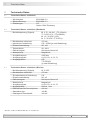
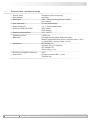
8 Technische Daten
.................................................................................................................................................... 19
8.1 Technische Daten - elektrisch
.............................................................................................................. 19
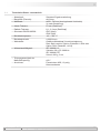
8.2 Technische Daten - elektrisch (Rechteck)
..................................................................................... 19
8.3 Technische Daten - elektrisch (SinCos)
.......................................................................................... 19
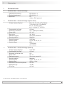
8.4 Technische Daten - mechanisch
......................................................................................................... 20
9 Zubehör
.......................................................................................................................................................................... 23

MB203 - 11071052
Baumer_MHGE800_II_DE-EN (19A3)
Table of contents
Table of contents
1 General notes ................................................................................................................................................................2
2 Security indications
.................................................................................................................................................. 4
3 Preparation
.....................................................................................................................................................................5
3.1 Scope of delivery
............................................................................................................................................ 5
3.1.1 Encoder wheel
.............................................................................................................................................. 5
3.1.2 Sensor head
..................................................................................................................................................6
3.2 Required for mounting (not included in scope of delivery)
....................................................... 6
3.3 Required for dismounting (not included in scope of delivery)
.................................................7
3.4 Required tools (not included in scope of delivery)
........................................................................ 7
4 Mounting
........................................................................................................................................................................... 8
4.1 Mounting the encoder wheel
....................................................................................................................8
4.1.1 Screw mounting (MHGE 800 B5 G)
..................................................................................................8
4.2 Mounting the sensor head
.........................................................................................................................9
5 Dimension
..................................................................................................................................................................... 10
5.1 Screw mounting (MHGE 800 B5 G)
.................................................................................................. 10
6 Electrical connection
.............................................................................................................................................11
6.1 Terminalsignicance
..................................................................................................................................11
6.2 Output signals
............................................................................................................................................... 12
6.3 Sensorheadwithangeconnector
................................................................................................... 13
6.3.1 Cable connection mating connector - Step 1
............................................................................ 13
6.3.2 Cable connection mating connector - Step 2
............................................................................ 14
6.3.3 Pinassignmentangeconnector
.................................................................................................... 14
6.4 Sensor head with terminal box
............................................................................................................. 15
6.4.1 Cable connection connecting board
.............................................................................................. 15
6.4.2 Terminal assignment connecting board
....................................................................................... 16
6.5 Sensor cable HEK 8 (accessory)
........................................................................................................ 16
7 Dismounting
................................................................................................................................................................ 17
7.1 Dismounting the sensor head
............................................................................................................... 17
7.2 Dismounting the encoder wheel
.......................................................................................................... 18
7.2.1 Screw mounting (MHGE 800 B5 G)
............................................................................................... 18
8 Technical data
............................................................................................................................................................ 21
8.1 Technical data - electrical ratings
....................................................................................................... 21
8.2 Technical data - electrical ratings (square-wave)
....................................................................... 21
8.3 Technical data - electrical ratings (SinCos)
................................................................................... 21
8.4 Technical data - mechanical design
.................................................................................................. 22
9 Accessories
................................................................................................................................................................. 23

1
Baumer_MHGE800_II_DE-EN (19A3)
MB203 - 11071052
1 Allgemeine Hinweise
1 Allgemeine Hinweise
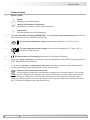
1.1 Zeichenerklärung:
Gefahr
Warnung bei möglichen Gefahren
Hinweis zur Beachtung
Hinweis zur Gewährleistung eines einwandfreien Betriebes des Gerätes
i
Information
Empfehlung für die Gerätehandhabung
1.2 Der lagerlose Drehgeber MHGE 800 ... ist ein Prä zi sionsmessgerät, das mit Sorgfalt nur von
technisch qualiziertem Per sonal gehandhabt werden darf.
1.3
Der Lagertemperaturbereich des Gerätes liegt zwischen -15 °C bis +70 °C.
1.4
Der Betriebstemperaturbereich des Gerätes liegt zwischen -40 °C bis +100 °C,
am Gehäuse gemessen.
1.5
EU-Konformitätserklärung gemäß den europäischen Richtlinien.
1.6 Wir gewähren 2 Jahre Gewährleistung im Rahmen der Bedingungen des Zentralverbandes der
Elektroindustrie (ZVEI).
1.7 Bei Rückfragen bzw. Nachlieferungen sind die auf dem Typenschild des Gerätes angege-
benen Daten, insbesondere Typ und Seriennummer, unbedingt anzugeben.
1.8
Entsorgung (Umweltschutz):
Gebrauchte Elektro- und Elektronikgeräte dürfen nicht im Hausmüll entsorgt werden.
Das Produkt enthält wertvolle Rohstoffe, die recycelt werden können. Wenn immer
möglich sollen Altgeräte lokal am entsprechenden Sammeldepot entsorgt werden. Im
Bedarfsfall gibt Baumer den Kunden die Möglichkeit, Baumer-Produkte fachgerecht zu entsor-
gen. Weitere Informationen siehe www.baumer.com.

MB203 - 11071052
Baumer_MHGE800_II_DE-EN (19A3)
2
General notes 1
1 General notes
1.1 Symbol guide:
Danger
Warnings of possible danger
General information for attention
Informations to ensure correct device operation
i
Information
Recommendation for device handling
1.2 The encoder without bearings MHGE 800 ... is a precision measurement device which must
be handled with care by skilled personnel only.
1.3
The storage temperature range of the device is between -15 °C and +70 °C.
1.4
The operating temperature range of the device is between -40 °C and +100 °C,
measured at the housing.
1.5
EU Declaration of Conformity meeting to the European Directives.
1.6 We grant a 2-year warranty in accordance with the regulations of the ZVEI (Central Association
of the German Electrical Industry).
1.7 In the event of queries or subsequent deliveries, the data on the device type label must be
quoted, especially the type designation and the serial number.
1.8
Disposal (environmental protection):
Do not dispose of electrical and electronic equipment in household waste. The product
contains valuable raw materials for recycling. Whenever possible, waste electrical and
electronic equipment should be disposed locally at the authorized collection point. If
necessary, Baumer gives customers the opportunity to dispose of Baumer products profession-
ally. For further information see www.baumer.com.

3
Baumer_MHGE800_II_DE-EN (19A3)
MB203 - 11071052
2 Sicherheitshinweise
2 Sicherheitshinweise
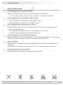
2.1 Verletzungsgefahr durch rotierende Wellen
Haare und Kleidungsstücke können von rotierenden Wellen erfasst werden.
• Vor allen Arbeiten alle Betriebsspannungen ausschalten und Maschinen stillsetzen.
2.2 Zerstörungsgefahr durch mechanische Überlastung
• Gerät nie senkrecht - das heißt auf das Magnetband - stellen.
• Das Magnetband darf mechanisch nicht belastet werden.
2.3 Zerstörungsgefahr durch mechanischen Schock
Starke Erschütterungen, z. B. Hammerschläge, können zur Zerstörung der Abtastung führen.
• Niemals Gewalt anwenden.
Bei sachgemäßer Montage lässt sich alles leichtgängig zusammenfügen.
• Für die Demontage geeignetes Abziehwerkzeug benutzen.
2.4 Zerstörungsgefahr durch klebende Flüssigkeiten
Klebende Flüssigkeiten können den Abtastkopf und das Geberrad beschädigen. Die Demontage
eines mit der Achse verklebten Gerätes kann zu dessen Zerstörung führen.
2.5 Explosionsgefahr
Das Gerät nicht in Bereichen mit explosionsgefährdeten bzw. leicht entzündlichen Materialien
verwenden.
Durch eventuelle Funkenbildung können diese leicht Feuer fangen und/oder explodieren.
2.6 Zerstörungsgefahr durch Fremdfelder
Fremdfelder können die Magnetisierung des Gerätes zerstören.

MB203 - 11071052
Baumer_MHGE800_II_DE-EN (19A3)
4
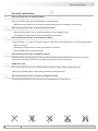
Security indications 2
2 Security indications
2.1 Risk of injury due to rotating shafts
Hair and clothes may become tangled in rotating shafts.
• Before all work switch off all voltage supplies and ensure machinery is stationary.
2.2 Risk of destruction due to mechanical overload
• Never set the device into a vertical position on the magnetic tape.
• The magnetic tape must not be mechanically overloaded.
2.3 Risk of destruction due to mechanical shock
Violent shocks, e. g. due to hammer impacts, can lead to the destruction of the sensing system.
• Never use force.
Mounting is simple when correct procedure is followed.
• Use suitable puller for dismounting.
2.4 Risk of destruction due to adhesive uids
Adhesiveuidscandamagethesensorheadandtheencoderwheel.Dismountingadevice,
secured to a shaft by adhesive may lead to the destruction of the device.
2.5 Explosion risk
Donotusethedeviceinareaswithexplosiveand/orhighlyinammablematerials.
Theymayexplodeand/orcatchrebypossiblesparkformation.
2.6 Risk of destruction due to external magnetic elds
Externalmagneticeldsmaydestructthemagnetizationofthedevice.

5
Baumer_MHGE800_II_DE-EN (19A3)
MB203 - 11071052
3 Vorbereitung
3.1 Lieferumfang
3.1.1 Geberrad
3 Preparation
3.1 Scope of delivery
3.1.1 Encoder wheel
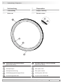
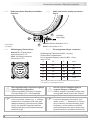
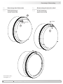
3 Vorbereitung / Preparation
1
Geberrad für Schraubmontage
(MHGE 800 B5 G)
1.1
Inkrementalspur
1.2
Nullimpulsspur
1.3
Nullimpulsmarkierung
1.4
6x Befestigungsbohrung ø8,5 mm
1.5
3x Abdrückgewinde M8
1
Encoder wheel for screw mounting
(MHGE 800 B5 G)
1.1
Incremental track
1.2
Zero pulse track
1.3
Zero pulse marker
1.4
6xxingboreø8.5mm
1.5
3x jack-screw thread M8
1
1.5
1.4
1.3
1.1
1.2

MB203 - 11071052
Baumer_MHGE800_II_DE-EN (19A3)
6
Vorbereitung / Preparation 3
3.1 Lieferumfang
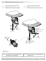
3.1.2 Abtastkopf
3.1 Scope of delivery
3.1.2 Sensor head
2
2
2.1 2.1 2.7
2.62.42.5
2.2
2.3
2.8
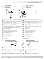
3.2 Zur Montage erforderlich
(nicht im Lieferumfang enthalten)
3.2 Required for mounting
(not included in scope of delivery)
3
Sensorkabel HEK 8, als Zubehör erhältlich,
siehe Abschnitt 6.5.
1.6
Befestigungsschraube ISO 4762, M8x35 mm
bei Geberrad für Schraubmontage, siehe
1
in Abschnitt 3.1.1.
2.9
Befestigungsschraube ISO 4762, M8x45 mm
3
Sensor cable HEK 8, available as accessory,
see section 6.5.
1.6
Fixing screw ISO 4762, M8x35 mm
for encoder wheel for screw mounting, see
1
in section 3.1.1.
2.9
Fixing screw ISO 4762, M8x45 mm
3
1.6 2.9
6x 2x
2
Abtastkopf mit Standard-Signalverarbei-
tung
2.1
Zyl. Senkung für M8, ISO 4762
2.2
1)
Flanschdose M23, 12-polig, Stiftkontakte,
linksdrehend, siehe Abschnitt 6.3.3.
2.3
1)
Rundsteckverbinder M23, 12-polig, Buchsen-
kontakte, rechtsdrehend, s. Abschnitt 6.3.1.
2.4
1)
Klemmenkasten
2.5
1)
Torx-/Schlitzschraube M4x32 mm
2.6
1)
Kabelverschraubung M20x1,5 mm
für Kabel ø5...13 mm
2.7
1)
Anschlussplatine,
siehe Abschnitt 6.4.2.
2.8
Abstandslehre 1 mm
1)
Je nach Version
2
Sensor head with standard signal process-
ing
2.1
Cyl. counterbore for M8, ISO 4762
2.2
1)
Flange connector M23, 12-pin, male, CCW,
see section 6.3.3.
2.3
1)
Mating connector, 12-pin, female, CW, see
section 6.3.1.
2.4
1)
Terminal box
2.5
1)
Torx/slotted screw M4x32 mm
2.6
1)
Cable gland M20x1.5 mm
forcableø5...13mm
2.7
1)
Connecting board,
see section 6.4.2.
2.8
Clearance gage 1 mm
1)
Depending on version
1)
1)
1)
1)1)
1)

7
Baumer_MHGE800_II_DE-EN (19A3)
MB203 - 11071052
3 Vorbereitung / Preparation
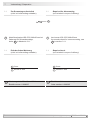
3.3 Zur Demontage erforderlich
(nicht im Lieferumfang enthalten)
3.3 Required for dismounting
(not included in scope of delivery)
1.7
Abdrückschraube ISO 4762, M8x20 mm bei
Geberrad für Schraubmontage,
siehe
1
in Abschnitt 3.1.1.
1.7
Jack screw ISO 4762, M8x20 mm
for encoder wheel for screw mounting, see
1
in section 3.1.1.
3.4 Erforderliches Werkzeug
(nicht im Lieferumfang enthalten)
3.4 Required tools
(not included in scope of delivery)
1.7
3x
4
Werkzeugset als Zubehör erhältlich:
Bestellnummer 11068265
4
Tool kit available as accessory:
Order number 11068265
6 mm
24 und 27 mm
6 mm
24 and 27 mm

MB203 - 11071052
Baumer_MHGE800_II_DE-EN (19A3)
8
Montage / Mounting 4
1.6
*
Zul. Anzugsmoment:
Max. tightening torque:
M
t
= 8...10 Nm
1
*
* Siehe Seite 5 oder 6
See page 5 or 6
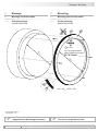
4 Montage
4.1 Montage des Geberrades
4.1.1 Schraubmontage
(MHGE 800 B5 G)
4 Mounting
4.1 Mounting the encoder wheel
4.1.1 Screw mounting
(MHGE 800 B5 G)
Antriebswelle einfetten. Keine
magnetischen Werkzeuge benutzen.
Lubricate drive shaft.
Do not use magnetised tools.
1.2
1.1
*
*
6 mm
øA
H7
, øC
h6
= 650...740
øA
H7
øC
h6

9
Baumer_MHGE800_II_DE-EN (19A3)
MB203 - 11071052
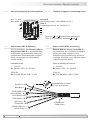
4 Montage / Mounting
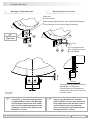
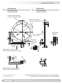
4.2 Montage des Abtastkopfes 4.2 Mounting the sensor head
Unbedingt auf einen Luftspalt von
nominell 1
+1.2
mm zwischen Geberrad
und Abtastkopf achten. Bei Montage
auf Bündigkeit zwischen dem Geber-
rad und dem Abtastkopf achten (max.
zulässiger Axialversatz während des
Betriebes: ±3 mm).
Make sure there is an 1
+1.2
mm nomi-
nally air gap between the encoder
wheel and the sensor head. Check the
ush alignment of the encoder wheel
and the sensor head on mounting
(max. permissible axial displacement
during operation: ±3 mm).
-0.9
-0.9
-0.9
1
+1.2
Luftspalt
Air gap
±3 mm
Zul. Anzugsmoment:
Max. tightening torque:
M
t
= 8...10 Nm
Zulässiger Axialversatz zwischen
Abtastkopf und Geberrad
Permissible axial displacement
between the sensor head and the
encoder wheel
0
0
* Siehe Seite 6
See page 6
*
2.1
*
2.8
2.9
*
Geberrad
Encoder wheel
Befestigungsmöglichkeit für den Abtastkopf (Beispiel).
Fixing element for the sensor head (example).
2.8
2
*
*
Typenschild
Type label
6 mm
0

MB203 - 11071052
Baumer_MHGE800_II_DE-EN (19A3)
10
H7
Abmessung / Dimension 5
Nullimpuls-
markierung
Zero pulse
marker
Drehrichtung positiv
Positive rotating direction
3x Abdrückgewinde M8
3x Jack-screw thread M8
Luftspalt
Air gap
2)
Bei einem Luftspalt von 1 mm
2)
At an air gap of 1 mm
6x ø8.5
øA
H7
= 650...740
øB = øA +25
A
Ansicht A
View A
Alle Abmessungen in Millimeter (wenn nicht anders angegeben)
All dimensions in millimeters (unless otherwise stated)
5 Abmessung
5.1 Schraubmontage
(MHGE 800 B5 G)
5 Dimension
5.1 Screw mounting
(MHGE 800 B5 G)
Luftspalt
Air gap
Abtastkopf mit Flanschdose
Sensorheadwithangeconnector
Abtastkopf mit Klemmenkasten
Sensor head with terminal box
2)
2)
2)
2)

11
Baumer_MHGE800_II_DE-EN (19A3)
MB203 - 11071052
6 Elektrischer Anschluss / Electrical connection
6 Elektrischer Anschluss
6.1 Beschreibung der Anschlüsse
6 Electrical connection
6.1 Terminal signicance
+UB; +
Betriebsspannung
Voltage supply
; ; GND; 0V
Masseanschluss
Ground
;
Erdungsanschluss (Gehäuse)
Earth ground (housing)
A+; K1
Ausgangssignal Kanal 1
Output signal channel 1
A-; K1
Ausgangssignal Kanal 1 invertiert
Output signal channel 1 inverted
B+; K2
Ausgangssignal Kanal 2 (90° versetzt zu Kanal 1)
Output signal channel 2 (offset by 90° to channel 1)
B-; K2
Ausgangssignal Kanal 2 (90° versetzt zu Kanal 1) invertiert
Output signal channel 2 (offset by 90° to channel 1) inverted
R+; K0
Nullimpuls (Referenzsignal)
Zero pulse (reference signal)
R-; K0
Nullimpuls (Referenzsignal) invertiert
Zero pulse (reference signal) inverted
xxx
Nicht benutzen
Do not use

MB203 - 11071052
Baumer_MHGE800_II_DE-EN (19A3)
12
Elektrischer Anschluss / Electrical connection 6
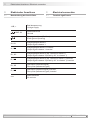
6.2 Ausgangssignale
6.2.1 Mit Rechtecksignalen:
(RN.... C, TN.... C, HN.... C und UN.... C)
6.2 Output signals
6.2.1 With square-wave signals:
(RN.... C, TN.... C, HN.... C and UN.... C)
Signalfolge bei
positiver Drehrichtung,
siehe Abschnitt 5.
Sequence for positive
rotating direction,
see section 5.
6.2.2 Mit SinCos-Signalen:
(SN.... C)
6.2.2 With SinCos signals:
(SN.... C)
360°el.
360°el.
90°el.
1 V
1 V
>0.4 V
[A+] – [A-] = Cos
= Sin[B+] – [B-]
[R+] – [R-]
0.5 V
2.5 V
A+
A-
Signalfolge bei
positiver Drehrichtung,
siehe Abschnitt 5.
Sequence for positive
rotating direction,
see section 5.
A+
A-
B+
B-
R+
R-
90°

13
Baumer_MHGE800_II_DE-EN (19A3)
MB203 - 11071052
6 Elektrischer Anschluss / Electrical connection
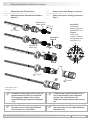
6.3 Abtastkopf mit Flanschdose
6.3.1 Kabelanschluss Rundsteckverbinder -
Schritt 1
6.3 Sensor head with ange connector
6.3.1 Cable connection mating connector -
Step 1
Ansicht X
View X
81
2
3
4 5
11
6
7
9
10 12
* Siehe Seite 7 oder 8
See page 7 or 8
Ansicht X
Löteinsatz,
Belegung siehe
Abschnitt 6.3.3.
View X
Insert with
solder contacts,
assignment see
section 6.3.3.
Kabelschirm
Cable shield
ø7...12 mm
EMV-Ring
EMC ring
4 mm
≤25 mm
Code
Zur Gewährleistung der angegebenen
Schutzart sind nur geeignete Kabel-
durchmesser zu verwenden.
To ensure the specied protection of
the device the correct cable diameter
must be used.
Das Kabel muss abgeschirmt sein (ein
gemeinsamer Schirm) und verdrillte
Leitungspaare haben. Der Schirm
muss beidseitig am Stecker aufgelegt
sein.
A twisted pair cable must be used, it
has to be shielded (one combined
shield). The shield have to be
dispoced double-sided at the connec-
tor.
27 mm
24 mm
3
2.3
*
*

MB203 - 11071052
Baumer_MHGE800_II_DE-EN (19A3)
14
Elektrischer Anschluss / Electrical connection 6
6.3.2 Kabelanschluss Rundsteckverbinder -
Schritt 2
6.3.2 Cable connection mating connector -
Step 2
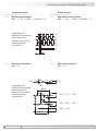
6.3.3 Stiftbelegung Flanschdose 6.3.3 Pin assignment ange connector
1 8
9
10 12
2 7
11
3 6
4 5
Ansicht Y in Flanschdose,
siehe Abschnitt 6.3.2.
View Yinangeconnector,
see section 6.3.2.
Stiftbelegung Flanschdose M23, 12-polig,
Stiftkontakte, linksdrehend.
PinassignmentangeconnectorM23,12-pin,
male, CCW.
1 B- 7 xxx
3)
2 xxx
3)
8 B+
3 R+ 9 xxx
3)
4 R- 10
5 A+ 11 xxx
3)
6 A- 12 +UB
3)
Benutzung des Stifts kann zur Beschädigung des Gerätes führen
3)
Use of the pin can damage the device
Betriebsspannung nicht auf Ausgänge
legen! Zerstörungsgefahr!
Spannungsabfälle in langen Leitungen
berücksichtigen (Ein- und Ausgänge).
Das Gerät muss immer aus der Folgelek-
tronik (Umrichter, Steuerung, ...) versorgt
werden bzw. mindestens eine sehr gute
Masseverbindung (Hochfrequenz) haben,
die für ein gleiches Potential zwischen
Geräteversorgung und Geräteauswertee-
lektronik sorgt.
The device must receive the power supply
from the subsequent electronics (con-
verter, control, ...). Alternative it is neces-
sary to have an excellent bonding (high-
frequency), which enables consistent
potential between the device power sup-
ply and the device evaluation electronics.
Do not connect voltage supply to
outputs! Danger of damage!
Please, beware of possible voltage drop
in long cable leads (inputs and outputs).
Ansicht Y siehe Abschnitt 6.3.3.
View Y see section 6.3.3.
2
2.2
2.3
*
*
*
Handfest
Hand-tight
* Siehe Seite 6
See page 6

15
Baumer_MHGE800_II_DE-EN (19A3)
MB203 - 11071052
Ansicht Z
siehe Abschnitt 6.4.2.
View Z
see section 6.4.2.
6.4 Abtastkopf mit Klemmenkasten
6.4.1 Kabelanschluss Anschlussplatine
6.4 Sensor head with terminal box
6.4.1 Cable connection connecting board
2
2.6
2.42.5
2.7
3
*
Kabelschirm
Cable shield
* Siehe Seite 7 oder 8
See page 7 or 8
Zur Gewährleistung der angegebenen
Schutzart sind nur geeignete Kabel-
durchmesser zu verwenden.
To ensure the specied protection of
the device the correct cable diameter
must be used.
ø5...13 mm
TX 20
22 mm
Zul. Anzugsmoment:
Max. tightening torque:
M
t
= 2...3 Nm
6 Elektrischer Anschluss / Electrical connection

MB203 - 11071052
Baumer_MHGE800_II_DE-EN (19A3)
16
Elektrischer Anschluss / Electrical connection 6
6.4.2 Anschlussbelegung Anschlussplatine 6.4.2 Terminal assignment connecting board
Ansicht Z
Anschlussklemmen, siehe Abschnitt 6.4.1.
View Z
Connecting terminal, see section 6.4.1.
Max. 1,5 mm
2
Max. AWG 16
Zwischen und besteht keine Verbindung.
There is no connection between and .
K0
K2
K1
K0
+UB
K1
K2
6.5 Sensorkabel HEK 8 (Zubehör)
Es wird empfohlen, das Baumer Hübner
Sensorkabel HEK 8 zu verwenden oder
ersatzweise ein geschirmtes, paarig ver-
seiltes Kabel. Das Kabel sollte in einem
Stück und getrennt von Stromkabeln
verlegt werden.
Kabelabschluss:
1 ... 3 kΩ für:
HN, UN bei +UB = 10...30 VDC
120 Ω für:
RN, TN, SN, UN bei +UB = 5 VDC
6.5 Sensor cable HEK 8 (accessory)
Baumer Hübner sensor cable HEK 8 is
recommended. As a substitute a shielded
twisted pair cable should be used.
Continuous wiring without any splices or
couplings should be used. Separate signal
cables from power cables.
Cable terminating resistance:
1...3kΩfor:
HN, UN at +UB = 10...30 VDC
120Ωfor:
RN, TN, SN, UN at +UB = 5 VDC
Aderendhülsen benutzen.
Use core-end ferrules.
Rot/Red = +UB
Weiß/White = A+
Braun/Brown = A-
Grün/Green = B+
Grau/Grey = R+
Rosa/Pink = R-
Gelb/ Yellow = B-
Kabelschirm
Cable shield
Blau/Blue =
Schwarz/Black = ---
Violett/Violet = ---

17
Baumer_MHGE800_II_DE-EN (19A3)
MB203 - 11071052
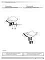
7 Demontage
7.1 Demontage des Abtastkopfes
7 Dismounting
7.1 Dismounting the sensor head
2.1
*
2.5
*
6 mm
7 Demontage / Dismounting
Disconnect all electric connections
and ensure machinery is stationary
before dismounting the device.
* Siehe Seite 6
See page 6
Vor Demontage des Gerätes alle
elektrischen Verbindungen trennen
und Maschinen stillsetzen.
Seite wird geladen ...
Seite wird geladen ...
Seite wird geladen ...
Seite wird geladen ...
Seite wird geladen ...
Seite wird geladen ...
Seite wird geladen ...
Seite wird geladen ...
-
 1
1
-
 2
2
-
 3
3
-
 4
4
-
 5
5
-
 6
6
-
 7
7
-
 8
8
-
 9
9
-
 10
10
-
 11
11
-
 12
12
-
 13
13
-
 14
14
-
 15
15
-
 16
16
-
 17
17
-
 18
18
-
 19
19
-
 20
20
-
 21
21
-
 22
22
-
 23
23
-
 24
24
-
 25
25
-
 26
26
-
 27
27
-
 28
28


Verwandte Artikel
-
Baumer MHGE 100 Assembly Instruction
-
-
-
-
-
-
-
-
-