Olimpia Splendid control - B0151-B0152 Benutzerhandbuch
- Typ
- Benutzerhandbuch
Seite laden ...

GB
F
D
2
I
4
4
6
6
8
8
10
10
12
14
14
14
14
18
18
18
20
22
22
24
24
24
26
28
28
30
30
30
32
32
32
34
34
1 ALLGEMEINES
1.1 ALLGEMEINE
INFORMATIONEN
1.2 SYMBOLGEBUNG
1.3 TABELLE DER
ELEKTRISCHEN
EIGENSCHAFTEN
2 MONTAGEANLEITUNG
2.1 ÖFFNUNG DER SEITEN
2.2 INSTALLATION DER
VENTILATORSTEUERUNG
FÜR FERNREGELUNG
B0542
2.2.1 Installation B0542
2.2.2 Anschlüsse B0542
2.3 INSTALLATION
STEUERUNG AN DER
WAND MIT THERMOSTAT,
WAHLSCHALTER
SOMMER/WINTER UND
CHWINDIGKEITSWÄHLER
B0151
2.3.1 Positionierung
2.3.2 Montage
2.3.3 Anschlüsse B0151
2.4 EINFASSSTEUERUNG
MIT THERMOSTAT
UND WAHLSCHALTER
SOMMER/WINTER
SOWIE WAHLSCHALTER
GESCHWINDIGKEIT
B0152
2.4.1 Positionierung
2.4.2 Montage
2.4.3 Anschlüsse B0152
3 BEDIENUNG UND
WARTUNG
3.1 STEUERUNG AN DER
WAND MIT THERMOSTAT
UND WAHLSCHALTER
SOMMER/WINTER
SOWIE WAHLSCHALTER
GESCHWINDIGKEIT
(B0151)
3.1.1 Haupteinschaltung
3.1.2 Aktivierung
3.1.3 Regelung der
Belüftungsgeschwindigkeit
3.2 EINFASSSTEUERUNG
MIT THERMOSTAT
UND WAHLSCHALTER
SOMMER/WINTER
SOWIE WAHLSCHALTER
GESCHWINDIGKEIT
(B0152)
3.2.1 Einstellung Sommer/Winter
3.2.2 Temperatureinstellung
3.2.3 ON/OFF Einstellung
3.2.4 Einstellung der
Ventilatorgeschwindigkeit
3.2.5 Automatikbetrieb des
Ventilators
3.2.6 Reset
3.2.7 Tastatursperre
3.2.8 Funktion Erfassung der
Wassertemperatur im
Innern der Ventil-Konvektor-
Batterien
3.2.9 Deaktivierung
3.2.10 Ausschalten für lange
1 GENERALITA’
1.1 INFORMAZIONI
GENERALI
1.2 SIMBOLOGIA
1.3 TABELLA
CARATTERISTICHE
ELETTRICHE
2 ISTRUZIONI
MONTAGGIO
2.1 APERTURA FIANCHI
2.2 INSTALLAZIONE
CONTROLLO
VENTILATORE PER
REGOLAZIONE REMOTA
B0542
2.2.1 Installazione B0542
2.2.2 Collegamenti B0542
2.3 INSTALLAZIONE
COMANDO A PARETE
CON TERMOSTATO,
SELETTORE ESTATE/
INVERNO E SELETTORE
VELOCITA’ B0151
2.3.1 Posizionamento
2.3.2 Montaggio
2.3.3 Collegamenti B0151
2.4 INSTALLAZIONE
COMANDO AD INCASSO
CON TERMOSTATO,
SELETTORE ESTATE/
INVERNO E SELETTORE
VELOCITA’ B0152
2.4.1 Posizionamento
2.4.2 Montaggio
2.4.3 Collegamenti B0152
3 USO E
MANUTENZIONE
3.1 COMANDO A PARETE
CON TERMOSTATO E
SELETTORE ESTATE/
INVERNO E SELETTORE
VELOCITÀ (B0151)
3.1.1 Accensione generale
3.1.2 Attivazione
3.1.3 Regolazione velocità di
ventilazione
3.2 COMANDO AD INCASSO
CON TERMOSTATO,
SELETTORE ESTATE/
INVERNO E SELETTORE
VELOCITÀ (B0152)
3.2.1 Impostazione Estate/
Inverno
3.2.2 Impostazione della
temperatura
3.2.3 Impostazione on/off
3.2.4 Impostazione velocità
ventola
3.2.5 Funzionamento automatico
della ventola
3.2.6 Reset
3.2.7 Blocco tastiera
3.2.8 Funzioni di rilevamento
della temperatura dell’acqua
all’interno della batteria del
ventilconvettore
3.2.9 Disattivazione
3.2.10 Spegnimento per lunghi
1 GENERAL
1.1 INFORMATION GENERAL
1.2 SYMBOLS
1.3 ELECTRICAL
CHARACTERISTICS
TABLE
2 MOUNTING
INSTRUCTIONS
2.1 OPENING SIDES
2.2 INSTALLATION FAN
CONTROL FOR REMOTE
ADJUSTMENT B0542
2.2.1 B0542 Installation
2.2.2 B0542 Connections
2.3 B0151 INSTALLATION
OF WALL MOUNTED
CONTROL WITH
THERMOSTAT, SUMMER/
WINTER SELECTOR, AND
SPEED SELECTOR
2.3.1 Positioning
2.3.2 Mounting
2.3.3 B0151 connections
2.4 INSTALLATION OF
EMBEDDED CONTROL
WITH THERMOSTAT,
SUMMER/WINTER
SELECTOR AND SPEED
SELECTOR B0152
2.4.1 Positioning
2.4.2 Mounting
2.4.3 B0152 connections
3 USE AND
MAINTENANCE
3.1 WALL MOUNTED
CONTROL WITH
SUMMER/WINTER
SELECTOR,
THERMOSTAT AND
SPEED SELECTOR
(B0151)
3.1.1 Switching on the system
3.1.2 Activation
3.1.3 Ventilation speed
adjustment
3.2 EMBEDDED CONTROL
WITH THERMOSTAT,
SUMMER/WINTER
SELECTOR AND SPEED
SELECTOR (B0152)
3.2.1 Summer/winter setting
3.2.2 Temperature setting
3.2.3 On/off Setting
3.2.4 Fan speed setting
3.2.5 Automatic fan operation
3.2.6 Reset
3.2.7 Keypad block
3.2.8 Detection of the water
temperature inside the
cooler-convector battery
3.2.9 Deactivation
3.2.10 Shutdown for long periods
1 GENERALITES
1.1 INFORMATIONS
GENERALES
1.2 SYMBOLES
1.3 TABLEAU
CARACTÉRISTIQUES
ÉLECTRIQUES
2 INSTRUCTIONS DE
MONTAGE
2.1 OUVERTURE FLANCS
2.2 INSTALLATION
CONTROLE
VENTILATEUR POUR
REGLAGE A DISTANCE
B0542
2.2.1 Installation B0542
2.2.2 Branchements B0542
2.3 INSTALLATION
COMMANDE MURALE
AVEC THERMOSTAT,
SELECTEUR ETE/HIVER
ET SELECTEUR DE
VITESSE B0151
2.3.1 Mise en place
2.3.2 Montage
2.3.3 Branchements B0151
2.4 INSTALLATION
COMMANDE
ENCASTRABLE
AVEC THERMOSTAT,
SELECTEUR ETE/HIVER
ET SELECTEUR DE
VITESSE B0152
2.4.1 Mise en place
2.4.2 Montage
2.4.3 Branchements B0152
3 UTILISATION ET
ENTRETIEN
3.1 COMMANDE MURALE
AVEC THERMOSTAT ET
SELECTEUR ETE/HIVER
ET SELECTEUR DE
VITESSE (B0151)
3.1.1 Allumage général
3.1.2 Activation
3.1.3 Réglage vitesse de
ventilation
3.2 COMMANDE
ENCASTRABLE
AVEC THERMOSTAT,
SELECTEUR ETE/HIVER
ET SELECTEUR DE
VITESSE (B0152)
3.2.1 Réglage été/hiver
3.2.2 Réglage de la température
3.2.3 Réglage on/off
3.2.4 Réglage de la vitesse du
ventilateur
3.2.5 Fonctionnement
automatique du ventilateur
3.2.6 Reset
3.2.7 Blocage clavier
3.2.8 Fonctions de mesure de
la température de l'eau à
l'intérieur de la batterie du
ventilateur-convecteur
3.2.9 Désactivation
3.2.10 Extinction pendant de
longues périodes

E P NL
3
GR
5
5
7
7
9
9
11
11
13
15
15
15
15
19
19
19
21
23
23
25
25
25
27
29
29
31
31
31
33
33
33
35
35
1 NOÇÕES GERAIS
1.1 INFORMAÇÕES GERAIS
1.2 SIMBOLOGIA
1.3 TABELA DAS
CARACTERÍSTICAS
ELÉCTRICAS
2 INSTRUÇÕES PARA A
MONTAGEM
2.1 ABERTURA DAS
LATERAIS
2.2 INSTALAÇÃO DO
CONTROLO DO
VENTILADOR PARA
REGULAÇÃO À
DISTÂNCIA B0542
2.2.1 Instalação B0542
2.2.2 Ligações B0542
2.3 INSTALAÇÃO DO
COMANDO DE PAREDE
COM TERMÓSTATO,
SELECTOR DE VERÃO/
INVERNO E SELECTOR
DE VELOCIDADE B0151
2.3.1 Posicionamento
2.3.2 Montagem
2.3.3 Ligações do B0151
2.4 INSTALAÇÃO DO
COMANDO DE EMBUTIR
COM TERMÓSTATO,
SELECTOR DE VERÃO/
INVERNO E SELECTOR
DE VELOCIDADE B0152
2.4.1 Posicionamento
2.4.2 Montagem
2.4.3 Ligações B0152
3 USO E MANUTENÇÃO
3.1 COMANDO DE PAREDE
COM TERMÓSTATO E
SELECTOR DE VERÃO/
INVERNO E SELECTOR
DE VELOCIDADE (B0151)
3.1.1 Ligação geral
3.1.2 Activação
3.1.3 Regulação da velocidade
de ventilação
3.2 COMANDO EMBUTIDO
COM TERMÓSTATO,
SELECTOR DE VERÃO/
INVERNO E SELECTOR
DE VELOCIDADE (B0152)
3.2.1 Programação de Verão/
Inverno
3.2.2 Programação da
temperatura
3.2.3 Programação de ON/OFF
3.2.4 Programação da velocidade
da ventoinha
3.2.5 Funcionamento automático
da ventoinha
3.2.6 Reset
3.2.7 Bloqueio dos botões
3.2.8 Funções de detecção
da temperatura da água
no interior da bateria do
ventiloconvector
3.2.9 Desactivação
3.2.10 Desligação por períodos
prolongados
1 ÃÅÍÉÊÁ
1.1 ÃÅÍÉÊÅÓ ÐËÇÑÏÖÏÑÉÅÓ
1.2 ÓÕÌÂÏËÁ
1.3 ÐÉÍÁÊÁÓ ÇËÅÊÔÑÉÊÙÍ
×ÁÑÁÊÔÇÑÉÓÔÉÊÙÍ
2 ÏÄÇÃÉÅÓ
ÔÏÐÏÈÅÔÇÓÇÓ
2.1 ÁÍÏÉÃÌÁ ÐËÁÚÍÙÍ
2.2 ÔÏÐÏÈÅÔÇÓÇ ÅËÅÃXÏÕ
ÁÍÅÌÉÓÔÇÑÁ ÃÉÁ
ÑÕÈÌÉÓÇ ÁÐÏ ÌÁÊÑÉÁ
Â0138
2.2.1 ÅãêáôÜóôáóç Â0138
2.2.2 ÓõíäÝóåéò Â0138
2.3 ÔÏÐÏÈÅÔÇÓÇ
ÅÐÉÔÏÉ×ÉÁÓ ÅÍÔÏËÇÓ
ÌÅ ÈÅÑÌÏÓÔÁÔÇ,
ÅÐÉËÏÃÅÁ
ÊÁËÏÊÁÉÑÉ/×ÅÉÌÙÍÁ ÊÁÉ
ÅÐÉËÏÃÅÁ ÔÁ×ÕÔÇÔÁÓ
Â0151
2.3.1 ÈÝóç
2.3.2 ÔïðïèÝôçóç
2.3.3 ÓõíäÝóåéò Â0151
2.4 ÔÏÐÏÈÅÔÇÓÇ
×ÙÍÅÕÔÇÓ ÅÍÔÏËÇÓ
ÌÅ ÈÅÑÌÏÓÔÁÔÇ,
ÅÐÉËÏÃÅÁ
ÊÁËÏÊÁÉÑÉ/×ÅÉÌÙÍÁ ÊÁÉ
ÅÐÉËÏÃÅÁ ÔÁ×ÕÔÇÔÁÓ
Â0152
2.4.1 ÈÝóç
2.4.2 ÔïðïèÝôçóç
2.4.3 ÓõíäÝóåéò Â0152
3 ×ÑÇÓÇ ÊÁÉ
ÓÕÍÔÇÑÇÓÇ
3.1 ÅÐÉÔÏÉ×ÉÁ ÅÍÔÏËÇ
ÌÅ ÈÅÑÌÏÓÔÁÔÇ
ÊÁÉ ÅÐÉËÏÃÅÁ
ÊÁËÏÊÁÉÑÉ/×ÅÉÌÙÍÁ ÊÁÉ
ÅÐÉËÏÃÅÁ ÔÁ×ÕÔÇÔÁÓ
(Â0151)
3.1.1 Ãåíéêü Üíáììá
3.1.2 Åíåñãïðïßçóç
3.1.3 Ñýèìéóç ôá÷ýôçôáò
áíåìéóôÞñá
3.2 ×ÙÍÅÕÔÇ ÅÍÔÏËÇ
ÌÅ ÈÅÑÌÏÓÔÁÔÇ,
ÅÐÉËÏÃÅÁÓ
ÊÁËÏÊÁÉÑÉ/×ÅÉÌÙÍÁ ÊÁÉ
ÅÐÉËÏÃÅÁÓ ÔÁ×ÕÔÇÔÁÓ
(Â0152)
3.2.1 Êáèïñéóìüò
Êáëïêáßñé/×åéìþíáò
3.2.2 Êáèïñéóìüò ôçò
èåñìïêñáóßáò
3.2.3 Êáèïñéóìüò on/off
3.2.4 Êáèïñéóìüò ôá÷ýôçôáò
öôåñùôÞò
3.2.5 Áõôüìáôç ëåéôïõñãßá ôçò
öôåñùôÞò
3.2.6 Reset
3.2.7 ÅìðëïêÞ ÷åéñéóôçñßïõ
3.2.8 Ëåéôïõñãßåò åíôïðéóìïý
ôçò èåñìïêñáóßáò ôïõ
íåñïý óôï åóùôåñéêü ôçò
ìðáôáñßáò ôïõ áíåìéóôÞñá
áãùãþí èåñìüôçôáò
3.2.9 Áðåíåñãïðïßçóç
3.2.10 ÓâÞóéìï ãéá ìåãÜëá
÷ñïíéêÜ äéáóôÞìáôá
1 ALGEMEEN
1.1 ALGEMENE INFORMATIE
1.2 SYMBOLEN
1.3 TABEL ELEKTRISCHE
KENMERKEN
2 INSTRUCTIES VOOR
DE MONTAGE
2.1 OPENING ZIJKANTEN
2.2 INSTALLATIE CONTROLE
VENTILATOR VOOR
AFSTANDSBEDIENING
B0542
2.2.1 Installatie B0542
2.2.2 Aansluitingen B0542
2.3 INSTALLATIE
MUURBEDIENING
MET THERMOSTAAT,
KEUZESCHAKELAAR
ZOMER/WINTER EN
KEUZESCHAKELAAR
SNELHEID B0151
2.3.1 Positionering
2.3.2 Montage
2.3.3 Aansluitingen B0151
2.4 INSTALLATIE
INGEBOUWDE
BEDIENING MET
THERMOSTAAT,
KEUZESCHAKELAAR
ZOMER/WINTER EN
KEUZESCHAKELAAR
SNELHEID B0152
2.4.1 Positionering
2.4.2 Montage
2.4.3 Aansluitingen B0152
3 GEBRUIK EN
ONDERHOUD
3.1 MUURBEDIENING
MET THERMOSTAAT,
KEUZESCHAKELAAR
ZOMER/WINTER,
KEUZESCHAKELAAR
SNELHEID (B0151)
3.1.1 Algemene inschakeling
3.1.2 Activering
3.1.3 Instelling ventilatiesnelheid
3.2 INGEBOUWDE
BEDIENING MET
THERMOSTAAT,
KEUZESCHAKELAAR
ZOMER/WINTER,
KEUZESCHAKELAAR
SNELHEID (B0152)
3.2.1 Instelling zomer/winter
3.2.2 Instelling van de
temperatuur
3.2.3 Instelling on/off
3.2.4 Instelling ventilatiesnelheid
3.2.5 Automatische werking van
de ventilator
3.2.6 Reset
3.2.7 Blokkering toetsenbord
3.2.8 Functies voor de meting
van de temperatuur van het
water binnenin de batterij
van de ventilatorconvector
3.2.9 Deactivering
3.2.10 Uitschakeling gedurende
1 GENERALIDADES
1.1 INFORMACIÓN GENERAL
1.2 SIMBOLOGÍA
1.3 TABLA DE
CARACTERÍSTICAS
ELÉCTRICAS
2 INSTRUCCIONES DE
MONTAJE
2.1 APERTURA COSTADOS
2.2 INSTALACIÓN CONTROL
VENTILADOR PARA
REGULACIÓN REMOTA
B0542
2.2.1 Instalación B0542
2.2.2 Conexiones B0542
2.3 INSTALACIÓN
MANDO DE PARED
CON TERMOSTATO,
SELECTOR VERANO/
INVIERNO Y SELECTOR
VELOCIDAD B0151
2.3.1 Colocación
2.3.2 Montaje
2.3.3 Conexiones B0151
2.4 INSTALACIÓN MANDO
EMPOTRADO CON
TERMOSTATO,
SELECTOR VERANO/
INVIERNO Y SELECTOR
VELOCIDAD B0152
2.4.1 Colocación
2.4.2 Montaje
2.4.3 Conexiones B0152
3 USO Y
MANTENIMIENTO
3.1 MANDO DE PARED
CON TERMOSTATO Y
SELECTOR VERANO/
INVIERNO Y SELECTOR
VELOCIDAD (B0151)
3.1.1 Encendido general
3.1.2 Activación
3.1.3 Regulación velocidad de
ventilación
3.2 MANDO EMPOTRADO
CON TERMOSTATO,
SELECTOR VERANO/
INVIERNO Y SELECTOR
VELOCIDAD (B0152)
3.2.1 Regulación Verano/
Invierno
3.2.2 Regulación de la
temperatura
3.2.3 Regulación on/off
3.2.4 Regulación velocidad
ventilador
3.2.5 Funcionamiento automático
del ventilador
3.2.6 Reset
3.2.7 Bloqueo teclado
3.2.8 Funciones de detección
de la temperatura del agua
dentro de la batería del
ventilador-convector
3.2.9 Desactivación
3.2.10 Apagado por períodos
prolongados

GB
F
D
4
I
1
GENERALITA’
INFORMAZIONI GENERALI
Il presente manuale è destinato
esclusivamente al tecnico
installatore qualificato ed
autorizzato, che dovrà essere
adeguatamente istruito ed in
possesso di tutti i requisiti
psicosici richiesti a norma
di legge.
Tutte le operazioni dovranno
essere eseguite con cura e a
regola d’arte, in conformità
delle norme di sicurezza sul
lavoro vigenti.
Dopo aver tolto l’imballo assicurarsi
dell'integrità e della completezza
del contenuto. In caso di non
rispondenza rivolgersi all'Agenzia
OLIMPIA SPLENDID che ha venduto
l'apparecchio.
È vietato modicare i dispositivi
di sicurezza o di regolazione
senza l’autorizzazione e le
indicazioni del costruttore
dell’apparecchio.
È vietato disperdere e lasciare
alla portata di bambini il materiale
dell'imballo in quanto può essere
potenziale fonte di pericolo.
Gli interventi di riparazione o
manutenzione devono essere
eseguiti dal Servizio Tecnico
di Assistenza o da personale
qualificato secondo quanto
previsto dal presente libretto.
Non modificare o manomettere
l’apparecchio in quanto si
possono creare situazioni di
pericolo ed il costruttore
dell’apparecchio non sarà
responsabile di eventuali danni
provocati.
SMALTIMENTO
Il simbolo sul prodotto o sulla
confezione indica che il prodotto
non deve essere considerato
come un normale riuto dome-
stico, ma deve essere portato nel
punto di raccolta appropriato per
il riciclaggio di apparecchiature
elettriche ed elettroniche.
Provvedendo a smaltire questo
prodotto in modo appropriato,
si contribuisce a evitare poten-
ziali conseguenze negative per
l’ambiente e per la salute, che
potrebbero derivare da uno smal-
timento inadeguato del prodotto.
Per informazioni più dettagliate
sul riciclaggio di questo prodotto,
contattare l’ufcio comunale, il
servizio locale di smaltimento
riuti o il negozio in cui è stato
acquistato il prodotto.
Questa disposizione è valida
solamente negli Stati membri
dell’UE.
1
1.1
GENERAL
GENERAL INFORMATION
This manual is dedicated
exclusively for the qualied,
authorised installation
technician who must be
adequately trained and
possess all the necessary
psychophysical requirements
requested by law.
All the operations must be
performed with care and good
workmanship in compliance
with the safety at work
regulations in force.
After unpacking, make sure that all
the components are present. If not,
contact the OLIMPIA SPLENDID
agent who sold the appliance to you.
It is forbidden to modify the safety or
adjustment devices or adjust without
authorisation and indications of the
manufacturer.
It is forbidden to dispose of, or
leave in the reach of children, the
packaging materials which could
become a source of danger.
All repair or maintenance
interventions must be performed by
the technical service department or
by professionally qualied personnel
as foreseen in this booklet. Do not
modify or intervene on the appliance
as this could create dangerous
situations and the manufacturer will
not be responsible for any damage
caused.
DISPOSAL
This symbol on the product or its
packaging indicates that the
appliance cannot be treated as
normal domestic trash, but must be
handed in at a collection point for
recycling electric and electronic
appliances.
Your contribution to the correct
disposal of this product protects the
environment and the health of your
fellow men. Health and the
environment are endangered by
incorrect disposal.
Further information about the
recycling of this product can be
obtained from your local town hall,
your refuse collection service, or in
the store at which you bought the
product.
This regulation is valid only in EU
member states.
GENERALITES
INFORMATIONS GENERALES
Le présent manuel est destiné
exclusivement au technicien
installateur qualié et autorisé,
qui devra être correctement
formé et remplir toutes les
conditions psychophysiques
requises par la loi.
Toutes les opérations devront
être effectuées avec soin
et selon les règles de l'art,
conformément aux normes de
sécurité sur le lieu de travail
en vigueur.
Après avoir enlevé l'emballage, s'assurer
de l'intégrité et du caractère complet
du contenu. En cas de non conformité,
s'adresser à l'agence OLIMPIA
SPLENDID qui a vendu l'appareil.
Il est défendu de modier les dispositifs de
sécurité ou de réglage sans l'autorisation
et les indications du constructeur de
l'appareil.
Il est défendu de jeter dans la nature
ou de laisser à la portée des enfants le
matériau d'emballage car il peut être une
source potentielle de danger.
Les interventions de réparation ou
d'entretien doivent être effectuées par le
Service technique d'assistance ou par du
personnel qualié selon les indications
du présent manuel. Ne pas modier ou
altérer l'appareil car cela pourrait créer
des situations de danger et le fabricant
de l'appareil n'est pas responsable des
éventuels dommages provoqués.
ELIMINATION
Ce symbole apposé sur le produit ou
son emballage indique que ce produit
ne doit pas être jeté au titre des
ordures ménagères normales, mais
doit être remis à un centre de collecte
pour le recyclage des appareils
électriques et électroniques.
En contribuant à une élimination
correcte de ce produit, vous protégez
l'environnement et la santé d'autrui.
L'environnement et la santé sont mis
en danger par une élimination
incorrecte du produit.
Pour toutes informations
complémentaires concernant le
recyclage de ce produit, adressezvous
à votre municipalité, votre
service des ordures ou au magasin
où vous avez acheté le produit.
Cette consigne n'est valable que pour
les états membres de l'UE.
ALLGEMEINES
ALLGEMEINE
INFORMATIONEN
Dieses Handbuch ist
zur ausschließlichen
Benutzung durch den
autorisierten Fachtechniker
bestimmt, der angemessen
eingewiesen zu sein und die
gesetzlich vorgeschriebenen
psychophysischen
Voraussetzungen zu erfüllen
hat.
Alle Eingriffe sind sorgfältig
und nach den Regeln der Kunst
sowie in Übereinstimmung mit
den geltenden
eitssicherheitsbestimmungen
durchzuführen.
Stellen Sie nach Entfernung der
Verpackung die Unversehrtheit
und Vollständigkeit des Inhalts
sicher. Wenden Sie sch bei
Unstimmigkeiten an die OLIMPIA
SPLENDID Niederlassung, bei der
Sie das Gerät gekauft haben.
Es ist verboten die Sicherheits-
oder Regelvorrichtungen ohne
Genehmigung und Anweisungen
des Herstellers des Gerätes zu
ändern.
Es ist verboten, das
Verpackungsmaterial für Kinder
zugänglich zu lassen, da dieses eine
mögliche Gefahrenquelle darstellt.
Reparatur- oder Wartungseingriffe
sind vom technischen Kundendienst
oder durch Fachpersonal den
Vorschriften in diesem Handbuch
gemäß auszuführen. Ändern oder
öffnen Sie das Gerät nicht, da es
dabei zu Gefährdungssituationen
kommen könnte und der Hersteller
des Gerätes nicht für eventuell
herbeigeführte Schäden haftbar ist.
ENTSORGUNG
Dieses Symbol auf dem Produkt
oder seiner Verpackung weist darauf
hin, dass dieses Produkt nicht als
normaler Haushaltsabfall zu
behandeln ist, sondern an einem
Sammelpunkt für das Recycling von
elektrischen und elektronischen
Geräten abgegeben werden muss.
Durch Ihren Beitrag zum korrekten
Entsorgen dieses Produktes
schützen Sie die Umwelt und die
Gesundheit Ihrer Mitmenschen.
Umwelt und Gesundheit werden
durch falsches Entsorgen gefährdet.
Weitere Informationen über das
Recycling dieses Produktes erhalten
Sie von Ihrem Rathaus, Ihrer
Müllabfuhr oder dem Geschäft, in
dem Sie das Produkt gekauft haben.
Diese Vorschrift ist nur gültig für
Mitgliedstaaten der EU.
Seite laden ...

GB
F
D
6
I
1
SIMBOLOGIA
I pittogrammi riportati nel
seguente capitoloconsentono
di fornire rapidamente ed in modo
univoco informazioni necessarie
alla corretta utilizzazione della
macchina in condizioni di
sicurezza.
Indice
- I paragrafi preceduti da
questo simbolo contengono
informazioni e prescrizioni
molto importanti,
particolarmente per quanto
riguarda la sicurezza.
Il mancato rispetto può
comportare:
- pericolo per l'incolumità degli
operatori
- perdita della garanzia
contrattuale
- declinazione di responsabilità
da parte della ditta costruttrice.
Pericolo generico
- che l'operazione descritta
presenta, se non effettuata
nel rispetto delle normative di
sicurezza, il rischio di subire
danni sici.
Pericolo elettrico
- che l'operazione descritta
presenta, se non effettuata
nel rispetto delle normative di
sicurezza, il rischio di subire
danni sici dovuti al contatto
con elementi sotto tensione
elettrica.
TABELLA
CARATTERISTICHE
ELETTRICHE (g. 1)
A Tensione di alimentazione
B Sezione minima cavi
alimentazione
C Limiti min e max temperatura
di funzionamento
D Limiti min e max umidità
relativa di funzionamento
1.2
1.3
SYMBOLS
The pictograms in the next
chapter provide the necessary
information for correct, safe
use of the machine in a rapid,
unmistakable way.
Index
- Paragraphs marked with this
symbol contain very important
information and recommenda-
tions, particularly as regards
safety.
Failure to comply with them may
result in:
- danger of injury to the opera-
tors
- loss of the warranty
- refusal of liability by the ma-
nufacturer.
Generic danger
- Signals to the personnel that
the operation described could
cause physical injury if not
performed according to the
safety rules.
Electrical hazard
- If the operation is not carried
out in compliance with the sa-
fety regulations there is a risk
of suffering physical injury due
to contact with components
under tension.
ELECTRICAL
CHARACTERISTICS TABLE
(g. 1)
A Power supply
B Power supply cable minimum
section
C Min and max operating
temperature limits
D Min and max operating
relative humidity
SYMBOLOGIE
Les pictogrammes reportés au
chapitre suivant permettent de
fournir rapidement et de ma-
nière univoque les informations
nécessaires pour une utilisation
correcte de la machine dans des
conditions de sécurité.
Index
- Les paragraphes précédés
par ce symbole contiennent
des informations et des pre-
scriptions très importantes,
notamment pour ce qui con-
cerne la sécurité.
Le non-respect peut comporter:
- danger pour la sécurité des
opérateurs.
- perte de la garantie du con-
trat.
- dégagement de la responsa-
bilité du fabricant.
Danger général
- Signale au personnel con-
cerné que l’opération décrite
présente, si elle n’est pas
effectuée conformément aux
normes de sécurité, le risque
de provoquer des dommages
physiques.
Danger électrique
- que l'opération décrite
présente, si elle n'est pas
effectuée dans le respect
des normes de sécurité, le
risque d'accidents dus au
contact avec des éléments
sous tension électrique.
TABLEAU DES
CARACTERISTIQUES
ELECTRIQUES (g. 1)
A Tension d'alimentation
B Section minimum câbles
d'alimentation
C Limites mini et maxi
température de
fonctionnement
D Limites mini et maxi humidité
relative de fonctionnement
BILDSYMBOLE
Die im folgenden Kapitel auf-
geführten Bildsymbole liefern
schnell und eindeutig Informatio-
nen zum korrekten und sicheren
Gebrauch des Gerätes.
Inhaltsverzeichnis
- Die Paragrafen, denen dieses
Symbol vorausgeht, enthalten
sehr wichtige Informationen
und Vorschriften, insbeson-
dere bezüglich der Sicherheit.
Die Nichtbeachtung dieser Infor-
mationen und Vorschriften kann
dazu führen, dass:
- die Unversehrtheit des
Personals an den Geräten
gefährdet ist
- die vertragliche Garantie
verfällt
- die Herstellerfirma jede
Verantwortung ablehnt.
Allgemeine Gefahr
- Zeigt dem betreffenden Per-
sonal an, dass bei der be-
schriebenen Tätigkeit Verlet-
zungsgefahr besteht, wenn
diese nicht unter Beachtung
der Sicherheitsvorschriften
durchgeführt wird.
Gefahr durch elektrischen
Strom
- Der beschriebene Vorgang
bringt, falls nicht unter Einhal-
tung der Sicherheitsvorschri-
ften durchgeführt, die Gefahr
von Verletzungen aufgrund
der Berührung unter elektri-
scher Spannung stehender
Elemente mit sich.
TABELLE DER
ELEKTRISCHEN
EIGENSCHAFTEN (Abb. 1)
A Versorgungsspannung
B Mindestquerschnitt
Versorgungskabel
C Min und Max Grenzen für
Betriebstemperatur
D Min und Max Grenzen für
relative Luftfeuchtigkeit bei
Betrieb
1
V/ph/Hz
mm
2
°C
%
A
B
C
D
200 400 600 800 1000
230/1/50 ± 10%
1,5
0-50
15-85
Seite laden ...

GB
F
D
8
I
12
2
2.1
ISTRUZIONI
MONTAGGIO
APERTURA FIANCHI
- Smontare la griglia superiore
(g. 2 rif. A) svitando le due
viti di fissaggio (fig. 2 rif.
B).
- Aprire lo sportello laterale
(g. 2 rif. C).
- Sul lato sinistro svitare la
vite (g. 2 rif. D) che ssa il
anchetto sinistro (g. 2 rif.
E),spostarlo leggermente
verso sinistra e sollevarlo.
- Sul alto opposto sollevare il
coperchietto (g. 2 rif. F) di
copertura vite (g. 2 rif. G) e
svitarla.
- Spostare leggermente verso
destra il anchetto e sollevarlo
(g. 2 rif. H).
INSTRUCTIONS
MOUNTING
SIDE OPENING
- Dismount the upper grill (g. 2
ref. A) by unscrewing the two
xing screws (g. 2 ref. B).
- Open the side inspection ap
(g. 2 ref. C).
- On the left-hand side loosen
the screw (g. 2 ref. D) that
xes the left panel (g. 2 ref.
E), then move it slightly to the
left and lift it up.
- On the opposite side, lift
the cover (g. 2 ref. F) that
protects the screw (g. 8 ref.
G) and unscrew it.
- Move the side panel slightly
to the right and lift it out (g.
2 ref. H).
INSTRUCTIONS DE
MONTAGE
OUVERTURE FLANCS
- Démonter la grille supérieure
(g. 2 réf. A) en dévissant les
deux vis de xation (g. 2 réf.
B).
- Ouvrir le portillon latéral (g.
2 réf. C).
- Sur le côté gauche, dévisser
la vis (g. 2 réf. D) qui xe le
anc gauche (g. 2 réf. E), le
déplacer légèrement vers la
gauche et le soulever.
- Sur le côté opposé, soulever
le cache (fig. 2 réf. F) de
couverture vis (g. 2 réf. G)
et la dévisser.
- Déplacer légèrement le anc
vers la droite et le soulever
(g. 2 réf. H).
MONTAGEANLEITUNG
ÖFFNUNG DER SEITEN
- Montieren Sie den oberen
Rost (Abb. 2 Pos. A) ab,
indem Sie die beiden
Befestigungsschrauben (Abb.
2 Pos. B) lösen.
- Öffnen Sie die seitliche
Abdeckung (Abb. 2 Pos. C).
- Lösen Sie auf der linken
Seite die Schraube (Abb. 2
Pos. D) zur Befestigung des
linken Flügels(Abb. 2 Pos. E),
versetzen diesen leicht nach
links und heben ihn an.
- Entfernen Sie auf der
gegenüberliegenden Seite
die Schutzkappe (Abb. 2 Pos.
F) der Schraube (Abb. 2 Pos.
G) nach oben und lösen die
Schraube.
- Verschieben Sie den Flügel
leicht nach rechts und
entfernen diesen nach oben
(Abb. 2 Pos. H).
2
A
B
B
C
D
E
F
H
G
Seite laden ...

GB
F
D
10
I
2.2
2.2.1
INSTALLAZIONE
CONTROLLO VENTILATORE
PER REGOLAZIONE REMOTA
B0542
Montato a bordo macchina
consente di gestire il motore,
con velocità sse; può essere
installato esclusivamente sulle
versioni Bi2 SL e SLI e può
essere abbinato ai comandi con
termostato Olimpia Splendid
e a tutti i comandi presenti in
commercio.
Installazione B0542
Per installare la scatola dei
collegamenti:
- aprire la scatola allentando le
4 viti (g. 3 rif. A);
- incastrare il dente inferiore
della scatola nell'apposita
feritoia (g. 3 rif. B) sul anco
dell'apparecchio;
- agganciare la parte superiore
della scatola al anco (g. 3
rif. C);
- fissarla con le due viti a
corredo (g. 3 rif. D);
- ssare il cavo di terra alla
struttura del ventilconvettore
utilizzando la vite a corredo (la
forza minima che deve essere
esercitata per l'avvitamento
deve essere di circa 4N);
- collegare il connettore della
scheda a quello del motore
presente sul ventilconvettore
(g. 3 rif. E);
- eseguire i collegamenti
elettrici, ordinare i cablaggi,
ssare i cavi con l’ausilio dei
3 cavallotti in dotazione (g. 3
rif. F) e richiudere la scatola;
- sopra la scatola comandi
montare lo sportello laterale
(g. 4 rif. A) in dotazione al kit
utilizzando le 2 viti in dotazione
(g. 4 rif. B);
- rimontare il anchetto estetico
del ventilconvettore;
- rimontare la griglia di mandata
aria (g. 2 rif. A).
D
B
C
A
E
3
F
INSTALLATION FAN CONTROL
FOR REMOTE ADJUSTMENT
B0542
Mounted on board the machine,
it manages the motor with xed
speed; it can only be installed on
the Bi2 SL and SLI versions and
can be connected to controls with
an Olimpia Splendid thermostat
or any other controls available
on the market.
B0542 installation
To install the connection box:
- open the box loosening the 4
screws (g. 3 ref. A);
- insert the lower tooth of the box
into the special slot (g. 3 ref.
B) on the side of the appliance;
- hook the upper part of the box
to the side (g. 3 ref. C);
- x it with the two supplied
screws (g. 3 ref. D);
- fix the earth cable to the
structure of the cooler-
convector using the supplied
screw (the minimum force
that must be applied when
screwing it up must be about
4N);
- connect the connector on
the board with that of the
motor present on the cooler-
convector (g. 3 ref. E).
- make the electrical
connections, put the wiring in
order and x the wires using
the 3 supplied U-bolts (g. 3
ref. F) and re-close the box;
- mount the side door (g. 4 ref.
A), supplied in the kit, above
the control box using the 2
screws provided (g. 4 ref. B);
- remount the aesthetic side-
panel of the cooler-convector;
- remount the air inlet grill (g.
2 ref. CA).
INSTALLATION CONTROLE
VENTILATEUR POUR
REGLAGE A DISTANCE B0542
Monté sur la machine, il permet
de gérer le moteur, avec des
vitesses fixes ; il peut être
installé exclusivement sur les
versions Bi2 SL et SLI et il peut
être associé aux commandes à
thermostat Olimpia Splendid et à
toutes les commandes présentes
dans le commerce.
Installation B0542
Pour installer le boîtier des
branchements:
- ouvrir le boîtier en desserrant
les 4 vis (g. 3 réf. A);
- encastrer la dent inférieure du
boîtier dans la fente prévue à
cet effet (g. 3 réf. B) sur le
anc de l'appareil;
- accrocher la partie supérieure
du boîtier au anc (g. 3 réf.
C);
- la fixer avec les deux vis
fournies (g. 3 réf. D);
- fixer le câble de terre du
ventilo-convecteur en utilisant
la vis fournie (la force minimum
qui doit être exercée pour le
vissage doit être d'environ
4N);
- relier le connecteur de la carte
à celui du moteur présent sur
le ventilateur-convecteur (g.
3 réf. E);
- effectuer les branchements
électriques, ordonner les
câblages, xer les câbles à
l'aide de 3 xations fournies
(g. 3 réf. F) et refermer le
boîtier;
- monter, au-dessus du boîtier
de commande, le portillon
latéral (g. 4 réf. A) fourni
avec le kit en utilisant les 2
vis également fournies (g. 4
réf. B).
- remonter le anc esthétique
du ventilateur-convecteur;
- remonter la grille de
refoulement air (g. 2 réf. A).
INSTALLATION DER
VENTILATORSTEUERUNG
FÜR FERNREGELUNG B0542
Erlaubt montiert an Bord
der Maschine die Steuerung
des Motors mit festen
Geschwindigkeiten. Kann
ausschließlich auf den Versionen
Bi2 SL und SLI installiert und mit
Steuerungen mit Thermostat
von Olimpia Splendid sowie
mit allen im Handel erhältlichen
Steuerungen kombiniert werden.
Installation B0542
Zur Installation des
Anschlussgehäuses:
- das Gehäuse durch Herausziehen
der 4 Schrauben öffnen (Abb. 3
Ref. A);
- den unteren Zahn des Gehäuses
in den dafür vorgesehenen Schlitz
(Abb. 3 Ref. B) auf der Seite des
Geräts stecken;
- das Oberteil des Gehäuses an
der Seite anbringen (Abb. 3 Ref.
C);
- mit den zwei mitgelieferten
Schrauben befestigen (Abb. 3
Ref. D);
- das Erdungskabel an der Struktur
des Ventil-Konvektors befestigen;
dazu die mitgelieferten Schrauben
verwenden (das ausgeübte
Mindestanzugsmoment zur
Verschraubung muss circa 4N
betragen);
- Verbinden Sie den Steckverbinder
der Karte mit dem Steckverbinder
des auf dem Ventil-Konvektor
(Abb. 3 Pos. E) vorhandenen
Motors.
- die Elektroanschlüsse
vornehmen, die Kabel ordnen, die
Kabel mit Hilfe von 3 mitgelieferten
Bügelbolzen (Abb. 3 Ref. F)
befestigen und das Gehäuse
wieder schließen;
- Montieren Sie die zum Kit
mitgelieferte Seitenöffnung (Abb.
4 Pos. A) unter Verwendung der
2 zur Ausstattung gehörenden
Schrauben über dem
Steuergehäuse (Abb. 4 Pos. B).
- die Abdeckung des Ventil-
Konvektors wieder anbringen;
- Bringen Sie das Luftzuleitungsrost
(Abb. 2 Pos. A) wieder an.
2
Seite laden ...

GB
F
D
12
I
Collegamenti B0542
Eseguire i collegamenti elettrici
ad un termostato adatto allo
scopo secondo lo schema di
gura 5.
A collegamenti delle tre
velocità in funzione del
modello (uscita 230V max
3A)
V1 = velocità massima
V2 = velocità media
V3 = velocità minima
B ponte per impianto con una
sola elettrovalvola
C morsettiera di collegamento
D induttanza multivelocità
E presente solo su modello
SLI
F micro (presente solo su
modelli SL e SLR)
EV1 elettrovalvola caldo (uscita
230V max 3A)
EV2 elettrovalvola freddo (uscita
230V max 3A)
M motore
Sui morsetti da 1 a 6 possono
essere presenti tensioni
elettriche no a 550V.
Connections B0542
Electrically connect a suitable
thermostat according to the
wiring diagram in gure 5.
A connections of the three
speeds depending on the
model (230V output max
3A)
V1 = maximum speed
V2 = medium speed
V3 = minimum speed
B jumper for system with just
one solenoid valve
C connection terminal board
D multi-speed inductance
E only present on model SLI
F micro (only present on
models SL and SLR)
EV1 hot solenoid valve (230V
output max 3A)
EV2 cold solenoid valve (230V
output max 3A)
M motor
There could be electrical
voltage of up to 550V on the
terminals 1 to 6.
Branchements B0542
Effectuer les branchements
électriques à un thermostat
approprié à ce but selon le
schéma de la gure 5.
A branchements des trois
vitesses en fonction du
modèle (sortie 230V max
3A)
V1 = vitesse maximum
V2 = vitesse moyenne
V3 = vitesse minimum
B pont pour installation avec
une seule électrovalve
C bornier de branchement
D inductance à vitesses
multiples
E présent sur le modèle SLI
F micro-interrupteur (présent
uniquement sur les
modèles SL et SLR)
EV1 électrovalve chaud (sortie
230V max 3A)
EV2 électrovalve froid (sortie
230V max 3A)
M moteur
Sur les bornes 1 à 6, des
tensions électriques d'un
maximum de 550 V peuvent
être présentes.
Anschlüsse B0542
Führen Sie die elektrischen
Anschlüsse an ein für den Zweck
geeignetes Thermostat gemäß
dem Plan in Abbildung 5 aus.
A Anschlüsse der drei
Geschwindigkeiten in
Abhängigkeit des Modells
(Ausgang 230V max 3A)
V1 =
Höchstgeschwindigkeit
V2 = Mittlere
Geschwindigkeit
V3 =
Mindestgeschwindigkeit
B Brücke für Anlage mit nur
einem Elektroventil
C Anschlussklemmleiste
D
Mehrfachgeschwindigkeits-
Drosselspule
E vorhanden nur auf dem
Modell SLI
F Mikro (vorhanden nur auf
den Modellen SL und SLR)
EV1 Heiß-Elektroventil (Ausgang
230V max 3A)
EV2 Kalt-Elektroventil (Ausgang
230V max 3A)
M Motor
An den Klemmen 1 bis 6 können
elektrische Spannungen von
bis zu 550 V anliegen.
5
2
2.2.2
A
C
D
E
F
B
Seite laden ...

GB
F
D
14
I
12
2.3
2.3.1
2.3.2
2.3.3
6
INSTALLAZIONE COMANDO A
PARETE CON TERMOSTATO,
SELETTORE ESTATE/
INVERNO E SELETTORE
VELOCITA’ B0151
Posizionamento
- Installare il controllo remoto a
muro lontano da porte e/o nestre
e da fonti di calore (caloriferi,
ventilconvettori, raggi di sole,
fornelli), su pareti interne, ad un
altezza di 1,5 m dal pavimento.
(g. 6).
Montaggio
Il controllo remoto a muro è
presente all’interno della confezione
già assemblato, pertanto seguire le
seguenti istruzioni per il ssaggio:
- aprire il coperchio facendo leva
sui due dentini inferiori con un
cacciavite (g. 6);
- svitare le due viti di fissaggio
della scheda elettronica alla base
del controllo (g. 7 rif. X)
- utilizzare la base del controllo
per tracciare a muro i punti di
fissaggio (utilizzare i due fori
opposti)
- forare la parete
- passare i cavi elettrici attraverso
le nestre presenti sulla base
- fissare la base del controllo
alla parete utilizzando tasselli
adeguati.
Collegamenti B0151
Il kit B0151 permette di regolare tutte
le funzioni del ventilconvettore. E'
dotato di due contatti in tensione per
l'alimentazione di 2 elettrovalvole
(estiva ed invernale). Attraverso
la sonda incorporata effettua
la regolazione di temperatura
ambiente agendo sulle tre velocità
del ventilconvettore. Se collegato
alla sonda di temperatura dell’acqua
posizionata in un pozzetto posto
sulla batteria del ventilconvettore
gestisce la funzione minima (30°C)
in riscaldamento.
B0151 INSTALLATION OF
WALL MOUNTED CONTROL
WITH THERMOSTAT, SUMMER/
WINTER SELECTOR, AND
SPEED SELECTOR
Positioning
- Install the wall-mounted remote
control away from doors or
windows and sources of heat
(heaters, convectors, stoves,
direct sunlight), on internal walls
at a height of about 1.5 m from
the oor (g. 6).
Mounting
The wall-mounted remote control is
already assembled in the package
so follow the following mounting
instructions:
- open the cover by levering the
two lower lugs with a screwdriver
(g. 6);
- unscrew the two xing screws on
the electronic boards at the base
of the control (g. 7 ref. X);
- use the base of the control to
trace the xing point on the wall
(use the two opposite holes);
- drill the holes in the wall;
- route the electric wires through
the windows on the base;
- x the base of the control to the
wall using suitable plugs.
B0151 connections
The B0151 kit is used to control all
the cooler-convector functions. It is
tted with two powered contacts to
supply 2 solenoid valves (winter and
summer). The room temperature is
adjusted through the built in probe
by acting on the three speeds of the
cooler-convector. If it is connected
to the water temperature probe
positioned in a housing on the cooler-
convector battery it manages the
minimum function (30°C) in heating.
INSTALLATION COMMANDE
MURALE AVEC THERMOSTAT,
SELECTEUR ETE/HIVER ET
SELECTEUR DE VITESSE
B0151
Mise en place
- Installer la commande à distance
au mur loin des portes et/ou
fenêtres et des sources de
chaleur (radiateurs, ventilateurs-
convecteurs, rayons solaires,
cuisinières), sur les murs
intérieurs, à une hauteur de 1,5
m du sol. (g. 6).
Montage
Le contrôle à distance mural est
présent à l'intérieur de l'emballage
déjà assemblé, par conséquent
suivre les instructions suivantes
pour la xation:
- ouvrir le couvercle en prenant
appui sur les deux dents
inférieures avec un tournevis
(g. 6);
- dévisser les deux vis de xation de
la carte électronique à la base du
contrôle (g. 7 réf. X)
- utiliser la base du contrôle pour
tracer au mur les points de
xation (utiliser les deux orices
opposés)
- percer le mur
- passer les câbles électriques à
travers les fenêtres présentes
sur la base
- fixer la base du contrôle au
mur en utilisant les chevilles
appropriées.
Branchements B0151
Le kit B0151 permet de régler
toutes les fonctions du ventilateur-
convecteur. Il est doté de deux
contacts sous tension pour
l'alimentation de 2 électrovalves
(estivale et hivernale). Au moyen de
la sonde incorporée, elle effectue le
réglage de la température ambiante
en agissant sur les trois vitesses
du ventilateur-convecteur. S'il est
branché à la sonde de température
de l'eau présente dans un puisard
situé sur la batterie du ventilateur-
convecteur, il gère la fonction de
minimum (30°C) en chauffage.
INSTALLATION
STEUERUNG AN DER
WAND MIT THERMOSTAT,
WAHLSCHALTER
SOMMER/WINTER UND
ESCHWINDIGKEITSWÄHLER
B0151
Positionierung
- Installieren Sie die Wand-
Fernsteuerung fern von Türen und/
oder Fenstern und Wärmequellen
(Heizkörper, Ventil-Konvektoren,
Öfen, direkte Sonnenstrahlen) an
Innenwänden auf einer Höhe von
zirka 1,5 m über dem Fußboden
(Abb. 6).
Montage
Die Wand-Fernsteuerung bendet
sich bereits zusammengebaut im
Innern der Packung. Gehen Sie
daher wie folgt zur Befestigung vor:
- Öffnen Sie den Deckel, indem
Sie die beiden unteren Zähne
mit einem Schraubenzieher
anhebeln (Abb. 6);
- Lösen Sie die beiden
Schrauben zur Befestigung der
Elektronikkarte am Sockel der
Steuerung (Abb. 7 Pos. X)
- Verwenden Sie den Sockel
der Steuerung, um die
Befestigungspunkte an der
Wand vorzuzeichnen (verwenden
Sie zwei gegenüberliegende
Bohrungen).
- Bohren Sie die Wand.
- Führen Sie die Stromkabel durch
die Fenster am Sockel.
- Befestigen Sie den Sockel der
Steuerung unter Verwendung
passender Dübel an der Wand.
Anschlüsse B0151
Das Kit B0151 erlaubt die
Regulierung aller Funktionen
des Ventil-Konvektors Das Kit ist
ausgestattet mit zwei Spannungs-
Kontakten zur Speisung von 2
Elektroventilen (Sommer und
Winter). Erlaubt die Regulierung
der Umgebungstemperatur über
die eingebaute Temperatursonde,
wobei drei Geschwindigkeiten des
Ventil-Konvektors eingestellt werden
können. Mittels Anschluss an die
in einem Schacht auf der Ventil-
Konvektor-Batterie positionierte
Wassertemperatursonde wird die
Minimum-Funktion beim Heizen
verwaltet (30 °C).
Seite laden ...

GB
F
D
16
I
8
Va montato in accoppiamento al
CONTROLLO VENTILATORE PER
REGOLAZIONE REMOTA B0542.
Eseguire i collegamenti elettrici
come da schema illustrato in gura 8.
A collegamenti delle tre velocità
in funzione del modello (uscita
230V, max 3A)
V1 = velocità massima
V2 = velocità media
V3 = velocità minima
B ponte per impianto con una
sola elettrovalvola
C morsettiera di collegamento
D induttanza multivelocità
E presente solo su modello SLI
F micro (presente solo su modelli
SL e SLR)
G collegamento opzionale per
gestione funzione di minima
in riscaldamento mediante
la sonda temperatura
acqua presente a bordo del
ventilconvettore (*)
EV1 elettrovalvola caldo (uscita
230V, max 3A)
EV2 elettrovalvola freddo (uscita
230V, max 3A)
M motore
(*) Effettuare il collegamento alla
sonda dell’acqua presente
a bordo del ventilconvettore
tagliandone il connettore rapido
(g. 8 rif. H).
Sui morsetti da 1 a 6 possono
essere presenti tensioni
elettriche no a 550V.
A
B
C
D
E
F
G
12
it must be mounted connected to
the REMOTE FAN ADJUSTEMENT
CONTROL B0542.
Make the electrical connections as
illustrated in the diagram in gure 8.
A connections of the three
speeds depending on the
model (230V output max 3A)
V1 = maximum speed
V2 = medium speed
V3 = minimum speed
B jumper for system with just one
solenoid valve
C connection terminal board
D multi-speed inductance
E only present on model SLI
F micro (only present on models
SL and SLR)
G optional connection for
managing the minimum
function in heating through
the water temperature probe
on board the cooler-convector
(*).
EV1 hot solenoid valve (230V
output max 3A)
EV2 cold solenoid valve (230V
output max 3A)
M motor
(*) Make the connection to the
water probe on board the
cooler-convector by cutting the
rapid connector (g. 8 ref. H).
There could be electrical
voltage of up to 550V on the
terminals 1 to 6.
Il doit être monté en accouplement
avec le CONTROLE VENTILATEUR
POUR REGLAGE A DISTANCE
B0542.
Effectuer les branchements
électriques selon le schéma de la
gure 8.
A branchements des trois
vitesses en fonction du modèle
(sortie 230V max 3A)
V1 = vitesse maximum
V2 = vitesse moyenne
V3 = vitesse minimum
B pont pour installation avec une
seule électrovalve
C bornier de branchement
D inductance à vitesses multiples
E présent sur le modèle SLI
F micro-interrupteur (présent
uniquement sur les modèles
SL et SLR)
G branchement en option
pour gestion de la fonction
de minimum en chauffage
au moyen de la sonde de
température eau présente sur
le ventilateur-convecteur (*).
EV1 électrovalve chaud (sortie
230V max 3A)
EV2 électrovalve froid (sortie 230V
max 3A)
M moteur
(*) Effectuer le branchement à la
sonde de l'eau présente sur le
ventilateur-convecteur en en
coupant le connecteur rapide
(g. 8 réf. H).
Sur les bornes 1 à 6, des
tensions électriques d'un
maximum de 550 V peuvent
être présentes.
Zu Installieren in Kombination mit der
DER VENTILATORSTEUERUNG
FÜR FERNREGELUNG B0542
Führen Sie die elektrischen
Anschlüsse gemäß dem Plan in
Abbildung 8 aus.
A Anschlüsse der drei
Geschwindigkeiten in
Abhängigkeit des Modells
(Ausgang 230V max 3A)
V1 = Höchstgeschwindigkeit
V2 = Mittlere Geschwindigkeit
V3 = Mindestgeschwindigkeit
B Brücke für Anlage mit nur
einem Elektroventil
C Anschlussklemmleiste
D Mehrfachgeschwindigkeits-
Drosselspule
E vorhanden nur auf dem Modell
SLI
F Mikro (vorhanden nur auf den
Modellen SL und SLR)
G Optionalanschluss
zur Verwaltung der
Minimum-Funktion mittels
Wassertemperatursonde an
Bord des Ventil-Konvektors (*).
EV1 Heiß-Elektroventil (Ausgang
230V max 3A)
EV2 Kalt-Elektroventil (Ausgang
230V max 3A)
M Motor
(*) Stellen Sie den Anschluss an
die Wassersonde an Bord des
Ventil-Konvektors her, indem
Sie den Schnellanschluss
abschneiden (Abb. 8 Pos. H).
An den Klemmen 1 bis 6 können
elektrische Spannungen von
bis zu 550 V anliegen.
H
Seite laden ...

GB
F
D
18
I
2.4
2.4.1
2.4.2
INSTALLAZIONE COMANDO
AD INCASSO CON
TERMOSTATO, SELETTORE
ESTATE/INVERNO E
SELETTORE VELOCITA’
B0152
Posizionamento
Il kit comando ad incasso
permette di regolare tutte le
funzioni del ventilconvettore.
E' dotato di un'uscita in
tensione per l'alimentazione
di un'elettrovalvola. Attraverso
la sonda incorporata effettua
la regolazione di temperatura
ambiente agendo sulle tre
velocità del ventilconvettore.
Se collegato alla sonda di
temperatura dell’acqua
posizionata in un pozzetto posto
sulla batteria del ventilconvettore
gestisce la funzioni di minima in
riscaldamento (42°C) e massima
in raffrescamento (17°C). Va
montato in accoppiamento al
CONTROLLO VENTILATORE
PER REGOLAZIONE REMOTA
B0542.
- Installare il controllo ad
incasso lontano da porte e/o
nestre e da fonti di calore
(caloriferi, ventilconvettori,
raggi di sole, fornelli), su
pareti interne, ad un altezza
di 1,5 m dal pavimento (g. 9).
Montaggio
Per il montaggio del comando
ad incasso fare riferimento alle
istruzioni specifiche presenti
all’interno della confezione.
9
12
INSTALLATION OF
EMBEDDED CONTROL WITH
THERMOSTAT, SUMMER/
WINTER SELECTOR AND
SPEED SELECTOR B0152
Positioning
The embedded control kit is
used to control all the cooler-
convector functions. It is tted
with a powered contact to supply
a solenoid valve. The room
temperature is adjusted through
the built in probe by acting on
the three speeds of the cooler-
convector. If it is connected to
the water temperature probe
positioned in a housing on
the cooler-convector battery it
manages the minimum function
(42°C) in heating and maximum
in cooling (17°C). It must be
mounted connected to the
REMOTE FAN ADJUSTEMENT
CONTROL B0542.
- Install the wall-mounted
remote control away from
doors or windows and sources
of heat (heaters, convectors,
stoves, direct sunlight), on
internal walls at a height of
about 1.5 m from the oor (g.
9).
Mounting
To mount the embedded control
refer to the specic instructions
inside the package.
INSTALLATION COMMANDE
ENCASTRABLE AVEC
THERMOSTAT, SELECTEUR
ETE/HIVER ET SELECTEUR
DE VITESSE B0152
Mise en place
Le kit de commande encastrable
permet de régler toutes les
fonctions du ventilateur-
convecteur. Il est doté d'une sortie
sous tension pour l'alimentation
d'une électrovalve. Au moyen de
la sonde incorporée, elle effectue
le réglage de la température
ambiante en agissant sur les
trois vitesses du ventilateur-
convecteur. S'il est branché
à la sonde de température
de l'eau présente dans un
puisard situé sur la batterie du
ventilateur-convecteur, il gère
les fonctions de minimum en
chauffage (42°C) et de maximum
en refroidissement (17° C). Il doit
être monté en accouplement avec
le CONTROLE VENTILATEUR
POUR REGLAGE A DISTANCE
B0542.
- Installer la commande
encastrable loin des portes
et/ou fenêtres et des sources
de chaleur (radiateurs,
ventilateurs-convecteurs,
rayons solaires, cuisinières),
sur les murs intérieurs, à
une hauteur de 1,5 m du sol
(g. 9).
Montage
Pour le montage de la command
encastrable, se reporter aux
instructions spécifiques
présentes à l'intérieur de
l'emballage.
EINFASSSTEUERUNG
MIT THERMOSTAT
UND WAHLSCHALTER
SOMMER/WINTER
SOWIE WAHLSCHALTER
GESCHWINDIGKEIT B0152
Positionierung
Das Einfass-Steuerungs-
Kit erlaubt die Regulierung
aller Funktionen des Ventil-
Konvektors Ausgestattet mit
Spannungs-Ausgang zur
Speisung eines Elektroventils.
Erlaubt die Regulierung der
Umgebungstemperatur über die
eingebaute Temperatursonde,
wobei drei Geschwindigkeiten
des Ventil-Konvektors
eingestellt werden können.
Mittels Anschluss an die in
einem Schacht auf der Ventil-
Konvektor-Batterie positionierte
Wassertemperatursonde werden
die Minimum-Funktion beim
Heizen
(42 °C) und die Maximum-
Funktion beim Kühlen (17°C)
verwaltet. Zu Installieren in
Kombination mit der DER
VENTILATORSTEUERUNG
FÜR FERNREGELUNG B0542
- Installieren Sie die
Einfasssteuerung fern von
Türen und/oder Fenstern und
Wärmequellen (Heizkörper,
Ventil-Konvektoren, Öfen,
direkte Sonnenstrahlen) an
Innenwänden auf einer Höhe
von zirka 1,5 m über dem
Fußboden (Abb. 9).
Montage
Nehmen Sie für die Montage der
Einfasssteuerung Bezug auf die
Betriebsanweisungen im Innern
der Packung.
Seite laden ...

GB
F
D
20
I
Collegamenti B0152
Eseguire i collegamenti elettrici
come da schema illustrato in
gura 10.
A collegamenti delle tre velocità
in funzione del modello (uscita
230V, max 3A)
V1 = velocità massima
V2 = velocità media
V3 = velocità minima
B ponte per impianto con una
sola elettrovalvola
C morsettiera di collegamento
D induttanza multivelocità
E presente solo su modello SLI
F micro (presente solo su modelli
SL e SLR
G collegamento opzionale per
gestione funzione di minima
in riscaldamento e di massima
in raffrescamento mediante
la sonda temperatura
acqua presente a bordo del
ventilconvettore (*).
EV1 elettrovalvola caldo (uscita
230V, max 3A)
EV2 elettrovalvola freddo (uscita
230V, max 3A)
M motore
(*) Effettuare il collegamento alla
sonda presente a bordo del
ventilconvettore tagliandone
il connettore rapido (g. 10
rif. H).
Sui morsetti da 1 a 6 possono
essere presenti tensioni
elettriche no a 550V.
2.4.3
12
B0152 connections
Make the electrical connections as
illustrated in the diagram in gure 10.
A connections of the three
speeds depending on the
model (230V output max 3A)
V1 = maximum speed
V2 = medium speed
V3 = minimum speed
B jumper for system with just one
solenoid valve
C connection terminal board
D multi-speed inductance
E only present on model SLI
F micro (only present on models
SL and SLR)
G optional connection for
managing the minimum
function in heating and the
maximum in cooling through
the water temperature probe
on board the cooler-convector
(*)
EV1 hot solenoid valve (230V output
max 3A)
EV2 cold solenoid valve (230V
output max 3A)
M motor
(*) Make the connection to the
probe on board the cooler-
convector by cutting the rapid
connector (g. 10 ref. H).
There could be electrical
voltage of up to 550V on the
terminals 1 to 6.
Branchements B0152
Effectuer les branchements
électriques selon le schéma de la
gure 10;
A branchements des trois
vitesses en fonction du modèle
(sortie 230V max 3A)
V1 = vitesse maximum
V2 = vitesse moyenne
V3 = vitesse minimum
B pont pour installation avec une
seule électrovalve
C bornier de branchement
D inductance à vitesses multiples
E présent sur le modèle SLI
F micro-interrupteur (présent
uniquement sur les modèles
SL et SLR)
G branchement en option pour
gestion de la fonction de
minimum en chauffage et de
maximum en refroidissement
au moyen de la sonde de
température eau présente sur
le ventilateur-convecteur (*)
EV1 électrovalve chaud (sortie 230V
max 3A)
EV2 électrovalve froid (sortie 230V
max 3A)
M moteur
(*) Effectuer le branchement
à la sonde présente sur le
ventilateur-convecteur en en
coupant le connecteur rapide
(g. 10 réf. H).
Sur les bornes 1 à 6, des
tensions électriques d'un
maximum de 550 V peuvent
être présentes.
Anschlüsse B0152
Führen Sie die elektrischen
Anschlüsse gemäß dem Plan in
Abbildung 10 aus.
A Anschlüsse der drei
Geschwindigkeiten in
Abhängigkeit des Modells
(Ausgang 230V max 3A)
V1 = Höchstgeschwindigkeit
V2 = Mittlere Geschwindigkeit
V3 = Mindestgeschwindigkeit
B Brücke für Anlage mit nur
einem Elektroventil
C Anschlussklemmleiste
D Mehrfachgeschwindigkeits-
Drosselspule
E vorhanden nur auf dem Modell SLI
F Mikro (vorhanden nur auf den
Modellen SL und SLR)
G Optionalanschluss zur
Verwaltung der Minimum-
Funktion beim Heizen
und Maximum-Funktion
beim Kühlen mittels
Wassertemperatursonde an
Bord des Ventil-Konvektors (*)
EV1 Heiß-Elektroventil (Ausgang
230V max 3A)
EV2 Kalt-Elektroventil (Ausgang
230V max 3A)
M Motor
(*) Stellen Sie den Anschluss
der Sonde an Bord des
Ventil-Konvektors her, indem
Sie den Schnellanschluss
abschneiden (Abb. 10 Pos. H)
An den Klemmen 1 bis 6 können
elektrische Spannungen von
bis zu 550 V anliegen.
H
10
A
C
D
E
B
F
G
Seite laden ...

GB
F
D
22
I
USO
E MANUTENZIONE
COMANDO A PARETE CON
TERMOSTATO E SELETTORE
ESTATE/INVERNO E
SELETTORE VELOCITÀ
(B0151) (g. 11)
Il comando a parete permette
di regolare tutte le funzioni del
ventilconvettore. Attraverso la
sonda temperatura incorporata
consente la regolazione della
temperatura dell’ambiente.
Dispone di un tasto per scegliere
il funzionamento estivo e quello
invernale; un altro tasto permette
l’accensione e lo spegnimento del
ventilconvettore e l’impostazione
della velocità di funzionamento
desiderata.
A Selettore di temperatura
B Tasto MODE:
ON/OFF - selezione modalità
di funzionamento estate
inverno /OFF.
C indicatore (rosso) di
funzionamento inverno
D indicatore (blu) di
funzionamento estate
E indicatore (arancione) uscita
attiva
F tasto selezione velocità
ventilazione
G Indicatore di velocità
ventilazione minima
H Indicatore di velocità
ventilazione media
L Indicatore di velocità
ventilazione massima
11
3
3.1
USE AND
MAINTENANCE
WALL MOUNTED CONTROL
WITH SUMMER/WINTER
SELECTOR, THERMOSTAT
AND SPEED SELECTOR
(B0151) (g. 11)
The wall mounted control is
used to adjust all the functions
of the cooler-convector. The
built in temperature probe allows
the adjustment of the room
temperature. There is also a
key to select summer or winter
operation; another key is for
switching on or switching off the
cooler-convector and for setting
the desired operating speed.
A Temperature selector
B MODE key: ON/OFF -
operating mode selection
summer/winter /OFF.
C winter operation indicator
(red)
D summer operation
indicator (blue)
E active output indicator
(orange)
F ventilation speed selection
key
G ventilation minimum speed
indicator
H ventilation medium speed
indicator
L ventilation maximum
speed indicator
UTILISATION ET
ENTRETIEN
COMMANDE MURALE
AVEC THERMOSTAT ET
SELECTEUR ETE/HIVER ET
SELECTEUR DE VITESSE
(B0151) (g. 11)
La commande murale permet
de régler toutes les fonctions
du ventilateur-convecteur.
Au moyen de la sonde de
température incorporée,
elle permet le réglage de la
température de la pièce. Elle
dispose d'une touche pour
choisir le fonctionnement estival
ou hivernal; une autre touche
permet l'allumage et l'extinction
du ventilateur-convecteur et le
paramétrage de la vitesse de
fonctionnement souhaitée.
A Sélecteur de température
B Touche MODE: ON/
OFF - sélection mode de
fonctionnement été/hiver /
OFF.
C indicateur (rouge) de
fonctionnement hiver
D indicateur (bleu) de
fonctionnement été
E indicateur (orange) sortie
active
F touche de sélection vitesse
ventilation
G Indicateur de vitesse
ventilation minimum
H Indicateur de vitesse
ventilation moyenne
L Indicateur de vitesse
ventilation maximum
BEDIENUNG UND
WARTUNG
STEUERUNG AN DER
WAND MIT THERMOSTAT
UND WAHLSCHALTER
SOMMER/WINTER
SOWIE WAHLSCHALTER
GESCHWINDIGKEIT (B0151)
(Abb. 11)
Die Wand-Steuerung erlaubt die
Regulierung aller Funktionen
des Ventil-Konvektors
Erlaubt die Regulierung er
Umgebungstemperatur über die
eingebaute Temperatursonde.
Ausgestattet mit einer Taste
zur Wahl der Sommer- und
Winterbetriebsart. Eine weitere
Taste erlaubt das Einschalten
und das Ausschalten des
Ventil-Konvektors sowie die
Einstellung der gewünschten
Betriebsgeschwindigkeit.
A Temperaturwähler
B Mode-Taste ON/OFF -
Wahltaste für Betriebsarten
Sommer/Winter/OFF.
C Anzeige (rot) der
Betriebsart Winter
D Anzeige (blau) der
Betriebsart Sommer
E Anzeige (orangefarben)
Ausgang aktiv
F Wahltaste
Belüftungsgeschwindigkeit
G Anzeige der minimalen
Belüftungsgeschwindigkeit
H Anzeige der mittleren
Belüftungsgeschwindigkeit
L Anzeige der maximalen
Belüftungsgeschwindigkeit
A B D C
E
G H LF
3
Seite laden ...

GB
F
D
24
I
12
2
3.1.1
3.1.2
3.1.3
Switching on the system
For the management of the
unit via the control panel of
the selector, the unit must be
connected to the mains power
supply.
If a master switch is foreseen
on the mains supply, it must be
switched on.
Activation
To activate the cooler-convector:
- switch on the system using
the master switch
- press key (g. 12 ref. B) to
activate the summer or
winter function
- adjust the temperature to
the desired value with the
selector (g. 12 ref. A).
Ventilation speed adjustment
The ventilation speed can be
set by pressing the button (g.
12 ref. F).
Each time the key is pressed the
fan speed changes, signalled by
the respective LED (g. 12 ref.
G, H, L); the cooler-convector
can also be switched off with this
key (all LED's OFF):
Maximum speed
intermediate speed
minimum speed
If the LED of the selected
speed flashes, the water
temperature detected by the
special probe is less than
30°C; contact an authorised
service centre.
Allumage général
Pour la gestion de l'appareil
au moyen du panneau de
commande, l'appareil doit être
branché au secteur.
Si l'on a prévu un interrupteur
général sur la ligne électrique
d'alimentation, celui-ci doit être
enclenché.
Activation
Pour activer le ventilateur-
convecteur:
- Allumer l'appareil en
actionnant l'interrupteur
général
- Appuyer sur la touche (g. 12
réf. B) pour activer la fonction
hiver ou été .
- régler la température
souhaitée au moyen du
sélecteur (g. 12 réf. A).
Réglage v i t e s s e d e
ventilation
Il est possible de paramétrer
une vitesse de ventilation en
appuyant sur le bouton (g. 12
réf. F).
A chaque pression de la touche,
l'on commute la vitesse du
ventilateur, signalée par les
voyants correspondants (g. 12
réf. G, H, L); la touche permet
aussi l'extinction du ventilateur-
convecteur (tous voyants
éteints):
vitesse maximum
vitesse intermédiaire
vitesse minimum.
Si le voyant de la vitesse
sélectionnée clignote, la
température de l'eau mesurée
par la sonde prévue à cet effet
est inférieure à 30°C; s'adresser
au centre d'assistance agréé.
Haupteinschaltung
Zur Verwaltung der Einheit über
die Bedientafel muss die Einheit
an das elektrische Stromnetz
angeschlossen sein.
Sollte ein Hauptschalter auf
der elektrischen Stromleitung
vorhanden sein, muss dieser
eingeschaltet sein.
Aktivierung
Zur Aktivierung des Ventil-
Konvektors:
- Schalten Sie die Anlage durch
Betätigen des Hauptschalters
ein.
- Drücken Sie die Taste (Abb.
12 Pos. B) zur Aktivierung
der Funktion Winter oder
Sommer .
- Regulieren Sie die Temperatur
mit dem Wahlschalter (Abb. 12
Pos. A) auf den gewünschten
Wert ein.
Regelung der
Belüftungsgeschwindigkeit
Durch Drücken des Tasters
(Abb. 12 Pos. F) kann eine
Belüftungsgeschwindigkeit
eingestellt werden.
Bei jedem Drücken des Tasters
wird die Ventilatorgeschwindigkeit
umgeschaltet, was angezeigt wird
durch die zugehörigen Led (Abb.
12 Pos. G, H, L); Der Taster
erlaubt auch das Abschalten des
Ventil-Konvektors (alle Led aus).
Höchstgeschwindigkeit
wischengeschwindigkeit
Mindestgeschwindigkeit
Wenn die Led der gewünschten
Geschwindigkeit blinkt,
dann beträgt die von der
zuständigen Sonde erfasste
Wassertemperatur weniger
als 30 °C.
A B D C
E
G H LF
3
Accensione generale
Per la gestione dell’unità
attraverso il pannello di controllo
questa deve essere collegata
alla rete elettrica.
Nel caso sia stato previsto
un interruttore generale sulla
linea elettrica di alimentazione,
questo deve essere inserito.
Attivazione
Per attivare il ventilconvettore:
- Accendere l’impianto
inserendo l’interruttore
generale
- Premere il tasto (g. 12 rif.
B) per attivare la funzione
inverno o estate .
- Impostare la temperatura
desiderata agendo sul
selettore (g. 12 rif. A).
Regolazione velocità di
ventilazione
E’ possibile impostare
una velocità di ventilazione
premendo il pulsante (fig. 12
rif. F).
Ad ogni pressione del tasto
si commuta la velocità
del ventilatore, segnalata
dai rispettivi led (fig. 12 rif.
G, H, L); il tasto consente
anche lo spegnimento del
ventilconvettore (tutti led spenti):
velocità massima
velocità intermedia
velocità minima.
Se il led della velocità
selezionata lampeggia, la
temperatura dell’acqua
rilevata dall’apposita sonda
è inferiore a 30°C; rivolgersi
al centro di assistenza
autorizzato.
Seite laden ...

GB
F
D
26
I
13
2
3.2 COMANDO AD INCASSO CON
TERMOSTATO, SELETTORE
ESTATE/INVERNO E
SELETTORE VELOCITÀ
(B0152) (g. 13)
Il comando ad incasso permette
di regolare tutte le funzioni del
ventilconvettore. Attraverso
la sonda incorporata effettua
la regolazione di temperatura
ambiente. Dispone di un tasto
che consente di scegliere
tra il funzionamento estivo
e quello invernale e tramite
un altro tasto di accendere e
spegnere il ventilconvettore
e impostare la velocità di
funzionamento desiderata
anche con regolazione
automatica. E' dotato di una
sonda di temperatura in grado
di misurare la temperatura
dell'acqua all'interno della
batteria del ventilconvettore in
modo da eseguire le funzioni
di minima in riscaldamento e
massima in raffrescamento. Il
comando può essere abbinato
a ventilconvettori della serie SL
e SLI e deve essere accoppiato
con l’autotrasformatore B0542.
Alimentato a 230 V dispone
di un contatto in tensione (per
elettrovalvole).
A indicatore velocità della
ventola
B
indicatore
funzionamento automatico
C indicatore blocco tastiera
D indicatore funzionamento
estivo (climatizzatore)
E indicatore funzionamento
invernale
F visualizzazione temperatura
impostata
G indicatore uscita attiva
H visualizzazione temperatura
ambiente
L tasti impostazione
temperatura desiderata
EMBEDDED CONTROL WITH
THERMOSTAT, SUMMER/
WINTER SELECTOR AND
SPEED SELECTOR (B0152)
(g. 13)
The embedded control can be
used to adjust all the functions of
the cooler-convector. It adjusts
the room temperature using
a built in probe. It also has a
key for selecting summer or
winter operation and another
key to switch-on or switch-off
the cooler-convector and set
the desired operating speed
with automatic adjustment. It
is equipped with a temperature
probe capable of measuring the
water temperature inside the
battery connected to the SL and
SLI series cooler-convectors
and must be coupled with the
auto-transformer B0542.
It is 230V powered and has a
powered contact for solenoid
valves.
A fan speed indicator
B
automatic operation
indicator
C keypad block indicator
D summer operation
indicator (conditioner)
E winter operation indicator
F display set temperature
G active output indicator
H room temperature display
L desired temperature setting
keys
COMMANDE ENCASTRABLE
AVEC THERMOSTAT,
SELECTEUR ETE/HIVER ET
SELECTEUR DE VITESSE
(B0152) (g. 13)
La commande encastrable permet
de régler toutes les fonctions du
ventilateur-convecteur. Au moyen
de la sonde incorporée, elle effectue
le réglage de la température
ambiante. Elle dispose d'une
touche permettant de choisir entre
fonctionnement estival ou hivernal;
une autre touche permet l'allumage
et l'extinction du ventilateur-
convecteur et le paramétrage
de la vitesse de fonctionnement
souhaitée, y compris avec réglage
automatique. Elle est dotée d'une
sonde de température capable
de mesurer la température de
l'eau à l'intérieur de la batterie du
ventilateur-convecteur, de façon à
assurer les fonctions de minimum
en chauffage et de maximum en
refroidissement. La commande peut
être associée à des ventilateurs-
convecteurs de la série SL et
SLI, et elle doit être couplée à
l'autotransformateur B0542.
Alimenté à 230 V, dispose d'un
contact sous tension (pour
électrovannes).
A indicateur de vitesse du
ventilateur
B
indicateur
de fonctionnement
automatique
C indicateur blocage clavier
D indicateur de
fonctionnement estival
(climatiseur)
E indicateur de
fonctionnement hivernal
F afchage température réglée
G indicateur sortie active
H affichage température
ambiante
L touches de réglage
température souhaitée
EINFASSSTEUERUNG
MIT THERMOSTAT
UND WAHLSCHALTER
SOMMER/WINTER
SOWIE WAHLSCHALTER
GESCHWINDIGKEIT (B0152)
(Abb.13)
Die Einfass-Steuerung erlaubt
die Regulierung aller Funktionen
des Ventil-Konvektors
Erlaubt die Regulierung der
Umgebungstemperatur über die
eingebaute Temperatursonde
Ausgestattet mit einer Taste
zur Wahl der Sommer- und
Winterbetriebsart. Eine weitere Taste
dient dem Ein- und Ausschalten
des Ventil-Konvektors sowie der
Einstellung der gewünschten
Betriebsgeschwindigkeit auch
bei automatischer Regelung.
Die Steuerung verfügt über eine
Temperatursonde zum Messen
der Wassertemperatur im Innern
der Batterie des Ventil-Konvektors
derart. dass die Funktionen Minimum
im Heizmodus und Maximum im
Kühlmodus ausgeführt werden.
Die Steuerung kann kombiniert
werden mit Ventil-Konvektoren
der Serien SL und SLI und ist mit
dem Autotransformator B0542 zu
koppeln.
Gespeist mit 230 V, verfügt über
einen Spannungskontakt (für
Elektroventile).
A Geschwindigkeitsanzeige
des Ventilators
B
Anzeige des
Automatikbetriebsautomatique
C Anzeige der Tastatursperre
D Anzeige des
Sommerbetriebs
(Klimaanlage)
E Anzeige des
Winterbetriebs
F Anzeige der eingestellten
Temperatur
G Anzeige Ausgang aktiv
H Anzeige der
Umgebungstemperatur
L Tasten zur Einstellung der
gewünschten Temperatur
A B C
E
D
F
L
M N O P Q
G
H
3
Seite laden ...

GB
F
D
28
I
14
2
3.2.1
3.2.2
M tasti impostazione velocità
ventola
N tasto impostazione
funzionamento automatico
della ventola
O tasto Reset
P tasto impostazione
funzionamento estate/
inverno
Q tasto ON/OFF.
Impostazione Estate/Inverno
Il regolatore può essere
impostato in modalità Estate
o Inverno a seconda che si
voglia raffrescare o riscaldare
l’ambiente. Accertarsi che
il refrigeratore d'acqua o
rispettivamente la caldaia siano
accesi compatibilmente con la
richiesta del termostato.
Premere il tasto E/I (g. 14 rif.
P) per passare da un regime
all’altro. Sul display verranno
visualizzate le relative icone:
- estate (g. 14 rif. D)
- inverno (g. 14 rif. E).
Impostazione della
temperatura
Impostare la temperatura
desiderata tramite i tasti T + e
T - (g. 14 rif. L) nel campo tra i
valori 5°C e 35°C.
Il suo valore comparirà sul
display in basso a destra (g.
14 rif. F) e verrà confrontato con
la temperatura misurata dalla
sonda interna. Se la temperatura
desiderata sarà inferiore (in
funzione estate) o superiore
(in funzione inverno) al valore
impostato il ventilconvettore
si avvierà (compatibilmente
con le funzioni di massima e
minima, vedi paragrafo Funzioni
di rilevamento della temperatura
dell’acqua all’interno della
batteria del ventilconvettore
3.2.8).
M fan speed setting keys
N automatic fan operation
setting key
O Reset key
P summer/winter operation
setting key
Q ON/OFF key.
Summer/winter setting
The adjuster can be set in
summer or winter mode
depending on the desire to cool
or heat the room. Make sure that
the water cooler or respectively
the boiler is switched on in
accordance with the request of
the thermostat.
Press key S/W (g. 14 ref. P)
to pass from one function to
another. The following relative
icons will be displayed:
- summer (g. 14 ref. D)
- winter (g. 14 ref. E).
Temperature setting
Set the desired temperature
using keys T + and T - (g. 14
ref. L) in the range between 5°C
and 35°C.
The value will appear on the
display at the bottom on the
right (g. 14 ref. F) and will be
compared with the temperature
measured by the built-in probe.
If the desired temperature is
lower (in summer operation)
or higher (in winter operation)
than the set value, the cooler-
convector will start (compatibly
with the maximum and minimum
functions, see the detection of
the water temperature inside
the cooler-convector battery
paragraph 3.2.8,)
M touches de réglage vitesse
ventilateur
N touches de réglage
fonctionnement automatique
du ventilateur
O touche Reset
P touche de réglage
fonctionnement été/hiver
Q touche ON/OFF.
Réglage été/hiver
Le régulateur peut être réglé
en mode Eté ou Hiver selon
que l'on souhaite rafraîchir ou
réchauffer la pièce. S'assurer
que le réfrigérateur d'eau ou la
chaudière sont allumés de façon
compatible avec la demande du
thermostat.
Appuyer sur la touche E/I (g. 14
réf. P) pour passer d'un régime
à l'autre. L'afcheur afche les
icônes correspondantes:
- été (g. 14 réf. D)
- hiver (g. 14 réf. E).
Réglage de la température
Régler la température souhaitée
au moyen des touches T + et
T - (g. 14 réf. L) dans la plage
entre les valeurs 5°C et 35°C.
Sa valeur apparaîtra sur
l'afcheur en bas à droite (g.
14 réf. F) et sera comparée avec
la température mesurée par la
sonde interne. Si la température
souhaitée est inférieure (en
fonction été) ou supérieure
(en fonction hiver) à la valeur
paramétrée, le ventilateur-
convecteur démarre (de façon
compatible avec les fonctions
de maximum et minimum,
voir paragraphe Fonctions de
mesure de la température de
l'eau à l'intérieur de la batterie
du ventilateur-convecteur 3.2.8).
M Tasten zur Einstellung der
Ventilatorgeschwindigkeit
N Taste zur Einstellung des
Automatikbetriebs für den
Ventilator
O Reset-Taste
P Taste zur Einstellung der
Betriebsart Sommer/Winter
Q ON-OFF Taste:
Einstellung Sommer/Winter
Der Regler kann eingestellt
werden in die Betriebsart
Sommer oder Winter je
nachdem, ob die Umgebung
gekühlt oder erwärmt werden
soll. Stellen Sie sicher, dass der
Wasserkühler beziehungsweise
das Heizaggregat verträglich
sind mit der Anforderung des
Thermostats.
Drücken Sie die Taste E/I (Abb.
14 Pos. P) für den Übergang von
einer Betriebsart zur anderen.
Auf dem Display erscheinen die
entsprechenden Icons:
- Sommer (Abb. 14 Pos. D)
- Winter (Abb. 14 Pos. E).
Temperatureinstellung
Stellen Sie die gewünschte
Temperatur mit Hilfe der Tasten
T + und T - (Abb. 14 Pos. L) im
Bereich zwischen den Werten
5°C und 35°C ein.
Der Wert erscheint auf dem
Display unten rechts (Abb. 14
Pos. F) und wird mit der von
der Innensonde gemessenen
Temperatur verglichen. Wenn
die gewünschte Temperatur
unter (bei Sommerbetrieb)
oder über (im Winterbetrieb)
dem eingestellten Wert liegt,
startet der Ventil-Konvektor
(kompatibel mit den Maximum-
und Minimum-Funktionen, siehe
Abschnitt Funktion Erfassung
der Wassertemperatur im Innern
der Ventil-Konvektor-Batterien
3.2.8.).
A B C
E
D
F
L
M N O P Q
G
H
3
Seite laden ...

GB
F
D
30
I
3.2.3
3.2.4
3.2.5
15
2
Impostazione on/off
Si passa dallo stato on ⇒ off
agendo sul tasto off (fig. 15
rif. Q). Si passa da off ⇒ on
premendo i tasti V + V - (g. 15
rif. M) oppure con il tasto A/M
(g. 15 rif. N).
Impostazione velocità ventola
In funzione manuale si modica
la velocità ventola agendo
sui tasti V + e V - (g. 15 rif.
M) (tre velocità più
impostazione di spento).
Funzionamento automatico
della ventola
Attivando la funzione automatica
con il tasto A/M (g. 15 rif. N),
l’indicatore AUTO (g. 15 rif. B)
comincia a lampeggiare.
La velocità di ventilazione
(segnalata attraverso uno dei
tre indicatori (g. 15 rif. A) sarà
proporzionale alla differenza
tra la temperatura desiderata e
quella realmente misurata (con
differenziali ssi di 1°C per ogni
gradino di velocità).
Al raggiungimento della
temperatura desiderata,
la ventola (e l’indicatore di
velocità minima) si spegne
automaticamente.
Se il ventilatore non si avvia e
l’indicatore di uscita attiva (g. 15
rif. G) lampeggia, le condizioni
di minima in riscaldamento o
massima in raffrescamento non
sono soddisfatte.
Controllare l'accensione ed il
corretto funzionamento della
caldaia o del refrigeratore
d'acqua o rivolgersi al centro di
assistenza autorizzato.
On/off Setting
To pass from on ⇒ off press the
off key(g. 15 ref. Q). To pass
from off ⇒ on press keys V + V -
(g. 15 ref. M) or press key A/M
(g. 15 ref. N).
Fan speed setting
In manual operation, the fan
speed is modied using keys V
+ and V - (g. 15 ref. M) (three
speeds plus the 'off'
setting).
Automatic fan operation
When the automatic operation is
activated with the A/M key (g.
15 ref. N), the AUTO indicator
(g. 15 ref. B) starts ashing.
The ventilation speed (signalled
by one of the three indicators
(g. 15 ref. A) will be proportional
to the difference between the
desired temperature and that
really measured (with fixed
differentials of 1°C for each
degree of speed).
When the desired temperature
is reached, the fan automatically
switches off (with the minimum
speed indicator).
If the fan does not start and the
active output indicator ashes
(fig. 15 ref. G), the minimum
heating or maximum cooling
conditions are not satised.
Check that the boiler or cooler is
turned on and functions correctly
or contact the authorised service
centre.
Réglage on/off
L'on passe de l'état ON ⇒ OFF,
en agissant sur la touche OFF
(g. 15 réf. Q). L'on passe de
OFF ⇒ ON en appuyant sur les
touches V + V - (g. 15 réf. M)
ou bien avec la touche A/M (g.
15 réf. N).
Réglage de la vitesse du
ventilateur
En fonction manuelle, on modie
la vitesse du ventilateur en
agissant sur les touches V + et
V - (g. 15 réf. M) (trois vitesses
+ paramétrage de
l'extinction).
Fonctionnement automatique du
ventilateur
En activant la fonction
automatique avec la touche
A/M (g. 15 réf. N), l'indicateur
AUTO (g. 15 réf. B) commence
de clignoter.
La vitesse de ventilation
(signalée par l'un des trois
indicateurs (g. 15 réf. A) sera
proportionnelle à la différence
entre la température souhaitée
et la température réellement
mesurée (avec des écarts xes
de 1°C par degré de vitesse).
Une fois atteint la température
souhaitée, le ventilateur (et
l'indicateur de vitesse minimum)
s'éteint automatiquement.
Si le ventilateur ne démarre
pas et que l'indicateur de sortie
active (g. 15 réf. G) clignote,
les conditions de minimum en
chauffage ou de maximum en
refroidissement ne sont pas
satisfaites.
Contrôler l'allumage et le bon
fonctionnement de la chaudière
ou du réfrigérateur d'eau ou
contacter le centre d'assistance
agréé.
ON/OFF Einstellung
Der Übergang vom Status on ⇒
off erfolgt durch Betätigen der
Taste off (Abb. 15 Pos. Q). Der
Übergang off ⇒ on erfolgt durch
Drücken der Tasten V + V - (Abb.
15 Pos. M) oder mit der Taste
A/M (Abb. 15 Pos. N)
Einstellung der
Ventilatorgeschwindigkeit
Im Handmodus erfolgt die
Geschwindigkeitsänderung des
Ventilators durch Betätigen der
Tasten V + und V - (Abb. 15
Pos. M) (drei Geschwindigkeiten
plus Einstellung Aus).
Automatikbetrieb des
Ventilators
Bei Aktivierung der
Automatikfunktion mit der Taste
A/M (Abb. 15 Pos. N) beginnt die
Anzeige AUTO (Abb. 15 Pos. B)
zu blinken.
Die Belüftungsgeschwindigkeit
(angezeigt durch eine der drei
Anzeigen (Abb. 15 Pos. A)
ist proportional zur Differenz
zwischen der gewünschten
Temperatur und der tatsächlich
gemessenen Temperatur (mit
festen Abständen von 1°C pro
Geschwindigkeitsstufe).
Beim Erreichen der gewünschten
Temperatur schaltet der
Ventilator (ebenso wie die
indestgeschwindigkeitsanzeige)
ab.
Sollte der Ventilator nicht
anlaufen und die Anzeige
Ausgang aktiv (Abb. 15
Pos. G) blinken, ist die
Mindest-Heizbedingung
beziehungsweise Höchst-
Kühlungsbedingung nicht erfüllt.
Kontrollieren Sie die
Einschaltung und den korrekten
Betrieb des Heizaggregats und
wenden Sie sich gegebenenfalls
an das autorisierte
Kundendienstzentrum.
A B C
E
D
F
L
M N O P Q
G
H
3
Seite laden ...

GB
F
D
32
I
16
2
Reset
Tramite il tasto RESET (g. 16
rif. O), l’apparecchio effettua
un autotest per poi riprende il
normale funzionamento dalla
modalità precedentemente
settata.
Blocco tastiera
Tramite la funzione di blocco
dei tasti, nessun tasto sarà più
utilizzabile.
Tenendo premuto il tasto E/I (g.
16 rif. P) per circa 7 secondi, si
attiva il blocco della tastiera. Sul
display comparirà il simbolo del
lucchetto (g. 16 rif. C). Per
disattivare la funzione, premere
il tasto E/I per altri 7 secondi.
Funzioni di rilevamento
della temperatura dell’acqua
all’interno della batteria del
ventilconvettore
Funzione di minima:
In inverno la ventola è disabilitata
se la temperatura dell’acqua
misurata dalla sonda posizionata
all’interno della batteria del
ventilconvettore è inferiore ai
42°C (con una tolleranza di ±
3°C) sia in funzione manuale
sia in automatico. Se l’indicatore
di uscita attiva (g. 16 rif. G)
lampeggia le condizione non
è soddisfatta. Controllare
l'accensione ed il corretto
funzionamento della caldaia o
rivolgersi al centro di assistenza
autorizzato.
3.2.6
3.2.7
3.2.8
Reset
With the RESET key (fig. 16
ref. O), the appliance performs
an auto test and then restarts
normal operation in the same
mode as that previously set.
Keypad block
With the keypad block function,
none of the keys can be used.
Keep pressed the S/W key (g.
16 ref. P) for about 20 seconds,
and the keypad block activates.
On the display the padlock
symbol appears (g. 16 ref.
C). To deactivate the function,
press the S/W key for a further
7 seconds.
Detection of the water
temperature inside the cooler-
convector battery
Minimum function:
In winter, the fan is disabled if the
water temperature measured by
the probe positioned inside the
cooler-convector battery is less
than 42°C (with a tolerance
of ± 3°C) both in manual and
automatic function. If the active
output indicator (g. 16 ref. G)
flashes, the condition is not
satised. Check that boiler it is
turned on and functions correctly
or contact an authorised service
centre.
Reset
Au moyen de la touche RESET
(g. 16 réf. O), l'appareil effectue
un autotest avant de reprendre le
fonctionnement normal du mode
précédemment paramétré.
Blocage clavier
Au moyen de la fonction de
blocage des touches, aucune
touche ne sera plus utilisable.
En maintenant enfoncé
la touche E/I (fig. 16 réf. P)
pendant environ 7 secondes,
l'on active le blocage du clavier.
On voit apparaître sur l'afcheur
le symbole du cadenas (g.
16 réf. C). Pour désactiver la
fonction, appuyer sur la touche
E/I encore pendant 7 secondes.
Fonctions de mesure de
la température de l'eau à
l'intérieur de la batterie du
ventilateur-convecteur
Fonction de minimum:
En hiver, le ventilateur est
désactivé si la température de
l'eau mesurée par la sonde
située à l'intérieur de la batterie
du ventilateur-convecteur est
inférieure à 42°C (avec une
tolérance de ± 3°C), aussi bien
en manuel qu'en automatique.
Si l'indicateur de sortie active
(g. 16 réf. G) clignote, cette
condition n'est pas satisfaite.
Contrôler l'allumage et le
bon fonctionnement de la
chaudière ou contacter le centre
d'assistance agréé.
Reset
Mit Hilfe der Taste RESET
(Abb. 16 Pos. O) führt das
Gerät einen Selbsttest durch
und nimmt anschließend den
Normalbetrieb von der zuvor
eingestellten Modalität wieder
auf.
Tastatursperre
Durch die Tastensperrfunktion
ist keine Taste mehr verwendbar.
Beim Gedrückthalten der
Taste E/I (Abb. 16 Pos. P)
für zirka 7 Sekunden wird die
Tastatursperre aktiviert. Auf dem
Display erscheint das Symbol
des Vorhängeschlosses (Abb.
16 Pos. C). Zur Deaktivierung
der Funktion drücken Sie die
Taste E/I für weitere 7 Sekunden.
Funktion Erfassung der
Wassertemperatur im
Innern der Ventil-Konvektor-
Batterien
Minimum-Funktion
Im Winter ist der Ventilator
deaktiviert, wenn die von der
Sonde im Innern der Ventil-
Konvektor-Batterie gemessene
Wassertemperatur unter 42
°C liegt (bei einer Toleranz
von ± 3°C). Dies gilt sowohl
für den Hand- als auch den
Automatikbetrieb. Wenn
die Anzeige Ausgang aktiv
(Abb. 16 Pos. G) blinkt,
dann ist die Bedingung nicht
erfüllt. Kontrollieren Sie die
Einschaltung und den korrekten
Betrieb des Heizaggregats und
wenden Sie sich gegebenenfalls
an das autorisierte
Kundendienstzentrum.
A B C
E
D
F
L
M N O P Q
G
H
3
Seite laden ...

GB
F
D
34
I
Funzione di massima:
In estate la ventola è disabilitata
se la temperatura dell’acqua
misurata dalla sonda posizionata
all’interno della batteria del
ventilconvettore è superiore ai
17°C (con una tolleranza di ±
3°C) sia in funzione manuale
sia in automatico. Se l’indicatore
di uscita attiva (g. 17 rif. G)
lampeggia la condizione non
è soddisfatta. Controllare
l'accensione ed il corretto
funzionamento del refrigeratore
d'acqua o rivolgersi al centro di
assistenza autorizzato.
Disattivazione
Premendo il tasto OFF (fig.
17 rif. Q) è possibile spegnere
l’impianto. I dati preimpostati
non verranno persi. Per
riaccenderlo, premere un tasto
qualsiasi.
Spegnimento per lunghi
periodi
In caso di spegnimenti stagionali
o per vacanze procedere come
segue:
- Premere il tasto OFF (g. 17
rif. Q)
- Posizionare l’interruttore
generale dell’impianto su
Spento
17
2
3.2.9
3.2.10
Maximum function:
In summer, the fan is disabled if
the water temperature measured
by the probe positioned inside
the cooler-convector battery is
more than 17°C (with a tolerance
of ± 3°C) both in manual and
automatic function. If the output
active indicator (g. 17 ref. G)
flashes, the condition is not
satised. Check that boiler it is
turned on and functions correctly
or contact an authorised service
centre.
Deactivation
When the OFF key (g. 17 ref.
Q) is pressed the system is shut
down. The set data is not lost.
To turn it back on press any key.
Shutdown for long periods
When switching off for long
periods or holidays, proceed
as follows:
- Press the OFF key (g. 17 ref.
Q)
- Turn the system master switch
to OFF.
Fonction de maximum:
En été, le ventilateur est
désactivé si la température de
l'eau mesurée par la sonde
située à l'intérieur de la batterie
du ventilateur-convecteur est
supérieure à 17°C (avec une
tolérance de ± 3°C), aussi bien
en manuel qu'en automatique.
Si l'indicateur de sortie active
(g. 17 réf. G) clignote, cette
condition n'est pas satisfaite.
Contrôler l'allumage et le bon
fonctionnement du réfrigérateur
d'eau ou contacter le centre
d'assistance agréé.
Désactivation
En appuyant sur la touche
OFF (fig. 17 réf. Q), il est
possible d'éteindre l'appareil.
Les données programmées
ne sont pas perdues. Pour
le rallumer, appuyer sur une
touche quelconque.
Extinction pendant de longues
périodes
En cas d'extinctions saisonnières
ou pour les vacances, procéder
comme suit:
- Appuyer sur la touche OFF
(g. 17 réf. Q)
- Amener l'interrupteur général
de l'appareil sur Eteint
Maximal-Funktion
Im Sommer ist der Ventilator
deaktiviert, wenn die von der
Sonde im Innern der Ventil-
Konvektor-Batterie gemessene
Wassertemperatur über 17
°C liegt (bei einer Toleranz
von ± 3°C). Dies gilt sowohl
für den Hand- als auch den
Automatikbetrieb. Wenn die
Anzeige Ausgang aktiv (Abb.
17 Pos. G) blinkt, dann
ist die Bedingung nicht
erfüllt. Kontrollieren Sie die
Einschaltung und den korrekten
Betrieb des Wasserkühlers und
wenden Sie sich gegebenenfalls
an das autorisierte
Kundendienstzentrum.
Deaktivierung
Durch Drücken der Taste OFF
(Abb. 17 Pos. Q) kann die
Anlage abgeschaltet werden.
Die voreingestellten Daten
gehen nicht verloren. Drücken
Sie zum Wiedereinschalten eine
beliebige Taste.
Ausschalten für lange
Zeiträume
Bei Saison-Abschaltungen oder
bei Ferien gehen Sie wie folgt
vor:
- Drücken Sie die Taste OFF
(Abb. 17 Pos. Q)
- Stellen Sie den Hauptschalter
der Anlage auf "Aus"
A B C
E
D
F
L
M N O P Q
G
H
3
Seite laden ...
Seite laden ...
-
 1
1
-
 2
2
-
 3
3
-
 4
4
-
 5
5
-
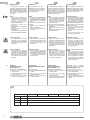 6
6
-
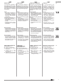 7
7
-
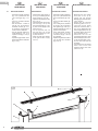 8
8
-
 9
9
-
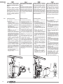 10
10
-
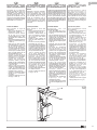 11
11
-
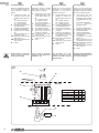 12
12
-
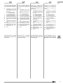 13
13
-
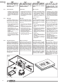 14
14
-
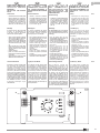 15
15
-
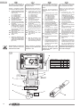 16
16
-
 17
17
-
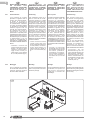 18
18
-
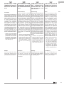 19
19
-
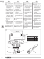 20
20
-
 21
21
-
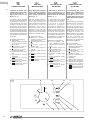 22
22
-
 23
23
-
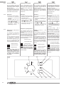 24
24
-
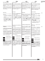 25
25
-
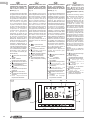 26
26
-
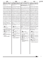 27
27
-
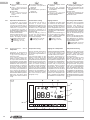 28
28
-
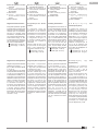 29
29
-
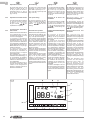 30
30
-
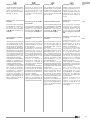 31
31
-
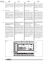 32
32
-
 33
33
-
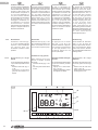 34
34
-
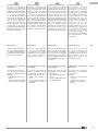 35
35
-
 36
36


Olimpia Splendid control - B0151-B0152 Benutzerhandbuch
- Typ
- Benutzerhandbuch
in anderen Sprachen
- English: Olimpia Splendid control - B0151-B0152 User manual
- français: Olimpia Splendid control - B0151-B0152 Manuel utilisateur
- español: Olimpia Splendid control - B0151-B0152 Manual de usuario
- italiano: Olimpia Splendid control - B0151-B0152 Manuale utente
- Nederlands: Olimpia Splendid control - B0151-B0152 Handleiding
- português: Olimpia Splendid control - B0151-B0152 Manual do usuário
Verwandte Papiere
-
 Olimpia Splendid Bi2 Wall Inverter Installationsanleitung
-
 Olimpia Splendid Bi2 SL Air Inverter Benutzerhandbuch
-
 Olimpia Splendid control - B0658 Benutzerhandbuch
-
 Olimpia Splendid control - B0659-B0673 Benutzerhandbuch
-
 Olimpia Splendid Bi2 B0828 Benutzerhandbuch
-
 Olimpia Splendid control - B0772 - B0774 Benutzerhandbuch
-
 Olimpia Splendid Condensate collection tray Kit B0520-B0521-B0522-B0523-B0524 Benutzerhandbuch
-
 Olimpia Splendid kit - B0643 Benutzerhandbuch
-
Olimpia Splendid control - B0152 Benutzerhandbuch
-
 Olimpia Splendid kit - B0685 Built-in control kit - B0686 Wall thermostat - B0736 Benutzerhandbuch


