Dometic RM8xxx, RMS8xxx, RML8xxx, RMSL8xxx Installationsanleitung
- Kategorie
- Kühlschränke
- Typ
- Installationsanleitung

REFRIGERATION
8 SERIES
RM8xxx, RMS8xxx, RML8xxx,
RMSL8xxx
Absorber refrigerator
Installation Manual
Absorber-Kühlschrank
Montageanleitung
EN
DE
title_16s_A4.fm Seite 1 Mittwoch, 15. Februar 2017 2:32 14


RM 8400 RM 8401 RM 8405 RM 8500 RM 8501 RM 8505 RM 8550 RM 8551 RM 8555
RMS 8400 RMS 8401 RMS 8405 RMS 8460 RMS 8461 RMS 8465 RMS 8500 RMS 8501
RMS 8505 RMS 8550 RMS 8551 RMS 8555 RML 8550 RML 8551 RML 8555 RMSL 8500
RMSL 8501 RMSL 8505
MBA 05/2012
N 1-1
Installation instructions
Absorption refrigerator for recreation vehicles
EN
English
289 0318-00_EN_RMx8xxx-Installation_N1-1.qxp 12.06.2012 07:35 Seite 1

© Dometic GmbH - 2011 - Subject to change without notice
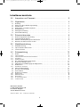
0.0 Unpacking and Transport . . . . . . . . . . . . . . . . . . . . . . . . . . . . . . . . 3
1.0 General . . . . . . . . . . . . . . . . . . . . . . . . . . . . . . . . . . . . . . . . . . . . . . 4
1.1 Introduction . . . . . . . . . . . . . . . . . . . . . . . . . . . . . . . . . . . . . . . . . . . . . . . . . . . . . . . . . . . . . . . . 4
1.2 Guide to these operating instructions . . . . . . . . . . . . . . . . . . . . . . . . . . . . . . . . . . . . . . . . . . . .4
1.3 Copyright protection . . . . . . . . . . . . . . . . . . . . . . . . . . . . . . . . . . . . . . . . . . . . . . . . . . . . . . . . . 4
1.4 Explanation of symbols used in this manual . . . . . . . . . . . . . . . . . . . . . . . . . . . . . . . . . . . . . . . 4
1.5 Warranty . . . . . . . . . . . . . . . . . . . . . . . . . . . . . . . . . . . . . . . . . . . . . . . . . . . . . . . . . . . . . . . . . . . 5
1.6 Limitation of liability . . . . . . . . . . . . . . . . . . . . . . . . . . . . . . . . . . . . . . . . . . . . . . . . . . . . . . . . . . 5
1.7 Declaration of conformity . . . . . . . . . . . . . . . . . . . . . . . . . . . . . . . . . . . . . . . . . . . . . . . . . . . . . . 5
2.0 Safety instructions . . . . . . . . . . . . . . . . . . . . . . . . . . . . . . . . . . . . . . 6
2.1 Application according to regulations . . . . . . . . . . . . . . . . . . . . . . . . . . . . . . . . . . . . . . . . . . . . .6
2.2 User's responsibility . . . . . . . . . . . . . . . . . . . . . . . . . . . . . . . . . . . . . . . . . . . . . . . . . . . . . . . . . . 6
2.3 Working upon and checking the refrigerator . . . . . . . . . . . . . . . . . . . . . . . . . . . . . . . . . . . . . . . 6
2.4 Operating the refrigerator with gas . . . . . . . . . . . . . . . . . . . . . . . . . . . . . . . . . . . . . . . . . . . . . . 6
3.0 Description of model . . . . . . . . . . . . . . . . . . . . . . . . . . . . . . . . . . . . 7
3.1 Model identification . . . . . . . . . . . . . . . . . . . . . . . . . . . . . . . . . . . . . . . . . . . . . . . . . . . . . . . . . . 7
3.2 Refrigerator rating plate . . . . . . . . . . . . . . . . . . . . . . . . . . . . . . . . . . . . . . . . . . . . . . . . . . . . . . . 7
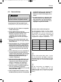
3.3 Technical data . . . . . . . . . . . . . . . . . . . . . . . . . . . . . . . . . . . . . . . . . . . . . . . . . . . . . . . . . . . . . . 7
4.0 Installation instructions . . . . . . . . . . . . . . . . . . . . . . . . . . . . . . . . . . 10
4.1 Installation . . . . . . . . . . . . . . . . . . . . . . . . . . . . . . . . . . . . . . . . . . . . . . . . . . . . . . . . . . . . . . . . . 10
4.1.1 Side installation . . . . . . . . . . . . . . . . . . . . . . . . . . . . . . . . . . . . . . . . . . . . . . . . . . . . . . . . . . . . . . . . . . . . . . 10
4.1.2 Side installation with floor-roof ventilation . . . . . . . . . . . . . . . . . . . . . . . . . . . . . . . . . . . . . . . . . . . . . . . . . 11
4.1.3 Rear installation . . . . . . . . . . . . . . . . . . . . . . . . . . . . . . . . . . . . . . . . . . . . . . . . . . . . . . . . . . . . . . . . . . . . . 11
4.1.4 Draught-proof installation . . . . . . . . . . . . . . . . . . . . . . . . . . . . . . . . . . . . . . . . . . . . . . . . . . . . . . . . . . . . . . 12
4.2 Ventilation and air extraction of the refrigerator . . . . . . . . . . . . . . . . . . . . . . . . . . . . . . . . . . . . 13
4.3 Installing the ventilation system . . . . . . . . . . . . . . . . . . . . . . . . . . . . . . . . . . . . . . . . . . . . . . . . . 14
4.4 Exhaust gas duct and installing the fume flue . . . . . . . . . . . . . . . . . . . . . . . . . . . . . . . . . . . . . . 15
4.5 Installation recess . . . . . . . . . . . . . . . . . . . . . . . . . . . . . . . . . . . . . . . . . . . . . . . . . . . . . . . . . . . . 16
4.5.1 Installation in the recess . . . . . . . . . . . . . . . . . . . . . . . . . . . . . . . . . . . . . . . . . . . . . . . . . . . . . . . . . . . . . . . 16
4.6 Securing the refrigerator . . . . . . . . . . . . . . . . . . . . . . . . . . . . . . . . . . . . . . . . . . . . . . . . . . . . . . 17
4.7 Inserting of the decor panel . . . . . . . . . . . . . . . . . . . . . . . . . . . . . . . . . . . . . . . . . . . . . . . . . . . . 17
4.8 Gas installation . . . . . . . . . . . . . . . . . . . . . . . . . . . . . . . . . . . . . . . . . . . . . . . . . . . . . . . . . . . . . . 19
4.9 Electrical installation . . . . . . . . . . . . . . . . . . . . . . . . . . . . . . . . . . . . . . . . . . . . . . . . . . . . . . . . . . 20
4.9.1 Mains connection . . . . . . . . . . . . . . . . . . . . . . . . . . . . . . . . . . . . . . . . . . . . . . . . . . . . . . . . . . . . . . . . . . . . 20
4.9.2 Battery connection . . . . . . . . . . . . . . . . . . . . . . . . . . . . . . . . . . . . . . . . . . . . . . . . . . . . . . . . . . . . . . . . . . . 20
4.9.3 Terminal strip . . . . . . . . . . . . . . . . . . . . . . . . . . . . . . . . . . . . . . . . . . . . . . . . . . . . . . . . . . . . . . . . . . . . . . . 21
4.9.4 D+ and solar connection (only for AES models) . . . . . . . . . . . . . . . . . . . . . . . . . . . . . . . . . . . . . . . . . . . . 21
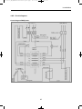
4.9.5 Wiring diagrams . . . . . . . . . . . . . . . . . . . . . . . . . . . . . . . . . . . . . . . . . . . . . . . . . . . . . . . . . . . . . . . . . . . . . 22
2
Table of contents
Dometic GmbH
In der Steinwiese 16
D-57074 Siegen
www.dometic.com
289 0318-00_EN_RMx8xxx-Installation_N1-1.qxp 12.06.2012 07:35 Seite 2

3
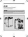
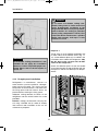
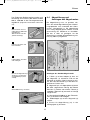
Lifting / carrying the refrigerator
0.0 Unpacking and Transport
Never use parts on the refrigerator other than those shown in the illustration (particularly
not the cooling unit, gas lines and control panel) for carrying or lifting the refrigerator !
This prevents damage to the refrigerator.
CAUTION!
NOT
OK
OK
OK
289 0318-00_EN_RMx8xxx-Installation_N1-1.qxp 12.06.2012 07:35 Seite 3

4
General
1.0 General
On installation of the appliance, the technical
and administrative regulations of the country
in which the vehicle will first be used must be
adhered to. Otherwise the refrigerator must be
installed as described in these instructions. In
Europe, for example, gas appliances, cable
routing, installation of gas cylinders, as well as
approval and checking for leaks must comply
with EN 1949 for liquid gas systems in vehi-
cles.
1.1 Introduction
Before you start installing the refrigerator,
please read the installation instructions
carefully.
These instructions provide you with the neces-
sary guidance for the proper installation of
your refrigerator. Observe in particular the
safety instructions. Observation of the
instructions and handling recommendations is
important for dealing with the refrigerator
safely and for protecting you from injury and
the refrigerator from damage. You must under-
stand what you have read before you carry out
a task.
Keep these instructions in a safe place
close to the refrigerator so they may be
referred to at any time.
1.2 Guide to these installation
instructions
The information, texts and illustrations in these
instructions are copyright protected and are
subject to industrial property rights.
No part of these instructions may be reprodu-
ced, copied or utilised in any other way wit-
hout written authorisation by Dometic GmbH,
Siegen.
1.3 Copyright protection
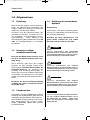
1.4 Explanation of symbols
used in this manual
Warning notices are identified by symbols. A
supplementary text gives you an explanation
of the degree of danger.
Observe these warning notices rigorously.
You will thus protect yourself and other
people from injury, and the appliance from
damage.
Warning notices
DANGER indicates an imminent hazardous
situation which, if not avoided, could result in
death or serious injury.
DANGER!
WARNING indicates a potentially hazardous
situation which, if not avoided, could result in
death or serious injury
WARNING!
WARNING indicates a potentially hazardous
situation which, if not avoided, could result in
death or serious injury
CAUTION!
CAUTION (used without the safety alert sym-
bol) indicates a potentially hazardous situation
which, if not avoided, may result in damage to
the appliance.
CAUTION!
289 0318-00_EN_RMx8xxx-Installation_N1-1.qxp 12.06.2012 07:35 Seite 4

5
General
All information and guidance in these opera-
ting instructions were prepared after taking
into consideration the applicable standards
and regulations as well as the current state of
the art. Dometic reserves the right to make
changes at any time which are deemed to be
in the interest of improving the product and
safety.
Dometic will assume no liability for damage in
the case of :
non-observation of the operating instructi-
ons
application not in accordance with the
regulations or provisions
use of non-original spare parts
modifications and interferences to the
appliance
effect of environmental influences, such as
- temperature fluctuations
- humidity
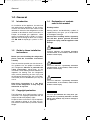
1.6 Limitation of liability
1.7 Declaration of conformity
Warranty arrangements are in accordance
with EC Directive 44/1999/CE and the normal
conditions applicable for the country concer-
ned. For warranty or other maintenance, plea-
se contact our customer services department.
Any damage due to improper use is not cover-
ed by the warranty. The warranty does not
cover any modifications to the appliance or
the use of non-original Dometic parts. The
warranty does not apply if the installation and
operating instructions are not adhered to and
no liability shall be entertained.
1.5 Warranty
Information
INFORMATION gives you supplementary and
useful guidance when dealing with your refrige-
rator.
Environmental Tips
ENVIRONMENTAL TIPS gives you useful gui-
dance for saving energy and disposal of the
appliance.
289 0318-00_EN_RMx8xxx-Installation_N1-1.qxp 12.06.2012 07:35 Seite 5

6
Safety instructions
2.0 Safety instructions
This refrigerator is designed for installation in
recreation vehicles such as caravans or
motorhomes. The appliance has been type-
approval tested for this application in accor-
dance with the EC Gas Directive.
The refrigerator is to be used solely for storing
foodstuffs.
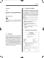
2.1 Application according to
regulations
2.3 Working upon and checking
the refrigerator
Work on gas equipment, exhaust system
and electrical facilities must be carried
out by authorised personnel only.
Substantial damage to property and/or
injury to persons can arise through unpro-
fessional procedures.
WARNING!
Never use an unshielded flame to check
gas bearing parts and pipes for leakage!
There is a danger of fire or explosion.
DANGER!
Never open the absorber cooling unit! It is
under high pressure.
There is a danger of injury!
WARNING!
Anyone operating the refrigerator must be
familiar with the safe handling and understand
the advice in these operating instructions.
2.2 User's responsibility
It is imperative that the operating pressure
corresponds to the data specified on the
rating plate of the appliance. Compare the
operating pressure of the rating plate with the
data specified on the pressure reducing valve
of the liquid gas cylinder.
2.4 Operating the refrigerator
with gas
The refrigerator must not be exposed to
rain.
CAUTION!
289 0318-00_EN_RMx8xxx-Installation_N1-1.qxp 12.06.2012 07:35 Seite 6

7
Description of model
Dometic refrigerators are equipped for a con-
nection pressure of 30 mbar. For connection
to a 50 mbar gas system, use Truma VDR
50/30 medium pressure controller.
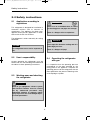
3.0 Description of model
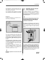
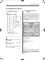
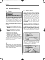
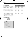
3.1 Model identification
The rating plate is to be found on the inside of
the refrigerator. It contains all important details
of the refrigerator. You can read off from this
the model identification, the product number
and the serial number. You will need these
details whenever you contact the customer
service centre or when ordering spare parts.
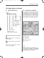
3.2 Refrigerator rating plate
Model number
Product number
Serial number
Electrical rating details
Gas pressure
2
1
3
4
5
RM
8 4 0 0
1
5
(S)
(L)
Refrigerator Mobile /
Mobile Absorption Refrigerator
Model range
4 = Width 486mm
5 = Width 523mm
Depth:
0 = Standard
5 = + 55mm
6 = + 65mm
Stepped cabinet
„Large“
Example :
0
manual energy selection + manual ignition
(battery igniter)
1
manual energy selection, automatic ignition
(MES)
5
automatic and manual energy selection,
automatic ignition (AES)
Fig. 1
Example
2
1
3
4
5
289 0318-00_EN_RMx8xxx-Installation_N1-1.qxp 12.06.2012 07:35 Seite 7

8
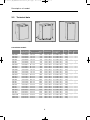
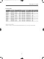
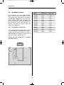
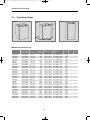
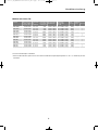
3.3 Technical data
Description of model
Fig. 3Fig. 2
RMS 8xxx
RM 8xxx
H
W
D
RML 8xxx
Fig. 4
Model Dimensions Gross capacity
Rating details
Consumption * Net Ignition
H x W x D (mm) with without mains/battery electricity/gas weight Piezo Automat
Depth incl. door freezer compartment over 24hrs
RMS 8400
RMS 8401
RMS 8405
RM 8400
RM 8401
RM 8405
RMS 8460
RMS 8461
RMS 8465
RMS 8500
RMS 8501
RMS 8505
RMS 8550
RMS 8551
RMS 8555
RM 8500
RM 8501
RM 8505
RM 8550
RM 8551
RM 8555
RML 8550
RML 8551
RML 8555
RMSL 8500
RMSL 8501
RMSL 8505
821x486x568
821x486x568
821x486x568
821x486x568
821x486x568
821x486x568
821x486x633
821x486x633
821x486x633
821x523x568
821x523x568
821x523x568
821x523x623
821x523x623
821x523x623
821x523x568
821x523x568
821x523x568
821x523x623
821x523x623
821x523x623
1245x523x625
1245x523x625
1245x523x625
1245x523x568
1245x523x568
1245x523x568
80 / 8 lit.
80 / 8 lit.
80 / 8 lit.
90 / 8 lit.
90 / 8 lit.
90 / 8 lit.
90 / 11 lit.
90 / 11 lit.
90 / 11 lit.
90 / 9 lit.
90 / 9 lit.
90 / 9 lit.
103 /12 lit.
103 /12 lit.
103 /12 lit.
100 / 9 lit.
100 / 9 lit.
100 / 9 lit.
115 /12 lit.
115 /12 lit.
115 /12 lit.
179 /33 lit.
179 /33 lit.
179 /33 lit.
145 /28 lit.
145 /28 lit.
145 /28 lit.
25 kg
25 kg
25 kg
27 kg
27 kg
27 kg
26 kg
26 kg
26 kg
26 kg
26 kg
26 kg
27 kg
27 kg
27 kg
28 kg
28 kg
28 kg
30 kg
30 kg
30 kg
45 kg
45 kg
45 kg
40 kg
40 kg
40 kg
85 lit.
85 lit.
85 lit.
95 lit.
95 lit.
95 lit.
96 lit.
96 lit.
96 lit.
96 lit.
96 lit.
96 lit.
110 lit.
110 lit.
110 lit.
106 lit.
106 lit.
106 lit.
122 lit.
122 lit.
122 lit.
189 lit.
189 lit.
189 lit.
155 lit.
155 lit.
155 lit.
125 W / 120 W
125 W / 120 W
125 W / 120 W
135 W / 130 W
135 W / 130 W
135 W / 130 W
125 W / 120 W
125 W / 120 W
125 W / 120 W
125 W / 120 W
125 W / 120 W
125 W / 120 W
125 W / 120 W
125 W / 120 W
125 W / 120 W
135 W / 130 W
135 W / 130 W
135 W / 130 W
135 W / 130 W
135 W / 130 W
135 W / 130 W
190 W / 170 W
190 W / 170 W
190 W / 170 W
190 W / 170 W
190 W / 170 W
190 W / 170 W
•
•
•
•
•
•
•
•
•
•
•
•
•
•
•
•
•
•
•
•
•
•
•
•
•
•
•
ca.2,5 KWh / 270 g
ca.2,5 KWh / 270 g
ca.2,5 KWh / 270 g
ca.2,4 KWh / 270 g
ca.2,4 KWh / 270 g
ca.2,4 KWh / 270 g
ca.2,5 KWh / 270 g
ca.2,5 KWh / 270 g
ca.2,5 KWh / 270 g
ca.2,5 KWh / 270 g
ca.2,5 KWh / 270 g
ca.2,5 KWh / 270 g
ca.2,6 KWh / 270 g
ca.2,6 KWh / 270 g
ca.2,6 KWh / 270 g
ca.2,4 KWh / 270 g
ca.2,4 KWh / 270 g
ca.2,4 KWh / 270 g
ca.2,6 KWh / 270 g
ca.2,6 KWh / 270 g
ca.2,6 KWh / 270 g
ca.3,2 KWh / 380 g
ca.3,2 KWh / 380 g
ca.3,2 KWh / 380 g
ca.3,2 KWh / 380 g
ca.3,2 KWh / 380 g
ca.3,2 KWh / 380 g
Curved door models
289 0318-00_EN_RMx8xxx-Installation_N1-1.qxp 12.06.2012 07:35 Seite 8

9
Description of model
Subject to technical changes.
*Average consumption measured at an average ambient temperature of 25°C in pursuance of ISO Standard.
Model Dimensions Gross capacity
Rating details
Consumption * Net Ignition
H x W x D (mm) with without mains/battery electricity/gas weight Piezo Automat
Depth incl. door freezer compartment over 24hrs
RMS 8500
RMS 8501
RMS 8505
RMS 8550
RMS 8551
RMS 8555
RM 8500
RM 8501
RM 8505
RM 8550
RM 8551
RM 8555
821x523x541
821x523x541
821x523x541
821x523x596
821x523x596
821x523x569
821x523x541
821x523x541
821x523x541
821x523x596
821x523x596
821x523x596
86 / 9 lit.
86 / 9 lit.
86 / 9 lit.
99 /12 lit.
99 /12 lit.
99 /12 lit.
96 / 9 lit.
96 / 9 lit.
96 / 9 lit.
111 /12 lit.
111 /12 lit.
111 /12 lit.
26 kg
26 kg
26 kg
27 kg
27 kg
27 kg
28 kg
28 kg
28 kg
30 kg
30 kg
30 kg
92 lit.
92 lit.
92 lit.
106 lit.
106 lit.
106 lit.
102 lit.
102 lit.
102 lit.
118 lit.
118 lit.
118 lit.
125 W / 120 W
125 W / 120 W
125 W / 120 W
125 W / 120 W
125 W / 120 W
125 W / 120 W
135 W / 130 W
135 W / 130 W
135 W / 130 W
135 W / 130 W
135 W / 130 W
135 W / 130 W
•
•
•
•
•
•
•
•
•
•
•
•
ca.2,5 KWh / 270 g
ca.2,5 KWh / 270 g
ca.2,5 KWh / 270 g
ca.2,6 KWh / 270 g
ca.2,6 KWh / 270 g
ca.2,6 KWh / 270 g
ca.2,4 KWh / 270 g
ca.2,4 KWh / 270 g
ca.2,4 KWh / 270 g
ca.2,6 KWh / 270 g
ca.2,6 KWh / 270 g
ca.2,6 KWh / 270 g
Flat door models
289 0318-00_EN_RMx8xxx-Installation_N1-1.qxp 12.06.2012 07:35 Seite 9

10
Installation
4.0 Installation instructions
The unit and the exhaust duct system must be
in principle installed so that it is accessible for
maintenance work, can be easily installed and
dismantled and removed from the vehicle wit-
hout great effort.
Installation and connection of the appliance
must comply with the latest technical regulati-
ons, as follows:
The electrical installation must comply
with national and local regulations.
The gas installation must comply with
national and local regulations.
European Standard EN 1949
European Standards EN 60335-1,
EN 60335-2-24, EN 1648-1 , EN 1648-2
The appliance must be installed in such
a way that it is shielded from excessive
heat radiation.
Excessive heat impairs performance and rai-
ses the energy consumption of the refrigera-
tor!
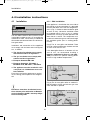
4.1 Installation
Deviations from these installation instruc-
tions without prior notification of Dometic
result in Dometic GmbH's warranty obliga-
tions becoming void!
The appliance may be installed by authori-
sed personnel only!
WARNING!
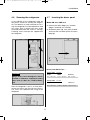
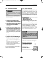
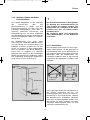
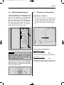
(Fig. 6) The air vent grilles offer an unobstruc-
ted dissipation of heat and exhaust gas even
when the door is opened.
4.1.1 Side installation
If the appliance is installed on the same side of
the vehicle as the entrance door, it is desirable
that the door does not cover the refrigerator's
vents. (Fig. 5, Clearance door/ventilation grille
at least 25 mm). Otherwise ventilation could
be impaired which causes a loss in cooling
performance. Awnings are often placed at the
door side of a caravan. This complicates eva-
cuation of combustion gases and heat through
the ventilation grilles (loss in cooling perfor-
mance)!
(Fig.5) The air vent grilles are blocked. There
must be a distance between the door and the
air vents of at least 25 mm!
If the door/grille distance is between 25 mm
and 45 mm, we recommend installing a
Dometic ventilation kit (
item no. 241 2985 -
00/0
) to achieve an optimal cooling perfor-
mance in high ambient temperatures.
Fig. 5
Fig. 6
Air vent grille not-
blocked! OK!
289 0318-00_EN_RMx8xxx-Installation_N1-1.qxp 12.06.2012 07:35 Seite 10

11
Installation
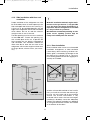
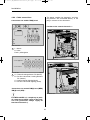
Fig. 7
floor opening:
at least 50 mm wide,
at least 520 mm long
hot air
condenser
Recommendation:
Roof vent
R500
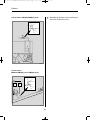
Proper ventilation of the refrigerator can also
be achieved by lower air intake aperture in the
floor and upper roof exhaust vent (see Fig. 7).
A flue has to be provided between the top
edge of the refrigerator and the roof ventilation
which directs the hot air and the exhausts
straight to the air vent in the roof.
The floor opening must have a cross section of
at least 250 cm² . Protect the opening, e.g.
with a baffle plate and a net, to prevent dirt
from entering the gas burner. Compared to
side ventilation, this ventilation method can
allow more dirt to enter the rear area of the
refrigerator, which makes regular maintenance
of the gas burner, at least once a year, neces-
sary.
With this installation method, regular main-
tenance of the gas burner is only possible
once the device has been dismantled. It is
imperative that the refrigerator be installed
in a way to allow easy removal.
We therefore recommend providing an ade-
quate access opening (service flap) for
ready serviceability from the outside.
4.1.2 Side installation with floor-roof
ventilation
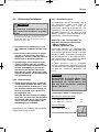
Another unfavourable method of rear installa-
tion is to install the air intake and exhaust gril-
les (Fig. 10) at the side wall of the recreation
vehicle. The air-heat recirculation is very
restricted which means that heat exchangers
(condenser, absorber) cannot be adequately
cooled. The optional method of an additional
air vent grille installed in the floor also exhibits
an insufficient air flow duct.
Fig. 8
Fig. 9
Air vent grille not
blocked ! OK!
Air vent grille
blocked !
4.1.3 Rear installation
Rear installation often causes an unfavourable
installation arrangement, as ideal ventilation
cannot always be assured (e.g. the lower ven-
tilation grille is covered by the bumper or the
rear lights of the vehicle!) (Fig. 8). The maxi-
mum cooling performance of the aggregate is
actually not available.
289 0318-00_EN_RMx8xxx-Installation_N1-1.qxp 12.06.2012 07:35 Seite 11

12
Fig. 10
The maximum cooling performance is not
available! Do not apply this installation
method, as it does not provide proper ven-
tilation! Please refer to the description in
section 4.2 .
CAUTION!
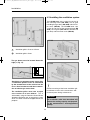
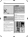
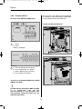
4.1.4 Draught-proof installation
Refrigerators in motorhomes, caravans or
other vehicles must be installed in a draught-
proof manner (EN 1949). This means that the
combustion air for the burner is not taken from
the living space and that exhaust fumes are
prevented from entering the living space.
Adequate sealing between the back of the
refrigerator and the vehicle interior has to be
provided.
Dometic strongly recommends carrying this
out using a flexible seal (in order to simplify
later removal and installation of the unit for
maintenance purposes.
By no means use durable sealing com-
pounds, fitting foam or similar material to
realise draught-proof installation of the
refrigerator! Do NOT use any easily inflam-
mable materials for sealing (in particular
silicon sealing compound or similar). Risk
of fire! The device manufacturer's product
liability and warranty shall lapse if such
materials are used.
WARNING!
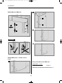
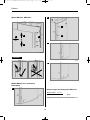
The lip seals (1) are installed at the bottom and
on each side in the installation recess (Fig. 11-
13). A heat deflector plate (2) is installed in the
installation recess above the refrigerator. Affix
the this plate to the caravan wall, do NOT
attach to the refrigerator !
Attach the deflector plate so that the heated
air escapes through the top ventilation grill into
the open air and no heat build-up can be pro-
duced.
Fig. 12
Fig. 11
Fig. 13
1
1
2
2
Proposal 1
Installation
289 0318-00_EN_RMx8xxx-Installation_N1-1.qxp 12.06.2012 08:49 Seite 12

13
The cavity in-between the outer vehicle wall
and refrigerator is completely isolated from the
vehicle interior. Intrusion of exhaust fumes into
the living space is prevented. Fumes will esca-
pe through the upper ventilation grille to the
outside.
The draught-proof installation does not requi-
re a special exhaust gas duct to be used. This
installation method allows the use of the same
air vent grille LS200 at the top and at the bot-
tom without flue duct. .-Nummer :
If a flue duct is nevertheless desirable, incor-
porate the LS100 ventilation system with flue
duct into the upper air vent opening. (
For
installation, please refer to "4.4"
)
Deviations require the consent of the manu-
facturer!
In the event of high ambient temperatures,
full performance of the cooling unit can
only be achieved by means of adequate
ventilation and extraction.
A correct installation of the refrigerator is
essential for its correct operation, as due to
physical reasons heat builds up at the back of
the appliance which must be allowed to esca-
pe into the open air.
4.2 Ventilation and air extracti-
on of the refrigerator
The refrigerator is later pushed into the instal-
lation recess from the front. Ensure that the
seals abut the case evenly.
This installation option facilitates the removal
and installation of the appliance for servicing.
Fig. 14
Fasten the sealing lips to a stop bar on the
rear side (1), e.g. by gluing.
1
Proposal 2
Installation
Ventilation is provided for the unit by means of
two apertures in the caravan wall. Fresh air
enters at the bottom, extracts the heat and
exits through the upper vent grille (chimney
effect).
The upper ventilation grille should be posi-
tioned as high as possible above the con-
denser (1, , Fig.16). Install the lower ventila-
tion grille at floor level of the recess (Fig.
16,17), allowing unburnt gas (heavier than air)
to escape directly into the open air.
Fig. 15
289 0318-00_EN_RMx8xxx-Installation_N1-1.qxp 12.06.2012 07:36 Seite 13

14
Correct mounting of the lower ventilation gril-
le facilitates access to the connections and
functional parts during maintenance.
Fig. 18
Fig. 19
The LS 100 upper vent system kit consists of
the mounting frame (RS 1640), the air grille
including flue gas duct (AS 1620) and the win-
ter cover (WA120). The LS 200 lower vent
system kit consists of the mounting frame (RS
1650), the air grille (AS1 630, but without flue
gas duct) and the winter cover (WA130).
4.3 Installing the ventilation system
LS 100
LS 200
1
2
3
4
Installation
Fig. 16
1
2
1
2
Ventilation grille LS 100 or LS 200
Ventilation grille LS 200
2
1
Should this arrangement prove impossible,
a ventilation aperture must be introduced
by the manufacturer of the vehicle into the
recess floor in order to avoid the accumula-
tion of unburnt gas on the floor.
The ventilation grilles must have an open
cross-section of at least 250cm². This is
achieved by using the Dometic LS100/LS 200
absorber ventilation and air extraction system
which has been tested and approved for this
purpose.
Fig. 17
1
The gas burner must be located above the
edge (1, Fig. 17).
An installation other than described will
reduce the cooling capacity and jeopardi-
se the manufacturer's warranty/product
liability.
CAUTION!
289 0318-00_EN_RMx8xxx-Installation_N1-1.qxp 12.06.2012 07:36 Seite 14

15
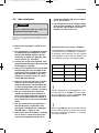
Fig. 20
Fig. 24
Seal the mounting frame
making it waterproof
(
does not apply for
mounting frames with
integral seal
).
1
Fig. 21
Insert frame and screw
into position
2
To install the ventilation grilles, cut two rectan-
gles (451 mm x 156 mm) in the outer wall of
the vehicle (
for position of the cuts, see point
4.2
).
Fig. 22
Insert and lock ventilati-
on grille.
3
Fig. 23
Clip the insert for flue
gas duct in position (
only
for L100 upper ventilati-
on system kit
).
4
Insert winter cover.
5
Installation
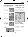
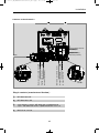
The exhaust gas duct system must be made in
such a manner as to achieve a complete
extraction of combustion products to the out-
side of living space. The duct system must
slope in an upward direction in order to avoid
a build-up of condensate. The type of exhaust
gas duct shown in Fig. 25 allows the installati-
on of the winter cover next to (10) (Fig. 25).
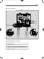
4.4 Exhaust gas duct and instal-
ling the fume flue
Installing the standard fume flue
1. Connect T-piece (1) to adaptor (2) or flue
pipe (3) as required and affix with screw (4).
Ensure that heat baffle (5) is lodged in the cor-
rect position.
2. Insert flue pipe with cover plate (6) through
the appropriate aperture in the upper frame (7)
and connect to T-piece (1). If necessary, shor-
ten flue pipe (6) to the required length.
3. Insert and lock ventilation grill LS 100 (8) in
the mounting frame (7).
4. Put cap (9) on flue pipe (6).
5. Insert extractor insert (10) into ventilation
grille (8) .
Fig. 25
1
2
3
4
5
6 79
10
8
min. 15mm
289 0318-00_EN_RMx8xxx-Installation_N1-1.qxp 12.06.2012 07:36 Seite 15

16
Installation
Model Height H
ST
Depth T
ST
RMS 8400
RMS 8401
RMS 8405
RMS 8460
RMS 8461
RMS 8465
RMS 8500
RMS 8501
RMS 8505
RMS 8550
RMS 8551
RMS 8555
RMSL 8550
RMSL 8551
RMSL 8555
220 mm
220 mm
220 mm
220 mm
220 mm
220 mm
220 mm
220 mm
220 mm
220 mm
220 mm
220 mm
220 mm
220 mm
220 mm
235 mm
235 mm
235 mm
235 mm
235 mm
235 mm
235 mm
235 mm
235 mm
235 mm
235 mm
235 mm
235 mm
235 mm
235 mm
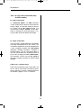
Push the appliance far enough into the recess
until the front edge of the refrigerator casing is
aligned with the front of the recess. Allow a
gap of 15-20 mm between the back wall of
the recess and the refrigeration unit.
Ensure that the refrigerator is installed
level in the recess.
The refrigerator must be installed draught-
proof in a recess (also refer to Section "4.1.4").
The measurements of the recess are stated in
the table below. Step (1) (Fig. 26) is only requi-
red for cabinets with a step. The floor of the
recess must be level, allowing the appliance to
be pushed easily into its correct position. The
floor must be substantial enough to bear the
weight of the appliance.
4.5 Installation recess
Fig. 26
T
ST
min
15-20mm
H
ST
1
4.5.1 Installation in the recess
289 0318-00_EN_RMx8xxx-Installation_N1-1.qxp 12.06.2012 07:36 Seite 16

17
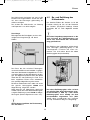
After the refrigerator is put in its final place,
secure the screws into the wall of the recess.
The screws must penetrate the casing of the
refrigerator.
Fig. 27
Fig. 28
In the sidewalls of the refrigerator, there are
four plastic sleeves for securing the refrigera-
tor. The sidewalls or strips attached for secu-
ring the refrigerator must be prepared to hold
the screws firmly in place even when under
increased load (while the vehicle is moving).
Fastening screws and caps are supplied with
the refrigerator
4.6 Securing the refrigerator
Always insert screws through the sleeves
provided as otherwise components laid in
foam, such as cables etc., could be dama-
ged.
CAUTION!
4.7 Inserting the decor panel
Remove the lateral ledge (1) the door
(ledge is attached, not screwed).
Shift decor panel (2) away from the door
and insert the new decor panel. Re-attach
ledge (1).
Fig. 29
Model RM 8xxx, RMS 8xxx
Decor panel dimensions :
743 +/- 0.5 mm 472 +/- 0.5 mm max. 2.2 mm
Casing width
486 mm
Height Width Thickness
743 +/- 0.5 mm 510.5 +/- 0.5 mm max. 2.2 mm
Casing width
523 mm
Height Width Thickness
2
1
Installation
289 0318-00_EN_RMx8xxx-Installation_N1-1.qxp 12.06.2012 07:36 Seite 17

18
Installation
Fig. 31
Fig. 32
Decor panel dimensions RML 8xxx :
1169,5 +0/-1 mm 507,5 +0/-1 mm max. 1.7 mm
Casing width
523 mm
Height Width Thickness
CAUTION!
Fig. 30
1
2
1.
2.
3.
4.
Model RM 8xxx, RMS 84xx
Fig. 35
Fig. 36
Fig. 34
Model RMx(L) 8xxx, frameless decor
panel
1
2
3
4
1.
2.
Fig. 33
289 0318-00_EN_RMx8xxx-Installation_N1-1.qxp 12.06.2012 07:36 Seite 18
Seite wird geladen ...
Seite wird geladen ...
Seite wird geladen ...
Seite wird geladen ...
Seite wird geladen ...
Seite wird geladen ...
Seite wird geladen ...
Seite wird geladen ...
Seite wird geladen ...
Seite wird geladen ...
Seite wird geladen ...
Seite wird geladen ...
Seite wird geladen ...
Seite wird geladen ...
Seite wird geladen ...
Seite wird geladen ...
Seite wird geladen ...
Seite wird geladen ...
Seite wird geladen ...
Seite wird geladen ...
Seite wird geladen ...
Seite wird geladen ...
Seite wird geladen ...
Seite wird geladen ...
Seite wird geladen ...
Seite wird geladen ...
Seite wird geladen ...
Seite wird geladen ...
Seite wird geladen ...
Seite wird geladen ...
Seite wird geladen ...
Seite wird geladen ...
Seite wird geladen ...
Seite wird geladen ...
Seite wird geladen ...
Seite wird geladen ...
Seite wird geladen ...
Seite wird geladen ...
Seite wird geladen ...
Seite wird geladen ...
-
 1
1
-
 2
2
-
 3
3
-
 4
4
-
 5
5
-
 6
6
-
 7
7
-
 8
8
-
 9
9
-
 10
10
-
 11
11
-
 12
12
-
 13
13
-
 14
14
-
 15
15
-
 16
16
-
 17
17
-
 18
18
-
 19
19
-
 20
20
-
 21
21
-
 22
22
-
 23
23
-
 24
24
-
 25
25
-
 26
26
-
 27
27
-
 28
28
-
 29
29
-
 30
30
-
 31
31
-
 32
32
-
 33
33
-
 34
34
-
 35
35
-
 36
36
-
 37
37
-
 38
38
-
 39
39
-
 40
40
-
 41
41
-
 42
42
-
 43
43
-
 44
44
-
 45
45
-
 46
46
-
 47
47
-
 48
48
-
 49
49
-
 50
50
-
 51
51
-
 52
52
-
 53
53
-
 54
54
-
 55
55
-
 56
56
-
 57
57
-
 58
58
-
 59
59
-
 60
60


Dometic RM8xxx, RMS8xxx, RML8xxx, RMSL8xxx Installationsanleitung
- Kategorie
- Kühlschränke
- Typ
- Installationsanleitung
in anderen Sprachen
Verwandte Artikel
-
Dometic RMS 8501 Bedienungsanleitung
-
Dometic RM8xxx, RMS8xxx, RML8xxx, RMSL8xxx Installationsanleitung
-
-
Dometic RMD 8501 Bedienungsanleitung
-
-
-
-
-
-