BSVILLAGE Azuro 6m3/h + Timer Installation, Assembly And Operation Manual
- Kategorie
- Oberirdisches Poolzubehör
- Typ
- Installation, Assembly And Operation Manual
Dieses Handbuch eignet sich auch für

MANUALE di MONTAGGIO
Filtro a sabbia
monoblocco AZURO
www.bsvillage.com


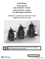
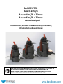
Sand Filters
Azuro 2m
3
/h
Azuro 4m
3
/h + Timer
Azuro 6m
3
/h + Timer
for above-ground pools
Installation, assembly and operation manual
(original instruction manual)
PRIOR TO INSTALLING AND USING THIS PRODUCT, THOROUGHLY READ,
UNDERSTAND AND ADHERE ALL THE INSTRUCTIONS IN THE MANUAL.
KEEP THE MANUAL FOR LATER REFERENCE.
Version 1/ March 2020

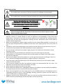
Safety Instructions
This symbol marks instructions if failure to comply can endanger personal health.
This symbol marks instructions if failure to comply can result in electrical shock injuries.
WHEN SWIMMING IN THE POOL OR
HANDLING IT IN ANY WAY, DISCONNECT
THE APPLIANCE FROM THE POWER
SUPPLY.
READ AND OBSERVE ALL INSTRUCTIONS.
Failure to comply with the instructions in this manual can result in injuries or even
death caused by electric shock.
This appliance may be used by children 8 years of age and older and by persons with reduced
physical, sensory or mental abilities or lack of experience and knowledge if they have been
supervised or instructed in the safe use of the appliance and understand the resulting hazards.
Children may not play with the appliance. Cleaning and user maintenance shall not be made by
children without supervision.
Make sure the appliance’s power supply complies with the related ČSN standards, is at least 3.5 m
from the pool and protected by a residual current device with tripping current of no more than 30
mA.
The device is to be connected directly to the electrical socket. When using an extension, only use
an extension that complies with ČSN standards for exterior applications.
Do not attempt to disconnect the power supply plug from the socket with wet hands or when
standing in water.
Place the device so that children won’t be able to use it as a tool to get into the pool.
Keep children at a safe distance from the device and the power cord. Make sure children won’t
play with the appliance
Do not dig the power cord of the appliance is into the ground (to prevent its damage). Place it so
that it cannot be damaged by lawnmowers, hedge trimmers or similar tools.
Leave the power cords accessible only to the maintenance personnel (in case the power supply
needs to be disconnected).
Prior to persons people the pool, the appliance needs to be disconnected from the mains. The
appliance may not be used if there are people in the pool
Never operate the appliance without any water.
Never operate the appliance if it’s damaged or defective. Any defects are to be rectified immediately.
Use original spare parts for maintenance and repair purposes.
Never turn the appliance on if the six-way valve is in the CLOSED position or if the pipeline circuit is
impassable; otherwise, there is a risk of damage, breaking, rupture or avulsion of its lid, which can
result in bodily harm or property damage.
Regularly check the filter sedimentation status, an clean the pre-filter and the skimmer basket in
order to prevent pump damage and ensure proper system functioning.

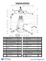
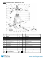
Component list – AZURO 2m
3
/h
Item Name Quantity Item Name Quantity
1 Multiport valve 1 14 Suction pipe 1
2 Plug 2 15 Suction basket 1
3 Flat lid gasket 2 16 Suction basket bottom 1
4 Flat pressure gauge gasket 1 17 Vessel 1
5 Pressure gauge 1 18 Hopper 1
6
Valve sleeve 1/2, incl.
connection materials
2 19 Base with pump 1
7
Shaped arbour and elbow
gaskets
4 20 Pre-filter 1
8 Shaped arbour and elbow nuts 4 21 Pool hose – 3 parts 2
9 Elbow D38 2 22 Hose clamp 25-40 4
10 Hose clamp 40-60 2 23 Waste set 1
11 Arbour D32/38 2 24 Flat prefilter gasket 1
12 Interconnecting hoses 1 25 Teflon band 1
13 Drainage strainer 1 26
Foreign body intrusion
prevention grate
1

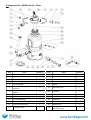
Component list – AZURO 4m
3
/h + Timer
Item Name Quantity
Item Name Quantity
1 Multiport valve 1
14 Suction pipe 1
2 Plug 1
15 Suction basket 1
3 Flat lid gasket 1
16 Suction basket bottom 1
4 Flat pressure gauge gasket 1
17 Vessel 1
5 Pressure gauge 1
18 Hopper 1
6
Valve sleeve 1/2, incl. connection
materials
2
19 Base with pump 1
7
Shaped arbour and
elbow
gaskets
4
20 Pre-filter 1
8 Shaped arbour and elbow nuts 4
21 Pool hose – 3 parts 2
9 Elbow D38 2
22 Hose clamp 25–40 4
10 Hose clamp 40–60 2
23 Waste set 1
11 Arbour D32/38 2
24 Flat prefilter gasket 1
12 Interconnecting hoses 1
25 Teflon band 1
13 Drainage bolting 1
26
Foreign body intrusion
prevention grate
1

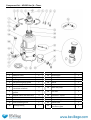
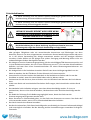
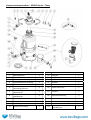
Component list – AZURO 6m
3
/h + Timer
Item Name Quantity
Item Name Quantity
1 Multiport valve 1
13 Suction pipe 1
2 Plug 1
14 Suction basket 1
3 Flat lid gasket 1
15 Suction basket bottom 1
4 Flat pressure gauge gasket 1
16 Vessel 1
5 Pressure gauge 1
17 Hopper 1
6
Valve sleeve 1/2, incl.
connection materials
2
18 Base with pump 1
7
Shaped arbour and elbow
gaskets
3
19 Pre-filter 1
8 Shaped arbour and elbow nuts 4
20 Pool hose – 3 parts 2
9 Elbow D38 4
21 Waste set 1
10 Hose clamp 40–60 6
22 Flat prefilter gasket 1
11 Interconnecting hoses 1
23 Teflon band 1
12 Drainage bolting 1
24
Foreign body intrusion
prevention grate
1

Purpose
This filtering unit is intended for water filtering in seasonal above-ground pools. It is not intended for pools
operated throughout the year. The filtering pump is not self-suction, which is why the filtering needs to be
installed below the water level in the pool, with natural watering.
WARNING: The depictions in this manual are merely illustrative and can differ from the actual product. We reserve
the right to alter the product partially or completely without prior notice.
Filtering unit usage conditions:
- water pH of 6–8.5
- max. chlorine content of 10 mg/l
- max salt content of 0.5%
Prior to Commissioning
Prior to the completion and commissioning of the appliance, unpack all of its components.
Keep the filtering equipment at a safe distance from its surroundings (allowing safe operation).
The filtering equipment needs to be positioned on a platform (such as a concrete boards etc.). The platform should
be laid and levelled using a spirit level. The appliance should not be standing in grass, as it could overheat.
Make sure the appliance does not get flooded. Flooding could be damage the machine or expose people to danger
of electrical shock.
If the pool has already been partially or completely filled, you need to position the filtering appliance into a
filtering shaft, which will be interconnected with the pool. If your filtering equipment has been placed in the shaft,
make sure the shaft cannot be flooded with water. In order to prevent the flooding, it is recommended that you
gravel it (so that small amounts of water are absorbed) and create a direct sewer drainage. It is important to
ensure good ventilation for the shaft, otherwise the appliance may be damaged due to water condensation.
The required accessories, such as more hoses, hose clamps and filtering sand (not included in the delivery) are
available from the vendor.
Must not be dry-operated (with no water)!!! Using the filtering equipment in such way
voids the warranty.
Technical Data
AZURO 2m³/h AZURO 4m³/h + Timer AZURO 6m³/h + Timer
Voltage 230 V / 50 Hz 230 V / 50 Hz 230 V / 50 Hz
Power consumption 85 W 190 W 250 W
System flow-through 2 m
3
/h 4 m
3
/h 5.5 m
3
/h
Protection class IP X5 IP X5 IP X5
Discharge 1.5 m 1.5 m 1.5 m
Filter diameter 143 mm 143 mm 143 mm
Effective filtering surface 0.036 m
2
0.036 m
2
0.036 m
2
Operating pressure 0.2 bar 0.3 bar 0.5 bar
Maximum working pressure 0.4 bar 0.6 bar 1.0 bar
Maximum water temperature
35 °C 35 °C 35 °C
Sand load 10 kg 14 kg 18 kg
Granularity 0.6 - 1.2 mm 0.6 - 1.2 mm 0.6 - 1.2 mm
Protect the environment!
Do NOT dispose of this product with household waste. The product
contains electrical/electronic components. Pursuant to the European directive 2012/19/EU,
electrical and electronic devices may not be disposed of as communal waste – it is necessary to turn
them in for environmentally friendly disposal at dedicated collection points. Information about these
points are available at your city hall.

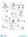
Assembly
Note: Since all connections have gaskets, there is no need to tighten the nuts too much. This could damage plastic
parts.
Note: You’ll need a cross-point screwdriver for the assembly.
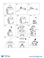
1. Mounting of the drainage bolting into the vessel.
Put the threaded counterpart through the vessel’s drainage opening from the inside (FIG. 1.1). Put a gasket
over the protruding thread and screw the socket on (FIG. 1.2). Put the sand strainer into it. Push the strainer inside
by screwing on the lid with the sealing O-ring (FIG. 1.3). Hand-tightening is sufficient for connection sealing. You
might damage the parts if you use pliers.
1.A For 10L vessels with drainage sockets, proceed as follows:
Put the drainage strainer through the vessel’s drainage opening from the inside (FIG. 1.4). Screw the lid with
a gasket onto the socket (OBR 1.5). Hand-tightening is sufficient for connection sealing. You might damage the
parts if you use pliers.
2. Suction basket completion
Connect the basket bottom to the suction basket itself by snapping in the 6 locks around its circumference.
Put a suction pipe into the completed suction basket (FIG. 2.1). Put the unit into the empty vessel (FIG. 2.2) and
fix its position by putting the hopper on (FIG. 2.3). The vessel is now ready for filling.
3. Filling with Sand
Prior to the filling, we recommend that you put the vessel onto the pump platform. The filled vessel is difficult
to handle. Fit the vessel side skims with the skims in the stand; the drainage bolting must point away from the
switch (FIG. 3.1).
With the hopper put on, fill the vessel with a required amount of sand (FIG. 3.2). The sand level in the vessel
should be reaching the top of the side skims (FIG. 3.3). Afterwards, take the hopper off and remove grains of sand
and other impurities from the sealing surface of the vessel socket.
4. Multiport Valve Installation
Put an O-ring through the bottom of the valve and put the valve onto the socket of the filled vessel. Direct the
valve so that its PUMP/ČERP socket is pointing in the same direction as the pump outlet in the vessel stand.
Afterwards, put both sleeve halves onto the vessel recess, connect with bolts (FIG. 4.3) and tighten evenly.
Insert a small rubber gasket into the pressure gauge opening, screw the pressure gauge body (FIG. 4.1) on
with your hand and tighten lightly.
!!! Make sure the screwing is done properly; otherwise, you may damage the fine thread!!!
Screw the lid with a gasket onto the WASTE/ODPAD port (OBR 4.2).
5. Connection Hose Installation
Put the constraining clamps onto the hose, put elbows with swivel nuts into both ends of the hose (FIG. 5.1).
Insert the particle grate into the side outlet of the pump (FIG. 5.2), ; afterwards connect the prepared hose to this
outlet and the PUMP/ČERP port of the valve using swivel nuts and gaskets (FIG. 5.3).
!!! The hose clamps are only to be tightened once the swivel nuts have been tightened!!!
6. Prefilter and Arbour Assembly
Mount the transparent prefilter onto the suction socket of the pump and then mount the hose connection
arbour onto the prefilter (FIG. 6.1).
!!! Pay attention to the shape of the used gasket!!!
6.A For Azuro 6m
3
/h + Timer filtering equipment with a large prefilter, proceed as follows:
Pull the prefilter body along with a gasket over the pump socket and fix using a swivel nut inside the prefilter;
put the impurity basket into the prefilter and close with a lid with the O-ring. Use a swivel nut to mount the elbow
with a gasket onto the socket (FIG. 6.2).
!!! Pay attention to the shape of the used gasket!!!
Screw the second connecting hose arbour onto the POOL/BAZÉN port of the valve (FIG. 6.3) / elbow (FIG. 6.4).
over the protruding thread and screw the socket on (FIG. 1.2
over the protruding thread and screw the socket on (FIG. 1.2

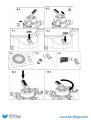
7. Connecting the appliance to the pool – see FIG. 7.1. and 7.2.
Use suitable pool hoses and hose clamps to connect the appliance to the pool.
Product operation
1. Pump Watering/venting
Remove the lid off the “ODPAD/WASTE” port (FIG. 8.1), turn the lever of the valve to the VENTING position
and wait until water starts pouring out of the port (FIG. 8.2). Afterwards, switch the valve lever to the CLOSED
position and screw the lid back on. Finally, switch the lever to the FILTERING position. You can now run the
filtering.
Prior to the first use or after a sand filling replacement, you first need to rinse the sand.
2. Start-up
Use the switch at the rear of the filtering equipment to activate the device.
ON – FIG. 9.1
OFF – FIG. 9.2
Prior to plugging the appliance into the mains, check the valve position!
Never turn the appliance on if the six-way valve is in the CLOSED position or if the circulation
pipeline is impassable.
2.A Azuro equipment with the “T” marking features an adjustable timer (FIG. 9.3):
Use the moving switch to select the required functionality. The timer can be set by 20-minute steps in a 24-
hour cycle. One step corresponds to 20 minutes, which makes 3 steps equal to 1 hour. The LED indicator indicates
the device is running.
3. Operation
Set the valve to the FILTERING position and turn the appliance on. Regularly check the filtering flow-through
(pressure on the pressure gauge) and rinse the sand based on the measured values.
It is advisable to set a filtering schedule corresponding to the size and usage of the pool. Proper filtering is
contingent upon having the water filtered at least once a day. Therefore, the minimum operation time of the
filtering equipment is the volume of the pool divided by the flow-through of the filtering equipment.
Example: When using AZURO 2m
3
/hr to filter a 10m
3
pool, the minimum time would be 5 hours.
4. Prefilter Cleaning
If the prefilter is visibly dirty or the functionality of the filtering equipment is diminished, clean the prefilter
with a stream of water (FIG. 10.1). AZURO 6m³/h + Timer (FIG. 10.2).
5. Sand Rinsing
It is possible to tell by the vessel pressure when it’s necessary to rinse the filtering medium. After the first
running with clean filtering sand, make note of the pressure value; if the pressure later rises by more than one
unit on the scale, you need to RINSE (2–3 minutes) + FLUSH (about 30 seconds) – see “Valve Positions”. If filtering
is performed every day, it is recommended to rinse the sand at least once per week.
For the filtering functions such as RINSE, FLUSH and WASTE, you can use the waste set – screw the arbour (or
an elbow with the waste hose arbour) directly onto the “ODPAD/WASTE” port instead of a cap.
WHEN DRAINING WATER FROM THE “ODPAD/WASTE” PORT, MAKE SURE YOU COMPLY WITH ALL LEGAL
REQUIREMENTS FOR WASTE WATER HANDLING. DO NOT LET THE WATER INTO PLACES WHERE IT COULD CAUSE
DAMAGE BY FLOODING. THE “ODPAD/WASTE” PORT CAN BE FITTED WITH WASTE HOSE CONNECTION
THREADING. WHEN FILTERING, THE “ODPAD/WASTE” PORT SHOULD BE CLOSED BY A CAP.

Controlling the Multi-port Valve
Always disconnect the appliance from the power supply
prior to valve position changes.
Prior to the handling, wait for about half a minute after the
pump has been turned off to let the impurities and sand set
down.
Push the lever downwards (FIG. 12.1), turn it to the required position (OBR 12.2).
Care
Visible impurities are removed using the filtering system. However, that is not the case for algae, bacteria and
micro-organisms, which are a constant obstacle when striving for clean, safe water in your pool. There are many
specialized preventive products, which in correct concentrations work against all of the above and keep the water
in your pool hygienically sound and clean.
Maintenance
During the swimming season, regularly check the operation of the appliance. It is important for identification and
remedy of potential defects. The supplier cannot be held liable for damage cause by filtering unit or electrical
equipment defects.
Rinse the sand on regular basis. If the rinsing does not improve the permeability of the filtering sand (i.e. the
pressure gauge value remains high), change the sand.
Do not use solvents to clean the filter cap or the vessel itself, as you could damage its surface (it could lose its
gloss, transparency etc.).
Winterizing
At the end of the season, it is necessary to clean, drain, disassemble and store the filtering equipment. Disconnect
the filtering equipment from the pool and use the draining valve, which is located at the bottom of the filtering
vessel, to drain the water from the vessel.
Open the filter vessel and take the sand out. Clean the sand and remove any lumps or gobs. Change the sand in
the vessel on regular basis.
As preparation for winter, re-assemble the filtering equipment and store it in a winter-resistant and dry room.
Turn the valve lever to the VENTING/WINTERIZING position, which is used to winterize the filtering equipment.
Warranty Terms and Servicing
Warranty conditions apply as described in the seller’s warranty certificate.
In case you need an advice, service support or a spare part, contact your dealer. Use original spare parts for
maintenance and repair purposes.
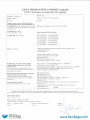
Product Tests
The product is a subject to EN 60335-2-41 and in conformity with the directives 2006/42/ES (the machinery
directive), 2014/30/EU (electromagnetic compatibility), 2014/35/EU (electrical devices) and the requirements of
the RoHS directive on hazardous substance content in electrical devices.
The product has been tested in the Government Testing
Laboratory of Machines
over the protruding thread and screw the socket on (FIG. 1.2

Troubleshooting
Low or no flow-through
The filtering equipment has not
been vented. Vent the filtering equipment.
Valve lever in the CLOSED
position Switch to the FILTERING position.
Sand is too dirty. RINSE or change the sand.
Clogged prefilter Demount and rinse the prefilter.
Clogged skimmer Demount and rinse the skimmer basket.
Damaged filtering equipment Please contact servicing.
Sand is getting to the pool.
Handling the valve lever when
filtering is underway
Turn the filtering off prior to handling the
lever.
Low granularity of the filtering
sand The recommended granularity is 0.6–1.2 mm.
High sand level in the vessel Reduce the sand level in the vessel
The pump sucks air in
(bubbles are forming in the
system)
Insufficiently tightened
connections Carefully tighten the swivel nuts.
Leaks in the prefilter
connections Re-seal the connections.
Damaged sealing
Check the connection sealing “upstream” of
the pump.
Water leaks from the
appliance
Leaking connections Tighten/re-seal the connections.
Damaged sealing Check the sealing.
Water in the pool cannot be
cleaned.
Insufficient chemical treatment
for the water
Check the pH and chlorine content in the
water.
Insufficient filtering time Extend the filtering time.


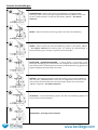
Valve Positions
RINSE – water flows through the sand in the opposite direction, washing away
impurities; instead of flowing back to the pool, it is drained through the “WASTE” port –
remove the cap!
BYPASS – water flows though the appliance, bypassing the sand filling.
WASTE – water bypasses the sand filling and flows into the “WASTE” port – remove the
cap! This position is used to reduce water level in the pool or extraction of rough
impurities.
VENTING/WINTERIZING – in this position, the valve is permeable in all directions; the
escaping air causes watering of the pump chamber. The position is also used for
winterizing or long-term filtering equipment shutdowns.
FLUSH – this position is used when running for the first time with a new sand filling or
after RINSING; the stirred sand sets down and remaining impurities are flushed through
the “WASTE” port – remove the cap!
FILTERING – primary position of the valve, the water is filtered through the sand filling
and returned to the pool.
CLOSED – do not turn the appliance on!

SANDFILTER
Azuro 2m
3
/h
Azuro 4m
3
/h + Timer
Azuro 6m
3
/h + Timer
Für Aufstellpool
Installations-, Einbau- und Bedienungsanleitung
(Originalbetriebsanleitung)
VOR INSTALLATION UND GEBRAUCH DIESES PRODUKTES BITTE ALLE IN
DIESER BETRIEBSNALEITUNG ANGEFÜHRTEN ANWEISUNGEN
DURCHLESEN, VERSTEHEN UND BEACHTEN. BEWAHREN SIE DIESE
ANLEITUNG FÜR EVENTUELLEN KÜNFTIGEN BEDARF AUF.
Version 1 / Stand März 2020

Sicherheitshinweise
In dieser Anleitung sind mit diesem Symbol Anweisungen gekennzeichnet, bei deren
Nichtbeachtung Personenschäden entstehen können.
In dieser Anleitung sind mit diesem Symbol Anweisungen gekennzeichnet, bei deren
Nichtbeachtung Stromschlaggefahr besteht.
WENN DIE ANLAGE BEDIENT WIRD ODER WENN
PERSONEN IM SCHWIMMBECKEN BADEN, IST DIE
ANLAGE VOM NETZ ZU TRENNEN
FOLGENDE HINWEISE DURCHLESEN UND BEACHTEN
Die Nichteinhaltung der in dieser Anleitung angeführten Hinweise kann eine
Verletzung oder sogar den Tod durch Stromschlag zur Folge haben!
Die Anlage können Kinder ab 8 Jahren und Personen mit eingeschränkten körperlichen, sinnlichen
oder geistigen Fähigkeiten oder mit unzureichenden Kenntnissen und Erfahrungen nur dann
benutzen, wenn sie von einer eingewiesenen erwachsenen Person beaufsichtigt werden oder wenn
sie in die sichere Verwendung der Anlage unterwiesen wurden und die etwaigen Gefahren
verstehen. Kinder dürfen mit der Anlage nicht spielen. Reinigung und Wartung dürfen nicht von
unbeaufsichtigten Kindern durchgeführt werden.
Die Anlage nur an eine Stromversorgungsleitung, die den einschlägigen ČSN-Normen entspricht, und
in eine Steckdose einstecken, die sich in einer Entfernung von min. 3,5 m von dem Schwimmbecken
befindet, und zwar über einen Stromschutzschalter mit einem Bemessungsausschaltstrom von
höchstens 30 mA.
Die Anlage direkt in die Steckdose einstecken. Beim Einsatz eines Verlängerungskabels nur ein
Kabel verwenden, das der ČSN-Norm für den Gebrauch im Freien entspricht.
Versuchen Sie nicht, den Stecker des Netzkabels in die Steckdose zu stecken oder ihn aus der
Steckdose zu ziehen, wenn Sie nasse Hände haben oder im Wasser stehen.
Positionieren Sie das Gerät so, dass es Kindern nicht als Hilfsmittel zum Betreten des Pools dienen
kann.
Kinder vom Gerät und vom Netzkabel fernhalten. Dafür sorgen, dass keine Kinder mit dem Gerät
spielen.
Das Netzkabel nicht im Boden verlegen, sonst kann dieses beschädigt werden. Es ist so zu
positionieren, dass es nicht durch Grasmäher, Heckenscheren oder Ähnliches beschädigt werden
kann.
Die Gabel der Zuleitung für die Bedienung zugänglich lassen, damit das Gerät von der
Stromversorgung sofort getrennt werden kann.
Bevor Personen ins Schwimmbad gehen, ist das Gerät vom Stromnetz zu trennen. Das Gerät darf
nicht verwendet werden, wenn sich im Schwimmbad Menschen befinden.
Das Gerät niemals ohne Wasser betreiben.
Das Gerät nie betreiben, falls dieses beschädigt oder unvollständig ist. Eventuell auftretende Mängel
sind unverzüglich zu beheben. Bei der Wartung und bei Instandsetzungen verwenden Sie Original-
Ersatzteile.

Das Gerät nie einschalten, wenn sich das 6-Wege-Ventil in der Stellung „GESCHLOSSEN“ befindet
oder wenn die Rohrleitung im Umlaufsystem verstopft ist; das 6-Wege-Ventil kann beschädigt
werden, bersten oder das Ventildeckel kann abgerissen werden, was zu Personen- oder Sachschäden
führen kann.
Die Filterverstopfung regelmäßig prüfen und den Pumpen-Vorfilter sowie Skimmerkorb reinigen, um
Beschädigungen der Anlage zu vermeiden und eine ordentliche Funktion des Systems
sicherzustellen.

Komponentenverzeichnis – AZURO 2m
3
/h
Position
Bezeichnung Menge
Position Bezeichnung Menge
1 Mehrwegeventil 1
14 Saugrohr 1
2 Stöpsel 2
15 Saugkorb 1
3 Flache Stopfen-Dichtung 2
16 Saugkorbboden 1
4 Flache Manometer-Dichtung 1
17 Behälter 1
5 Manometer 1
18 Schütte 1
6
Ventilfassung 1/2 einschl.
Verbindungsmaterial
2
19 Sockel mit Pumpe 1
7
Formdichtung
–
Dorne und
Winkelstücke
4
20 Vorfilter 1
8
Überwurfmutter
–
Dorne und
Winkelstücke
4
21 Beckenschlauch 3tlg. 2
9 Winkelstück D38 2
22 Schlauchschelle 25-40 4
10 Schlauchschelle 40-60 2
23 Ablauf-Set 1
11 Dorn D32/38 2
24 Flache Vorfilter-Dichtung 1
12 Verbindungsschlauch 1
25 Teflonband 1
13 Ablasssieb 1
26
Gitter gegen Eindringen von
Fremdkörpern
1
Seite wird geladen ...
Seite wird geladen ...
Seite wird geladen ...
Seite wird geladen ...
Seite wird geladen ...
Seite wird geladen ...
Seite wird geladen ...
Seite wird geladen ...
Seite wird geladen ...
Seite wird geladen ...
Seite wird geladen ...
Seite wird geladen ...
-
 1
1
-
 2
2
-
 3
3
-
 4
4
-
 5
5
-
 6
6
-
 7
7
-
 8
8
-
 9
9
-
 10
10
-
 11
11
-
 12
12
-
 13
13
-
 14
14
-
 15
15
-
 16
16
-
 17
17
-
 18
18
-
 19
19
-
 20
20
-
 21
21
-
 22
22
-
 23
23
-
 24
24
-
 25
25
-
 26
26
-
 27
27
-
 28
28
-
 29
29
-
 30
30
-
 31
31
-
 32
32


BSVILLAGE Azuro 6m3/h + Timer Installation, Assembly And Operation Manual
- Kategorie
- Oberirdisches Poolzubehör
- Typ
- Installation, Assembly And Operation Manual
- Dieses Handbuch eignet sich auch für
in anderen Sprachen
- English: BSVILLAGE Azuro 6m3/h + Timer
Andere Dokumente
-
Steinbach Speed Clean Classic 310 Benutzerhandbuch
-
monzana 109224 Assembly Instructions
-
Espa FKP 520 6LT Benutzerhandbuch
-
 EXIT Toys 38582978 Ground Swimming Pool Benutzerhandbuch
-
 Sunbay Azul Benutzerhandbuch
-
Bestway Flowclear 58199 Bedienungsanleitung
-
Jacuzzi PREMIUM J-230 Bedienungsanleitung
-
Metabo HWW 4000/20 S Bedienungsanleitung
-
Pentair Clean & Clear RP Cartridge Filter Benutzerhandbuch
-

