Lincoln Electric Handy MIG Benutzerhandbuch
- Kategorie
- Schweißsystem
- Typ
- Benutzerhandbuch

IM3000
06/2003
Rev. 0
HANDY MIG / HANDY CORE
OPERATOR’S MANUAL
MANUALE OPERATIVO
BEDIENUNGSANLEITUNG
MANUAL DE INSTRUCCIONES
MANUEL D'UTILISATION
BRUKSANVISNING OG DELELISTE
GEBRUIKSAANWIJZING
BRUKSANVISNING
INSTRUKCJA OBSŁUGI
BESTER S.A.
ul. Jana III Sobieskiego 19A, 58-260 Bielawa, Poland
www.lincolnelectric.com

2
Declaration of conformity
Dichiarazione di conformità
Konformitätserklärung
Declaración de conformidad
Déclaration de conformité
Samsvars erklæring
Verklaring van overeenstemming
Försäkran om överensstämmelse
Deklaracja zgodności
BESTER S.A.
Declares that the welding machine:
Dichiara che Il generatore per saldatura tipo:
Erklärt, daß die Bauart der Maschine:
Declara que el equipo de soldadura:
Déclare que le poste de soudage:
Bekrefter at denne sveisemaskin:
Verklaart dat de volgende lasmachine:
Försäkrar att svetsomriktaren:
Deklaruje, że spawalnicze źródło energii:
HANDY MIG / HANDY CORE s/n
conforms to the following directives:
è conforme alle seguenti direttive:
den folgenden Bestimmungen entspricht:
es conforme con las siguientes directivas:
Est conforme aux directives suivantes:
er i samsvar med følgende direktiver:
Overeenkomt conform de volgende richtlijnen:
överensstämmer med följande direktiv:
spełnia następujące wytyczne:
73/23/CEE, 93/68/CEE, 89/336/CEE, 92/31/CEE
and has been designed in conformance with the following norms:
ed è stato progettato in conformità alle seguenti norme:
und in Übereinstimmung mit den nachstehenden Normen hergestellt wurde:
y ha sido diseñado de acuerdo con las siguientes normas:
et qu'il a été conçu en conformité avec les normes:
og er produsert og testet iht. følgende standarder:
en is ontworpen conform de volgende normen:
och att den konstruerats i överensstämmelse med följande standarder:
i że zostało zaprojektowane zgodnie z wymaganiami następujących norm:
EN 50199, EN 60974-1
BESTER S.A., ul. Jana III Sobieskiego 19A, 58-260 Bielawa, Poland
06/02

4
Safety 02/02
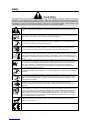
WARNING
This equipment must be used by qualified personnel. Be sure that all installation, operation, maintenance and repair
procedures are performed only by qualified individuals. Read and understand this manual before operating this
equipment. Failure to follow the instructions in this manual could cause serious personal injury, loss of life, or damage to
this equipment. Read and understand the following explanations of the warning symbols. Lincoln Electric is not
responsible for damages caused by improper installation, improper care or abnormal operation.
WARNING: This symbol indicates that instructions must be followed to avoid serious personal injury,
loss of life, or damage to this equipment. Protect yourself and others from possible serious injury or
death.
READ AND UNDERSTAND INSTRUCTIONS: Read and understand this manual before operating
this equipment. Arc welding can be hazardous. Failure to follow the instructions in this manual could
cause serious personal injury, loss of life, or damage to this equipment.
ELECTRIC SHOCK CAN KILL: Welding equipment generates high voltages. Do not touch the
electrode, work clamp, or connected work pieces when this equipment is on. Insulate yourself from
the electrode, work clamp, and connected work pieces.
FUMES AND GASES CAN BE DANGEROUS: Welding may produce fumes and gases hazardous to
health. Avoid breathing these fumes and gases. To avoid these dangers the operator must use
enough ventilation or exhaust to keep fumes and gases away from the breathing zone.
ARC RAYS CAN BURN: Use a shield with the proper filter and cover plates to protect your eyes from
sparks and the rays of the arc when welding or observing. Use suitable clothing made from durable
flame-resistant material to protect you skin and that of your helpers. Protect other nearby personnel
with suitable, non-flammable screening and warn them not to watch the arc nor expose themselves to
the arc.
WELDING SPARKS CAN CAUSE FIRE OR EXPLOSION: Remove fire hazards from the welding
area and have a fire extinguisher readily available. Welding sparks and hot materials from the welding
process can easily go through small cracks and openings to adjacent areas. Do not weld on any
tanks, drums, containers, or material until the proper steps have been taken to insure that no
flammable or toxic vapors will be present. Never operate this equipment when flammable gases,
vapors or liquid combustibles are present.
ELECTRICALLY POWERED EQUIPMENT: Turn off input power using the disconnect switch at the
fuse box before working on this equipment. Ground this equipment in accordance with local electrical
regulations.
ELECTRICALLY POWERED EQUIPMENT: Regularly inspect the input, electrode, and work clamp
cables. If any insulation damage exists replace the cable immediately. Do not place the electrode
holder directly on the welding table or any other surface in contact with the work clamp to avoid the
risk of accidental arc ignition.
ELECTRIC AND MAGNETIC FIELDS MAY BE DANGEROUS: Electric current flowing through any
conductor creates electric and magnetic fields (EMF). EMF fields may interfere with som e
pacemakers, and welders having a pacemaker should consult their physician before operating this
equipment.
CYLINDER MAY EXPLODE IF DAMAGED: Use only compressed gas cylinders containing the
correct shielding gas for the process used and properly operating regulators designed for the gas and
pressure used. Always keep cylinders in an upright position securely chained to a fixed support. Do
not move or transport gas cylinders with the protection cap removed. Do not allow the electrode,
electrode holder, work clamp or any other electrically live part to touch a gas cylinder. Gas cylinders
must be located away from areas where they may be subjected to physical damage or the welding
process including sparks and heat sources.
WELDED MATERIALS CAN BURN: Welding generates a large amount of heat. Hot surfaces and
materials in work area can cause serious burns. Use gloves and pliers when touching or moving
materials in the work area.
CE COMPLIANCE: This equipment complies to the European Communities directives.

5
SAFETY MARK: This equipment is suitable for supplying power for welding operations carried out in
an environment with increased hazard of electric shock.
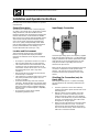
Installation and Operator Instructions
Read this entire section before installation or operation
of the machine.
General Description
The machine is a semiautomatic constant voltage DC
arc welder. The machine uses a single phase constant
voltage transformer, solid state rectifier and a DC
permanent magnet motor for feeding and welding solid
steel electrode and flux-cored electrode (for HANDY
MIG) and only flux-cored electrode (for HANDY CORE).
This machine is ideally suited for individuals having
access to 230 volt AC input power and wanting the
ease of use, quality and dependability of both metal
inert gas (MIG) welding and the Innershield electrode
process (self-shielded flux-cored welding). The
machine will handle reels of wire up to 1 Kg.
Location and Environment
This machine will operate in harsh environments.
However, it is important that simple preventative
measures are followed to assure long life and reliable
operation.
• Do not place or operate this machine on a surface
with an incline greater than 15° from horizontal.
• This machine must be located where there is free
circulation of clean air without restrictions for air
movement to and from the air vents. Do not cover
the machine with paper, cloth or rags when
switched on.
• Dirt and dust that can be drawn into the machine
should be kept to a minimum.
• This machine has a protection rating of IP21. Keep
it dry when possible and do not place it on wet
ground or in puddles.
• Locate the machine away from radio controlled
machinery. Normal operation may adversely affect
the operation of nearby radio controlled machinery,
which may result in injury or equipment damage.
Read the section on electromagnetic compatibility
in this manual.
• Do not operate in areas with an ambient
temperature greater than 40°C.
Input Supply Connection
Check the input voltage, phase, and frequency supplied
to this machine before turning it on. The allowable input
voltage is indicated in the technical specification section
of this manual and on the rating plate of the machine.
Verify the connection of grounding wires from the
machine to the input source.
Make sure the amount of power available from the input
connection is adequate for normal operation of the
machine. The necessary fuse and cable sizes are
indicated in the technical specification section of this
manual.
Shielding Gas Connection (only for
Handy MIG)
When using the MIG process, a cylinder of shielding
gas (appropriate for the metal being welded) must be
obtained.
1. Chain the cylinder to a wall or other stationary
support to prevent the cylinder from the work circuit
and earth ground.
2. With the cylinder securely installed, remove the
cylinder cup. Stand to one side away from the
outlet and open the cylinder valve very slightly for
an instant. This blows away any dust or dirty which
may have accumulated in the valve outlet. Install
the regulator on the gas cylinder.
3. Attach one end of the inlet hose to the output of the
regulator secure with hose clamp. Connect the
other end to the Gas Inlet Fitting on the machine
and secure with hose clamp. Make certain the gas
inlet hose is not kinked or twisted.

6
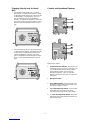
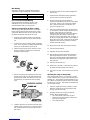
Changing Polarity (only for Handy
MIG)
1. For Negative Polarity welding (DC-): Refer to
below Figure. As delivered, the machine is wired
for Negative polarity with the gun cable connected
to the Negative (-) output terminal. This is the
typical configuration for Flux Cored Welding
(FCAW). To complete the installation, connect the
work cable’s terminal lug to the Positive (+) output
terminal. Make sure that both thumbscrews are
tigh.
2. For Positive Polarity (DC+): Refer to below Figure.
To wire for Positive polarity, connect the gun cable
to the Positive (+) output terminal and the work
cable to the Negative (-) terminal. This is the
typical configuration for the Metal Inert Gas (MIG)
process. Make sure that both thumbscrews are
tight.
Controls and Operational Features
Refer to above Figures.
1. Thermal Protection Indicator: The machine has
a rated output duty cycle of 20%. If the duty cycle
is exceeded, thermal protector will shut off the
output until the machine cools to a normal
operating temperature. This is an automatic
function of the machine and does not require user
intervention.
2. Wire Speed Control
3. Power ON/OFF Switch: When the power is ON
the welding output and wire feeder are ON (“hot”)
when the gun trigger is pressed.
4. Low / High Heat Range Switch: A rocker switch
control that gives low or high coarse range
adjustment of the power source output voltage.
5. 1 - 2 Fine Heat Adjustment Switch: Allows fine
adjustment of the voltage within the selected Low
or High output range.

7
MIG Welding
Table below shows the recommended material/gas
combinations for MIG welding with solid electrodes.
Material Gas
Carbon Steel CO2 or Argon / CO2
Low Alloy Steel CO2 or Argon / CO2
Flux-cored (Innershield) Welding
The recommended electrode for the flux-cored,
selfshield process is 0.9 mm diameter Lincoln
Innershield NR-211-MP on 0.45 kg spools.
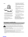
Sequence of Operations for Wire Loading
Turn machine power switch to the OFF (“0”) position
before working inside the wire feed enclosure. Make
sure that the wire feed drive roll and contact tip of the
gun match the diameter and type of wire used.
1. Push the spool onto the spindle so that the wire
feeds off the bottom of the spool, toward the drive
roll.
2. Push the spool spacer onto the spindle, against the
spool. If it is necessary, for getting proper breaking
torque you should rotate the spool spacer.
3. Slide the spring onto the spool, then press on the
spool lock, turning it clockwise to lock the spool
assembly onto the spindle.
4. Release the spring loaded thumbscrew and rotate
the idle roll arm away from the wire feed drive roll.
Ensure that the visible, stenciled size on the drive
roll side facing you matches the wire size being
used.
5. Carefully detach the end of the wire from the spool
maintain tension on the wire. To prevent the spool
from unwinding and do not release the wire until
after step 8.
6. Cut the bent portion of wire off and straighten the
first 100 mm.
7. Thread the wire through the ingoing guide tube,
over the drive roll, and into the gun liner.
8. Close the idle roll arm and turn down the
thumbscrew until the idle roller presses down firmly
on the wire. (Now you may release the welding
wire.) Make sure the wire is positioned in the
groove of lower drive roll.
9. The spring loaded thumbscrew on the idle roll arm
can be used as a “brake” to adjust the pressure on
the wire. Adjust pressure by turning the
thumbscrew to prevent wire overrun, but still allow
smooth and easy wire feeding. Start with the
pressure set to an intermediate value. Readjust, if
necessary. Slightly less pressure may be required
when using 0.6 mm wire. If the drive roll slips while
feeding wire, the pressure should be increased
until the wire feeds properly.
10. Remove the nozzle and contact tip from the gun.
11. Turn the machine ON (“I”).
12. Straighten the gun cable assembly.
13. Depress the gun trigger switch and feed welding
wire through the gun and cable. (Point the gun
away from yourself and others while feeding wire.)
Release the gun trigger after wire appears at the
end of the gun.
14. Turn the machine OFF (“0”).
15. Replace the contact tip. Cut the wire off so that 10
to 15 mm protrudes from the end of the tip.
16. Turn on the machine. The machine is now ready to
weld.
Shielding Gas (only for Handy MIG)
When using the MIG process, you will need a cylinder
of carbon dioxide (CO2) or argon-carbon dioxide mixed
shielding gas. The regulator should be installed on the
gas cylinder. An adapter and plastic washer are needed
for using 100% CO2 gas. This adapter is available from
your local gas supplier.
1. Open the cylinder valve slowly a fraction of a turn.
When the cylinder pressure gauge pointer stops
moving, open the valve fully.
2. Keep the cylinder valve closed, except when
welding. When finished welding:
• Close the cylinder valve to stop gas flow.
• Depress the gun trigger briefly to release the
pressure in the gas hose.
• Turn off the machine.

8
Welding
1. Select the right welding process based on the type
and condition of the pieces to be welded; the
environment in which welding is to be done; and
the desired finished appearance of the weld.
2. Select and install the welding wire to match the
process. Use Genuine Lincoln Electric Brand wire.
Wire quality is essential for successful welding.
3. Install the drive roll, contact tip, and nozzle
appropriate for the weld process.
4. Check that the polarity is correct for the welding
wire being used and that the gas supply, if
required, is turned on.
5. Refer to above Figure. Connect the work clamp to
the metal to be welded. The work clamp must
make good electrical contact to the work piece.
The work piece must also be grounded as stated in
Welding Safety Precautions in the beginning of this
manual.
6. Based on the welding process type and material
thickness of the work piece, set the correct wire
speed and heat range setting.
7. Based on the weld joint type and orientation of the
weld joint, position the gun into the joint at the
correct angel.
8. To begin welding, raise your hand shield to protect
your eyes and pull the trigger.
9. While welding, travel at a constant speed and
maintain an electrode stickout of 9 mm. Follow the
correct direction of travel for the process and joint
type and orientation.
10. To stop welding, release the gun trigger.
11. When no more welding is to be done, close the
valve on the gas cylinder (if used), momentarily
operate the gun trigger to release gas pressure,
and turnoff the machine.
Cleaning Tip and Gas Nozzle
Clean the contact tip and gas nuzzle to avoid arc
bridging between them. Bridging can result in a shorted
nozzle, poor welds and an overheating gun. Anti-stick
spray or gel, available from a welding distributor, may
reduce buildup and aid in spatter removal.
Electromagnetic Compatibility (EMC) 02/02
This machine has been designed in accordance with all relative directives and norms. However, it may still generate
electromagnetic disturbances that can affect other systems like telecommunications (telephone, radio, and television) or
other safety systems. These disturbances can cause safety problems in the affected systems. Read and understand
this section to eliminate or reduce the amount of electromagnetic disturbance generated by this machine.
This machine has been designed to operate in an industrial area. To operate in a domestic area it is
necessary to observe particular precautions to eliminate possible electromagnetic disturbances. The
operator must install and operate this equipment as described in this manual. If any electromagnetic
disturbances are detected the operator must put in place corrective actions to eliminate these disturbances
with, if necessary, assistance from Lincoln Electric.
Before installing the machine, the operator must check the work area for any devices that may malfunction because of
electromagnetic disturbances. Consider the following.
• Input and output cables, control cables, and telephone cables that are in or adjacent to the work area and the
machine.
• Radio and/or television transmitters and receivers. Computers or computer controlled equipment.
• Safety and control equipment for industrial processes. Equipment for calibration and measurement.
• Personal medical devices like pacemakers and hearing aids.
• Check the electromagnetic immunity for equipment operating in or near the work area. The operator must be sure
that all equipment in the area is compatible. This may require additional protection measures.
• The dimensions of the work area to consider will depend on the construction of the area and other activities that are
taking place.

9
Consider the following guidelines to reduce electromagnetic emissions from the machine.
• Connect the machine to the input supply according to this manual. If disturbances occur if may be necessary to take
additional precautions such as filtering the input supply.
• The output cables should be kept as short as possible and should be positioned together. If possible connect the
work piece to ground in order to reduce the electromagnetic emissions. The operator must check that connecting
the work piece to ground does not cause problems or unsafe operating conditions for personnel and equipment.
• Shielding of cables in the work area can reduce electromagnetic emissions. This may be necessary for special
applications.
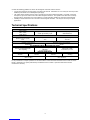
Technical Specifications
INPUT
Input Voltage
230 V ± 10%
Single Phase
Input Power at Rated Output
2.5 kW @ 20% Duty Cycle Frequency
50/60 Hertz (Hz)
RATED OUTPUT AT 40°C
Duty Cycle
(Based on a 10 min. period)
20%
Output Current
70 A
Output Voltage
17.5 Vdc
OUTPUT RANGE
Welding Current Range
45-80 Amps Maximum Open Circuit Voltage
29 Vdc
RECOMMENDED INPUT CABLE AND FUSE SIZES
Fuse or Circuit Breaker Size
16 A Superlag Type of Plug
16A/250V
(Included with Machine)
Input Power Cable
3 Conductor, 1.5 mm2
PHYSICAL DIMENSIONS
Height
345 mm Width
220 mm Length
455 mm Weight
20.9 Kg
Operating Temperature
–20°C to +40°C Storage Temperature
-25°C to +55°C
For any maintenance or repair operations it is recommended to contact the nearest technical service center or Lincoln
Electric. Maintenance or repairs performed by unauthorized service centers or personnel will null and void the
manufacturers warranty.
-
 1
1
-
 2
2
-
 3
3
-
 4
4
-
 5
5
-
 6
6
-
 7
7
-
 8
8


Lincoln Electric Handy MIG Benutzerhandbuch
- Kategorie
- Schweißsystem
- Typ
- Benutzerhandbuch
