

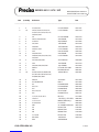
PAG OERLIKON AG
SERIES-300 S / SCS / SIP
INDEX (11.03.97)
00.01
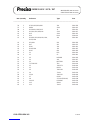
CONTENTS SECTION PAGE
INHALT REGISTER SEITE
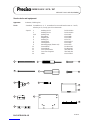
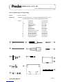
General Instructions / Accessories A
Allgemeine Hinweise / Zubehör
- Elementary Diagram / Prinzipschaltbild A 01.01-06
- Open a balance, changing of mains voltage / Oeffnen einer Waage, Spannungsumschaltung A 02.01-03
- Multifunctionbox Board / Multifunktionsbox-Print 350-7213/10 A 03.01-02
- Connecting Cable (external T-key) / Anschlusskabel 350-8313 A 04.01-02
- Data Output (20mA current loop, bi directional) / Datenausgang 350-8803 A 05.01-02
- Remote Display (mounted to the balance) / Ferndisplay 350-8830 A 06.01-02
- Data Output (IEC 625 / IEEE 488) / Datenausgang 350-8833 / 8834 A 07.01-05
- Connecting Cable (remote display freestanding / wall mounted) / Anschlusskabel 350-8836 A 08.01-02
- Data Output (4-channel multiplexer) / Datenausgang 350-8852 A 09.01-04
- Analogue Output / Analogausgang 350-8853 A 10.01-04
- Clock / Uhrenbaustein 350-8871 A 11.01-02
- Remote Display (mounted to the balance) / Ferndisplay 350-8876 A 12.01-02
- Connecting Cable (remote display freestanding / wall mounted) / Anschlusskabel 350-8877 A 13.01-02
- Data Output (20mA current loop, bi directional) / Datenausgang 350-8878 A 14.01-02
- Connecting Cable (external T-key) / Anschlusskabel 350-8879 A 15.01-02
- Data Output (IEC 625 / IEEE 488) / Datenausgang 350-8880 / 8881 A 16.01-05
- Data Output (4-channel multiplexer) / Datenausgang 350-8882 A 17.01-04
- Analogue Output / Analogausgang 350-8883 A 18.01-04
- Interface HA 300 350-8886 A 19.01-02
- Interface HA 300 350-8887 A 20.01-02
- Interface (RS232 / V24) IP65 350-8883 A 21.01-06
- Serial Interface (20mA current loop, bi directional) IP65 350-8839 A 22.01-08
- AP11 (Application pack) IP65 350-8851 A 23.01-05
- Analogue output IP65 / Analogausgang IP65 350-8858 A 24.01-08
- Clock IP65 / Uhrenbaustein IP65 350-8888 A 25.01-05

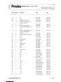
PAG OERLIKON AG
SERIES-300 S / SCS / SIP
INDEX (11.03.97)
00.02
CONTENTS SECTION PAGE
INHALT REGISTER SEITE
Mechanics / Mechanik B
- Users instructions B 01.01
- Gebrauchsanleitung B 01.02
- Balance (without weighing cell) / Waage (ohne Wägezelle) 300 S B 02.01-06
- Balance (without weighing cell) / Waage (ohne Wägezelle) 300 SIP B 02.07-09
- Balance (without weighing cell) / Waage (ohne Wägezelle) 300 SCS B 03.01-06
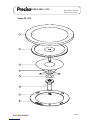
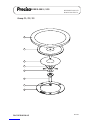
- Weighing cell / Wägezelle B 04.01-09
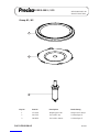
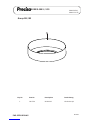
- Weighing pan D80 / Waagschale D80 B 05.01
- Weighing pan D150 / Waagschale D150 B 06.01-02
- Weighing pan D170 / Waagschale D170 B 07.01-02
- Weighing pan 223x190 / Waagschale 223x190 B 08.01
- Windshield Group A / Windschutz Gruppe A B 09.01
- Windshield Group M / Windschutz Gruppe M B 10.01
- Calibration / Kalibrierung B 11.01-02
- External power supply pack 300 SCS / Externes Netzteil 300 SCS B 12.01
- Weighing pan D 170 / 223x190 SIP / Waagschale D 170 / 223x190 SIP B 13.01-02
Electronics / Elektronik C
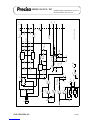
- Main board / Hauptprint 300-7218-010 C 01.01-12
- Exchange of the Main Board / Auswechseln des Hauptprintes 300-7235-010 C 02.01-13
- Analogue board / Analogprint 300-7219-010 (300 S / SIP) C 03.01-03
- Analogue board / Analogprint 300-7238-010 (300 SCS) C 04.01-03
- Power supply board / Netzteilprint 300-7215-010 (300 S) C 05.01-03
- Power supply board / Netzteilprint 300-7214-010 (300 SCS / SIP) C 06.01-03
Adjustements D
- Service tools and equipment D 01.01
- Dismantling / assembly instructions 300 S / SIP D 02.01-06
- Dismantling / assembly instructions 300 SCS D 03.01-06
- Calibration instructions D 04.01-11
- Error messages D 05.01
- Consultation with PAG Oerlikon AG D 06.01
Einstellungen E
- Service-Werkzeuge und Ausrüstung E 01.01
- Demontage- und Montageanleitung 300 S / SIP E 02.01-06
- Demontage- und Montageanleitung 300 SCS E 03.01-06
- Justieranleitung E 04.01-11
- Fehleranzeigen E 05.01
- Rücksprache mit PAG Oerlikon AG E 06.01


PAG OERLIKON AG
SERIES-300 S / SCS
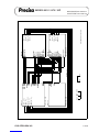
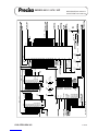
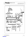
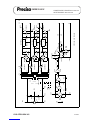
ELEMENTARY DIAGRAM / PRINZIPSCHALTBILD
A 01.02
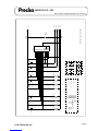
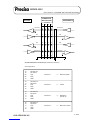
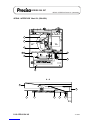
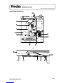
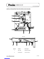
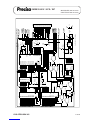
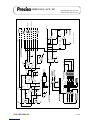
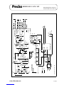
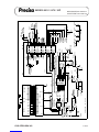
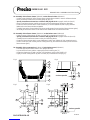
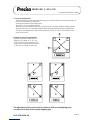
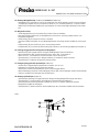
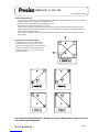
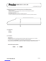
Legend of elementary diagram
1. Weighing pan
2. Support
3. Top flexure arm
4. Bottom flexure arm
5. Flexure strap
6. Balance arm
7. Vane
8. Light detector
9. Permanent magnet
10. Pole piece
11. Temperature compensation (NTC-Resistor)
12. Magnetism screen
13. Compensation coil
14. Chassis
15. Balance arm’s flexure
16. Input amplifier
17. PID-Regulator
18. Power amplifier
19. Measure resistor
20. Analogue-Digital Converter (ADC)
21. ADC-Logic
22. Buffer amplifier
23. Reference voltage source
24. Counter
25. Analogue dispaly
26. Temperature measuring circuitry
27. Microprocessor
28. Programme memory (EPROM)
29. Data memory (RAM)
30. Non-Volatile data memory (EEPROM)
31. Display controller
32. Display
33. Key driver
34. ON/OFF, MODE and T-Key
35. “Power-ON-Reset” Logic
36. Power Supply
37. Multifunctionbox
38. Analogue output
Legende zu Prinzipschaltbild
1. Waagschale
2. Gehänge
3. Lenker oben
4. Lenker unten
5. Koppel
6. Waagbalken
7. Fahne
8. Lichtschranke
9. Magnet
10. Pol
11. Temperaturfühler (NTC-Widerstand)
12. Magnet-Abschirmung
13. Spule
14. Chassis
15. Lager für Waagbalken
16. Eingangsverstärker
17. PID-Regler
18. Endverstärker
19. Messwiderstand
20. Analog-Digital-Wandler
21. Steuerlogik für AD-Wandler
22. Verstärker
23. Referenzspannungsquelle
24. Zähler
25. Analoganzeige
26. Temperaturmesschaltung
27. Microprozessor
28. Programmspeicher (EPROM)
29. Datenspeicher (RAM)
30. Nichtflüchtiger Datenspeicher (EEPROM)
31. Anzeigeansteuerung
32. Digitalanzeige
33. Tastenansteuerung
34. ON/OFF, MODE und T-Taste
35. “Power-ON-Reset” Logik
36. Netzteil
37. Multifunktionenbox (Option)
38. Datenausgänge (Option)

PAG OERLIKON AG
SERIES-300 S / SCS
ELEMENTARY DIAGRAM / PRINZIPSCHALTBILD
FUNCTIONAL DESCRIPTIOIN
Weighing System Description
Mechanics
The force caused by any weight which is placed on the weighing pan [1] reaches the support [2] directly. The
support [2] is sustained in a parallel configuration by the top [3] and bottom [4] flexure arms. The support [2]
leads the force through the flexure strap [5] to the balance arm [6] . The arm [6] is connected to the flexures
[15] on the chassis [14] . The balance arm [6] leads the force with a certain reduction ratio to the compensa-
tion coil [13] which is located in the center of the magnetic-system.
Magnetic-System
The magnetic system consists of a permanent magnet [9] and the pole piece [10] . They lead the magnetic
field to the compensation coil [13] . The magnetic system, is covered by a screen [12] , to inhibit the break-out
of the stray-field.
Balance arm location
The position of the balance arm [6] is set by the light detector [8] which gets the light through the vane [7].
Measure principle and regulation
Any weight placed on the weighing pan [1] moves the balance arm [6] from its zero-position. The light
detector [8] gives the deviation from the zero-position as an electric signal to the input amplifier [16] and to
the PID-Regulator [17] . The PID-ReguIator [17] changes its output voltage, which goes via the power
amplifier [18] to the compensation coil [13] , till the force change on the coil [13] is sufficient to put the
balance arm [6] back to its initial zero-position. The position of the balance arm [6] , is in the steady-state
now, and the current through the coil [13] is proportional to the weight placed on the weighing pan [1] .
Electronical Evaluation of the Measure Current
The coils’ current is converted to a measure voltage by the measure resistor [19] . This measure voltage
goes on the one side via the buffer-amplifier [22] , to the analogue display [25] , and the analogue output [38]
; on the other side it feeds the analogue to digital converter [20] (AD-Converter) . The AD-Converter [20]
compares the signal with the reference voltage source [23] . The AD-Converter [20] works in the “Dual-Slope-
Method” and is controlled by the microprocessor [27] by means of the AD-Logic [21] . The digital output signal
reaches the microprocessor [27] through the counter [24]. The Reset-Logic [35] supervises the power supply
[36] and enables the microprocessor [27] to run, if there is sufficient supply voltage. The microprocessor [27]
sends the display-data to the display-controller [31] , where the data is latched and displayed by the dispIay
[32] .
The keys “ON/OFF”, "MODE" and “T” [34] give information through the driver [33] to the microprocessor . If
the balance is switched off by the “ON/OFF”-key, it remains in the “standby” mode, that means the balance is
ready to work with no warm-up time after switching on again.
A 01.03

PAG OERLIKON AG
SERIES-300 S / SCS
ELEMENTARY DIAGRAM / PRINZIPSCHALTBILD
Microprocessor System
The microprocessor system consists of the following parts:
Programme [28] : Command memory of the microprocessor [27] . It contains the program-
me instructions in a “Read Only Memory” (ROM).
Data memory [29] : Data memory of the microprocessor . This memory is used to store and
read the data. After a mains failure the data is not available anymore. It is
a “Static Random Access Memory” (RAM).
Non-Volatile data memory [30] : This memory is used to store the important data that has to be available
after a mains failure (e.g. Linearity data, calibration data, temperature
adjustment data). It contains an “Electronically Erasable Programmable
Read Only Memory” (EEPROM).
The following tasks are done by the Microprocessor :
- Read and evaluated the data of the A-D Converter
- Optimize the integration time stability detection
- Measure the temperature of the weighing system
- Compensation of the temperature drift on the zero point
- Compensation of the temperature drift on the sensitivity
- Correction of non-linearity
- Calibration to a reference weight
- Drive the data-output
- Execute the multifunctionbox commands (e.g. piece-counting)
- Read the “T”, "MODE" and “ON/OFF”-keys
A 01.04

PAG OERLIKON AG
SERIES-300 S / SCS
ELEMENTARY DIAGRAM / PRINZIPSCHALTBILD
A 01.05
FUNKTIONSBESCHREIBUNG
Beschreibung der Wägezelle
Mechanik
Durch Auflegen eines Gewichtes auf die Waagschale [1] gelangt die zu messende Kraft auf das Gehänge [2].
Dieses Gehänge [2] wird durch die oberen Lenker [3] und die unteren Lenker [4] geführt. Die Kraft wird nun
über eine Koppel [5] auf den Waagbalken [6] geleitet Der Waagbalken [6] ist am Lager [15] am Chassis [14]
aufgehängt. Mit entsprechender Untersetzung leitet der Waagbalken [6] die Kraft auf die Spule [13] , die sich
im Magnetsystem befindet.
Magnetsystem
Das Magnetsystem besteht aus dem Magneten [9] und den beiden Polen [10] , die das Magnetfeld zur Spule
leiten. Um das Austreten des Streufeldes nach oben zu verhindern, ist das Magnetsystem durch die Abschir-
mung [12] abgedeckt.
Abtastung des Waagbalkens
Die Position des Waagbalkens [6] wird mit der Fahne [7] der Lichtschranke [8] zugeführt und dort optisch
abgetastet.
Messprinzip und Regelkreis
Wird ein Gewicht auf die Waagschale [1] gelegt, so bewegt sich der Waagbalken [6] aus seiner Null-Lage.
Die Lichtschranke [8] gibt nun diese Abweichung von der Null-Lage als elektrisches Signal an den Eingangs-
verstärker [16] und weiter zum PID-Regler [17] . Dieser PID-Regler [17] ändert nun seine Ausgangsspan-
nung, die über den Endverstärker [18] die Spule [13] speist, bis die Kraftänderung auf die Spule [13] aus-
reicht, um den Waagbalken [6] in seine Null-Lage zurückzudrücken. Somit ist die Lage des Waagbalkens [6]
in eingeschwungenem Zustand immer gleich und der Strom durch die Spule [13] ist proportional dem aufge-
legten Gewicht auf der Waagschale [1] .
Elektronische Auswertung des Messtroms
Mit dem Messwiderstand [19] wird der Spulenstrom in die Messpannung umgewandelt. Die Messpannung
gelangt nun einerseits über den Entkopplungsverstärker [22] zur Analoganzeige [25] und zum Analogaus-
gang [38] , andererseits wird das Signal dem Analog-Digital- Wandler [20] zugeführt. Im Analog-Digital-
Wandler [20] wird das Signal mit der Referenzspannungsquelle [23] verglichen. Der AD-Wandler arbeitet
nach dem “Dual-Slope-Verfahren”. Der AD-Wandler wird mit Hilfe der Ansteuerlogik [21] vom Microprozessor
[27] angesteuert. Der digitale Ausgang gelangt von der Steuerlogik [21] über den Zähler [24] zum Micropro-
zessor [27] . Die Reset-Logik [35] über wacht die Spannung des Netzteiles [36] und gibt den Microprozessor
[27] bei genügender Speisespannung zum Arbeiten frei. Die anzuzeigenden Daten gelangen vom Micropro-
zessor [27] zur Anzeigeansteuereinheit [31] , wo sie gespeichert und über das Display [32] angezeigt werden.
Die Tasten [34] “T”, "MODE" und “ON/OFF” geben die Information über den Treiber [33] an den
Microprozessor [27] . Wird die Waage über die Taste “ON/OFF” ausgeschaltet, so bleibt sie im “Stand by”
Betrieb, d.h. die Waage kann jederzeit wieder betriebswarm eingeschaltet werden.


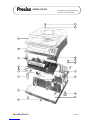
PAG OERLIKON AG
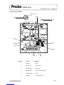
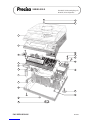
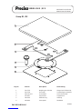
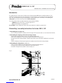
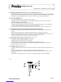
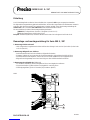
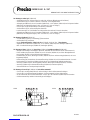
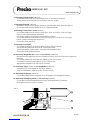
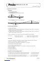
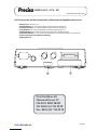
General procedure for opening a balance
1. Disconnect the balance from the mains (pull out the mains plug)
2. Remove the weighing pan and the pan holder
3. Remove the retention ring and if mounted the cover panel
4. Remove the windshield if mounted
5. Remove the dust cover
6. Loose the screw on the balance top with a screwdriver no.4
7. Lift the balance top
8. Disconnect the flat wire (3)
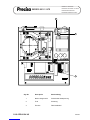
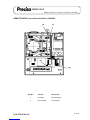
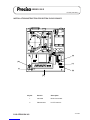
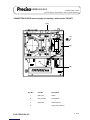
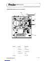
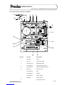
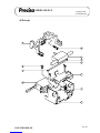
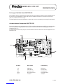
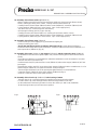
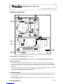
Procedure for changing the mains voltage (300S)
1.-8. See "General instructions to open a balance"
9. Turn the switch (1) into the desited position with a screwdriver no.3
10. Change or check the fuse (2)
fuse type for 110V ---> T 160 mA
fuse type for 220V ---> T 80 mA
11. Connect the flat wire (3) , reassemble the balance
Allgemeine Vorgehensweise beim Oeffnen einer Waage
1. Waage vom Netz trennen (Netzstecker ziehen)
2. Waagschale und Schalenträger entfernen
3. Haltering und evtl. Deckblech entfernen
4. evtl. Windschutz entfernen
5. Staubschutz entfernen
6. Zylinderschraube am Waagenoberteil mit einem Schraubenzieher Nr.4 lösen
7. Waagenoberteil abheben
8. Flachbandkabel (3) lösen
Vorgehensweise bei einer Spannungsumschaltung (300S)
1.-8. Siehe "Allgemeine Vorgehensweise beim Oeffnen einer Waage"
9. Drehschalter (1) mit Schraubenzieher Nr.3 auf die gewünschte Netzspannung drehen
10. Sicherung (2) auswechseln bzw. kontrollieren:
Sicherungstyp für 110V ----> T 160 mA
Sicherungstyp für 220V ----> T 80 mA
11. Flachbandkabel (3) anschliessen, Waage wieder zusammensetzen
SERIES-300 S / SCS
A 02.02
OPENING A BALANCE /
CHANGING OF MAINS VOLTAGE
ÖFFNEN EINER WAAGE /
SPANNUNGSUMSCHALTUNG

PAG OERLIKON AG
SERIES-300 SIP OPENING A BALANCE
ÖFFNEN EINER WAAGE
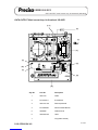
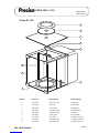
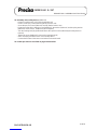
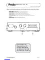
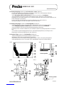
General procedure for opening a balance IP65
1. Disconnect the balance from the mains (pull out the mains plug)
2. Remove the weighing pan, lift carefully the pan holder
3. Dismantle the retention ring, take off the cover plate
4. Loose the 4 screws of the cover, take off the cover
5. Spread the locking ring and remove it
6. Take off the membrane
7. Dismantle the dust-cover, loose the screw of the housing's top
8. Lift the housing's top a bit, disconnect the flat-wire
9. Take off the housing's top
Mounting the housing's top IP65
1. Connect the flat-wire to the housing's top
2. Mount carefully the housing's top on the balance, fasten the screw on the housing's top
3. Pull the dust-cover over the balance
4. Insert the membrane, mount the locking ring
5. Align the membrane (without any stress and waves)
6. Place carefully the cover (do not move it sidewards), fasten it with 4 screws
7. Mount the cover plate and the retention ring
8. Bring carefully the pan holder in place, mount the weighing pan
Allgemeine Vorgehensweise beim Oeffnen einer Waage IP65
1. Waage vom Netz trennen (Netzstecker ziehen)
2. Waagschale abnehmen, Waagschalenträger vorsichtig herausziehen
3. Haltering demontieren, Deckblech abnehmen
4. 4 Befestigungsschrauben der Abdeckung lösen, Abdeckung entfernen
5. Klemmring leicht spreizen und abheben
6. Membrane entfernen
7. Schutzhaube abheben, Sechskantschraube am Gehäuseoberteil lösen
8. Gehäuseoberteil leicht anheben, Flachbandkabel lösen
9. Gehäuseoberteil ganz entfernen
Montage Gehäuseoberteil IP65
1. Flachbandkabel am Gehäuseoberteil anschliessen
2. Gehäuseoberteil sauber auf der Waage positionieren, Sechskantschraube anziehen
3. Staubschutzhülle über die Waage legen
4. Membrane einlegen, Klemmring montieren
5. Membrane ausrichten (spannungsfrei, ohne Wellen)
6. Abdeckung vorsichtig aufsetzen (seitlich nicht verschieben), 4 Befestigungsschrauben anziehen
7. Deckblech montieren, Haltering montieren
8. Waagschalenträger vorsichtig einfahren, Waagschale aufsetzen
A 02.03


PAG OERLIKON AG
SERIES-300 S / SCS
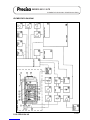
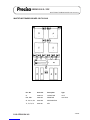
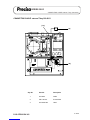
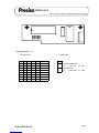
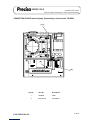
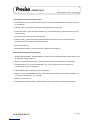
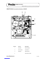
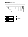
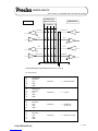
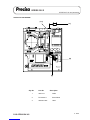
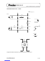
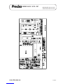
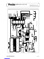
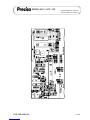
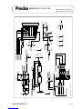
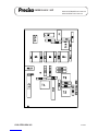
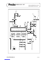
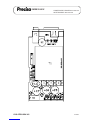
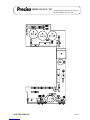
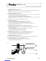
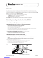
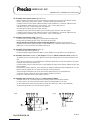
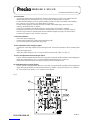
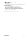
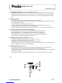
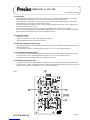
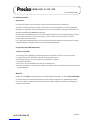
MULTIFUNCTIONBOX BOARD 350-7213-010
A 03.02
1
5
RN2D 1
2
RN1A
10k 1
3
RN1B 1
4
RN1C 1
5
RN1D 1
6
RN1E 1
7
RN1F 1
8
RN1G 1
2
RN2A 1
3
RN2B 1
4
RN2C
VCC +5V P1
SER
1
A
2
B
3
C
4
D
5
E
10
F
11
G
12
H
14
CLK
7
INH
6
SH/LD
15
CLR
9
QH 13
IC1
74HC166
C1
10uF
P2
P3
P4
CLK
PE
DATA
S4
S
S1
S
S2
S
S3
S
T3
T
T4
T
T1
T
T2
T
PRINT DIN STECKER 8-POL
GND
GND P5
T2
T4
T1
T3613
45
78
2PIN 1
PIN 2
PIN 3
PIN 4
PIN 5
PIN 6
PIN 7NC
<->
<->
<->
<->
<->
CODIERUNG
P2
P1
P5
P3
P4
PIN 8NC S3 S1 S2 S4
3507213.SCH 061288


PAG OERLIKON AG
SERIES-300 S
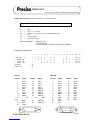
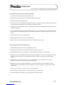
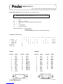
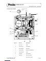
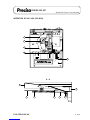
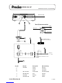
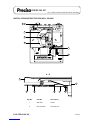
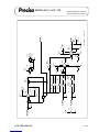
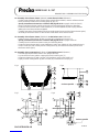
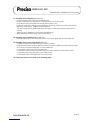
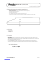
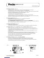
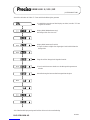
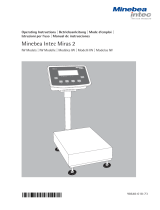
CONNECTING CABLE external T-key (350-8313)
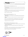
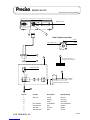
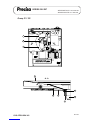
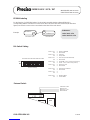
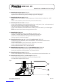
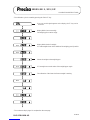
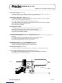
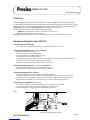
Installation instruction for connecting cable (external T-key)
1. Lift the balance top, disconnect the flat wire [A] and remove the coverplate from the data output
opening in the rear of the balance.
2. Lead the cable [1] through the opening and fix the analogue output plug with two screws [2].
3. Lead the cable [1] through the cable channel between the transformer and the partition wall and plug it to
the pin-type socket.
4. Reassemble balance, connect the flat wire [A] and mount the label [3].
-> Part-No. for external T-key: 350-8904
Einbauanleitung für Verbindungskabel (externe T-Taste)
1. Waagenoberteil abheben, Flachbandkabel [A] lösen und Datenausgang-Abdeckung auf der Rückseite
der Waage entfernen.
2. Kabel [1] durch die Öffnung führen und Stecker mit zwei Schrauben [2] festschrauben.
3. Kabel [1] durch den Kabelkanal zwischen Trafo und Gehäuse-Trennwand durchführen und auf Stiftleiste
stecken.
4. Waage wieder zusammensetzen, Flachbandkabel [A] anschliessen und Schild [3] montieren.
-> Bestellnummer für externe T-Taste: 350-8904
Notice d’installation pour Ie câble de jonction (touche-T externe)
1. Soulever la partie supérieure de la balance, débrancher le câble plat [A] et retirer le couvercle de la sortie
de données en arrière de la balance.
2. Passer le câble [1] à travers de l’ouverture et fixer Ia fiche avec deux vis [2].
3. Passer le câble [1] à travers du caniveau électrique entre le transformateur et la cloison de séparation du
boîtier et le relier avec le culot à ergots.
4. Remonter la balance, connecter de nouveau le câble plat [A] et monter l'étiquette [3].
-> Numéro de commande pour la touche T externe: 350-8904
Tare
4
6
22
6
4 Code
A 04.02

PAG OERLIKON AG
SERIES-300 S
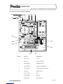
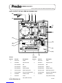
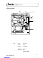
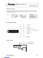
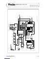
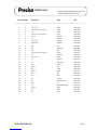
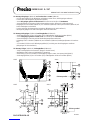
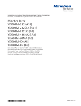
DATA OUTPUT 20mA current loop (350-8803)
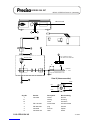
DATA OUTPUT 20mA current loop, bi-directional 350-8803
CL [5]
[1,2]
[C]
[D]
[A]
[4]
[B]
[3]
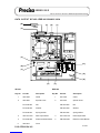
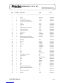
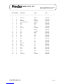
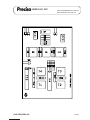
Key No. Part No. Description
1 350-7027 Cable
2 PN 1100-011 Screw M3x6
3 350-7211-010 Data output board
4 PN 1048-009 Distance holder M3x20
5 350-4033-001 Label
A 05.01

PAG OERLIKON AG
SERIES-300 S
DATA OUTPUT 20mA current loop (350-8803)
Istallation instruction for data output (20mA current loop)
1. Lift the balance top, disconnect the flat wire [D] and remove the coverplate from the data output opening in
the rear of the balance.
2. Lead the cable [1] through the opening and fix the data output plug with two screws [2]. Lead the cable [1]
through the cable channel between the transformer and the partion wall and plug it to the data output board
[3].
3. Fix the data output board [3] with two distance holders [4] on the main board [A] (with two screws [B]
from the main board). Connect the data output cable [C] on the main board [A].
4. Reassemble balance, connect the flat wire [D] and mount the label [5].
For further informations about type of data transmission and remote control commands see chapter 11.
Einbauanleitung für Datenausgang (20mA current loop)
1. Waagenoberteil abheben, Flachbandkabel [D] lösen und Datenausgang-Abdeckung auf Rückseite der
Waage entfernen.
2. Kabel [1] durch Öffnung führen und Stecker mit zwei Schrauben [2] festschrauben. Kabel [1] durch
den Kabelkanal zwischen Trafo und Gehäuse-Trennwand durchführen und mit Datenausgangsprint [3]
verbinden.
3. Datenausgangsprint [3] mit zwei Distanzhaltern [4] auf dem Hauptprint [A] befestigen (mit Schrauben
[B] vom Hauptprint). Datenausgangs-Kabel [C] mit Hauptprint [A] verbinden.
4. Waage wieder zusammensetzen, Flachbandkabel [D] anschliessen und Schild [5] montieren.
Für weitere Informationen über Art der Datenübertragung und über Fernsteuerbefehle siehe Kapitel 11.
Notice d’installation pour la sortie de données (boucle de courant 20mA)
1. Soulever la partie supérieure de la balance, débrancher le câble plat [D] et retirer le couvercle de la sortie
de données en arrière de la balance.
2. Passer le câble [1] à travers de l’ouverture et fixer la fiche avec deux vis [2]. Passer le câble [1] à
travers du caniveau électrique entre le transformateur et la cloison de séparation du boîtier et le relier avec
la carte de la sortie de données [3].
3. Fixer la carte de la sortie de données [3] avec deux ports de distance [4] sur la carte principale [A]
(avec deux vis [B] de la carte principale). Relier le câble [C] de la sortie de données avec la carte
principale [A].
4. Remonter à nouveau la balance, connecter le câble plat [D] et monter l'étiquette [5].
Plus d'informations du type de transfert de donées et des ordres de commande à distance voire chapitre 11.
A 05.02


PAG OERLIKON AG
SERIES-300 S
REMOTE DISPLAY mounted to the balance (350-8830)
Installation instruction for remote dispIay (mounted to the balance)
1. Lift the balance top, disconnect the flat wire [A] and remove the coverplate (small) from the data output
opening in the rear of the balance.
2. Lead the cable [1] through the opening and fix the display support with two screws [2]. Lead the cable [1]
through the cable channel between the transformer and the partition wall and connect it to the plug [B] on
top of the display tube.
3. Reassemble balance and connect the flat wire [A].
Einbauanleitung für Fernanzeige (am Gerät montiert)
1. Waagenoberteil abheben, Flachbandkabel [A] lösen und Datenausgang-Abdeckung (klein) auf der Rück-
seite der Waage entfernen.
2. Kabel [1] durch Öffnung führen und Fernanzeige-Stütze mit zwei Schrauben [2] festschrauben. Kabel
[1] durch den Kabelkanal zwischen Trafo und Gehäuse-Trennwand durchführen und oberhalb der Anzeige-
röhre an Stecker [B] anschliessen.
3. Waage wieder zusammensetzen und Flachbandkabel [A] anschliessen.
Notice d’instaIIation pour I’affichage à distance (fixé à la balance)
1. Soulever la partie supérieure de la balance, débrancher le câble plat [A] et retirer le couvercle de la sortie
de données (petit) en arrière de la balance.
2. Passer le câble [1] à travers de l’ouverture et fixer le support avec deux vis [2]. Passer le câble [1] à
travers du caniveau électrique entre le transformateur et la paroi de séparation du boîtier et le brancher à la
fiche [B].
3. Remonter la balance et connecter de nouveau le câble plat [A].
A 06.02

PAG OERLIKON AG
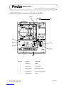
SERIES-300 S
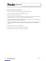
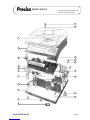
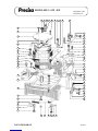
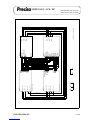
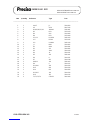
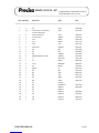
DATA OUTPUT IEC 625 / IEEE 488 (350-8833 / 8834)
A 07.01
IEC 625
Key No. Part No. Description
1 350-7028 Cable
2 350-3004 Special screw
PN 1300-003 Nut
PN 1500-030 Washer
PN 1500-034 Spring washer
3 350-7210-010 Data output board
4 PN 1048-009 Distance holder M3x20
5 350-4015 Cover
DATA OUTPUT IEC 625 / IEEE 488 350-8833 / 8834
[C] [F]
[G]
[2]
[3]
[B]
[4]
[D]
[E]
[5] [A] [1]
IEEE 488
Key No. Part No. Description
1 350-7023 Cable
2 350-3015 Special screw
PN 1300-003 Nut
PN 1500-030 Washer
PN 1500-034 Spring washer
3 350-7210-010 Data output board
4 PM 1048-009 Distance holder M3x20
[H]
1
Seite laden ...
Seite laden ...
Seite laden ...
Seite laden ...
Seite laden ...
Seite laden ...
Seite laden ...
Seite laden ...
Seite laden ...
Seite laden ...
Seite laden ...
Seite laden ...
Seite laden ...
Seite laden ...
Seite laden ...
Seite laden ...
Seite laden ...
Seite laden ...
Seite laden ...
Seite laden ...
Seite laden ...
Seite laden ...
Seite laden ...
Seite laden ...
Seite laden ...
Seite laden ...
Seite laden ...
Seite laden ...
Seite laden ...
Seite laden ...
Seite laden ...
Seite laden ...
Seite laden ...
Seite laden ...
Seite laden ...
Seite laden ...
Seite laden ...
Seite laden ...
Seite laden ...
Seite laden ...
Seite laden ...
Seite laden ...
Seite laden ...
Seite laden ...
Seite laden ...
Seite laden ...
Seite laden ...
Seite laden ...
Seite laden ...
Seite laden ...
Seite laden ...
Seite laden ...
Seite laden ...
Seite laden ...
Seite laden ...
Seite laden ...
Seite laden ...
Seite laden ...
Seite laden ...
Seite laden ...
Seite laden ...
Seite laden ...
Seite laden ...
Seite laden ...
Seite laden ...
Seite laden ...
Seite laden ...
Seite laden ...
Seite laden ...
Seite laden ...
Seite laden ...
Seite laden ...
Seite laden ...
Seite laden ...
Seite laden ...
Seite laden ...
Seite laden ...
Seite laden ...
Seite laden ...
Seite laden ...
Seite laden ...
Seite laden ...
Seite laden ...
Seite laden ...
Seite laden ...
Seite laden ...
Seite laden ...
Seite laden ...
Seite laden ...
Seite laden ...
Seite laden ...
Seite laden ...
Seite laden ...
Seite laden ...
Seite laden ...
Seite laden ...
Seite laden ...
Seite laden ...
Seite laden ...
Seite laden ...
Seite laden ...
Seite laden ...
Seite laden ...
Seite laden ...
Seite laden ...
Seite laden ...
Seite laden ...
Seite laden ...
Seite laden ...
Seite laden ...
Seite laden ...
Seite laden ...
Seite laden ...
Seite laden ...
Seite laden ...
Seite laden ...
Seite laden ...
Seite laden ...
Seite laden ...
Seite laden ...
Seite laden ...
Seite laden ...
Seite laden ...
Seite laden ...
Seite laden ...
Seite laden ...
Seite laden ...
Seite laden ...
Seite laden ...
Seite laden ...
Seite laden ...
Seite laden ...
Seite laden ...
Seite laden ...
Seite laden ...
Seite laden ...
Seite laden ...
Seite laden ...
Seite laden ...
Seite laden ...
Seite laden ...
Seite laden ...
Seite laden ...
Seite laden ...
Seite laden ...
Seite laden ...
Seite laden ...
Seite laden ...
Seite laden ...
Seite laden ...
Seite laden ...
Seite laden ...
Seite laden ...
Seite laden ...
Seite laden ...
Seite laden ...
Seite laden ...
Seite laden ...
Seite laden ...
Seite laden ...
Seite laden ...
Seite laden ...
Seite laden ...
Seite laden ...
Seite laden ...
Seite laden ...
Seite laden ...
Seite laden ...
Seite laden ...
Seite laden ...
Seite laden ...
Seite laden ...
Seite laden ...
Seite laden ...
Seite laden ...
Seite laden ...
Seite laden ...
Seite laden ...
Seite laden ...
Seite laden ...
Seite laden ...
Seite laden ...
Seite laden ...
Seite laden ...
Seite laden ...
Seite laden ...
Seite laden ...
Seite laden ...
Seite laden ...
Seite laden ...
Seite laden ...
Seite laden ...
Seite laden ...
Seite laden ...
Seite laden ...
Seite laden ...
Seite laden ...
Seite laden ...
Seite laden ...
Seite laden ...
Seite laden ...
Seite laden ...
-
 1
1
-
 2
2
-
 3
3
-
 4
4
-
 5
5
-
 6
6
-
 7
7
-
 8
8
-
 9
9
-
 10
10
-
 11
11
-
 12
12
-
 13
13
-
 14
14
-
 15
15
-
 16
16
-
 17
17
-
 18
18
-
 19
19
-
 20
20
-
 21
21
-
 22
22
-
 23
23
-
 24
24
-
 25
25
-
 26
26
-
 27
27
-
 28
28
-
 29
29
-
 30
30
-
 31
31
-
 32
32
-
 33
33
-
 34
34
-
 35
35
-
 36
36
-
 37
37
-
 38
38
-
 39
39
-
 40
40
-
 41
41
-
 42
42
-
 43
43
-
 44
44
-
 45
45
-
 46
46
-
 47
47
-
 48
48
-
 49
49
-
 50
50
-
 51
51
-
 52
52
-
 53
53
-
 54
54
-
 55
55
-
 56
56
-
 57
57
-
 58
58
-
 59
59
-
 60
60
-
 61
61
-
 62
62
-
 63
63
-
 64
64
-
 65
65
-
 66
66
-
 67
67
-
 68
68
-
 69
69
-
 70
70
-
 71
71
-
 72
72
-
 73
73
-
 74
74
-
 75
75
-
 76
76
-
 77
77
-
 78
78
-
 79
79
-
 80
80
-
 81
81
-
 82
82
-
 83
83
-
 84
84
-
 85
85
-
 86
86
-
 87
87
-
 88
88
-
 89
89
-
 90
90
-
 91
91
-
 92
92
-
 93
93
-
 94
94
-
 95
95
-
 96
96
-
 97
97
-
 98
98
-
 99
99
-
 100
100
-
 101
101
-
 102
102
-
 103
103
-
 104
104
-
 105
105
-
 106
106
-
 107
107
-
 108
108
-
 109
109
-
 110
110
-
 111
111
-
 112
112
-
 113
113
-
 114
114
-
 115
115
-
 116
116
-
 117
117
-
 118
118
-
 119
119
-
 120
120
-
 121
121
-
 122
122
-
 123
123
-
 124
124
-
 125
125
-
 126
126
-
 127
127
-
 128
128
-
 129
129
-
 130
130
-
 131
131
-
 132
132
-
 133
133
-
 134
134
-
 135
135
-
 136
136
-
 137
137
-
 138
138
-
 139
139
-
 140
140
-
 141
141
-
 142
142
-
 143
143
-
 144
144
-
 145
145
-
 146
146
-
 147
147
-
 148
148
-
 149
149
-
 150
150
-
 151
151
-
 152
152
-
 153
153
-
 154
154
-
 155
155
-
 156
156
-
 157
157
-
 158
158
-
 159
159
-
 160
160
-
 161
161
-
 162
162
-
 163
163
-
 164
164
-
 165
165
-
 166
166
-
 167
167
-
 168
168
-
 169
169
-
 170
170
-
 171
171
-
 172
172
-
 173
173
-
 174
174
-
 175
175
-
 176
176
-
 177
177
-
 178
178
-
 179
179
-
 180
180
-
 181
181
-
 182
182
-
 183
183
-
 184
184
-
 185
185
-
 186
186
-
 187
187
-
 188
188
-
 189
189
-
 190
190
-
 191
191
-
 192
192
-
 193
193
-
 194
194
-
 195
195
-
 196
196
-
 197
197
-
 198
198
-
 199
199
-
 200
200
-
 201
201
-
 202
202
-
 203
203
-
 204
204
-
 205
205
-
 206
206
-
 207
207
-
 208
208
-
 209
209
-
 210
210
-
 211
211
-
 212
212
-
 213
213
-
 214
214
-
 215
215
-
 216
216
-
 217
217
-
 218
218
-
 219
219
-
 220
220
-
 221
221
-
 222
222


Precisa 300 SIP series Benutzerhandbuch
- Typ
- Benutzerhandbuch
- Dieses Handbuch ist auch geeignet für
in anderen Sprachen
- English: Precisa 300 SIP series User manual
Sonstige Unterlagen
-
Mettler Toledo PE360 DeltaRange Bedienungsanleitung
-
-
-
 Minebea Intec Miras 2 IW Models Bedienungsanleitung
-
Mettler Toledo for Option 013 bidirectional data Bedienungsanleitung
-
 Minebea Intec YDO01M-232 (A11), YDO01M-232CLK (A31), YDO01M-232CO (A1), YDO01M-485 (A2 | A3), YDA01M-20MA (A9), YDO01M-IO (A5), YDO01M-EN (B9) Data Output Port for Midrics® COM1 and UniCOM Interfaces Bedienungsanleitung
-
 Minebea Intec Combics CAIXS2 Auswertegerät für den Einsatz in explosionsgefährdeten Bereichen Bedienungsanleitung
-
Adam Equipment GBK-M Serie Benutzerhandbuch
-
 Denver Instrument Tl-series Bedienungsanleitung
-


