MyBinding SEAL 54EL 1 Benutzerhandbuch
- Kategorie
- Laminatoren
- Typ
- Benutzerhandbuch


1
English
Introduction
We would like to thank you for purchasing a SEAL® 54/65 EL, designed to give you many years of
reliable service. By following the guidelines outlined in this manual for proper care and use, you can
depend on many years of trouble-free profitability from your investment.
Your 54/65 EL laminator meets the CE Directives (2004/108/EC, and 2006/95/EEC) and is RoHS
compliant. The laminator is also ETL listed for USA (UL 60950-1) and Canada (CSA C22.2 60950-1).
Statement of intended use.
The 54/65 EL laminator has been designed to be used with Seal® materials. When used with these
products, you are able to mount and laminate. Your machine has not been tested with any other
materials and is not recommend for use with products other than SEAL® supplies.
WARNING:
THIS MACHINE IS DESIGNED FOR MOUNTING AND LAMINATING. ANY USE
OTHER THAN THE INTENDED MAY CAUSE DAMAGE TO THE MACHINE OR
PHYSICAL HARM TO THE USER.
Liability Statement
The details given in this manual are based on the most recent information available to us. They may
be subject to change in the future. We retain the right to make changes to the construction or the
design of our products without accepting any responsibility for modifying earlier versions previously
delivered.
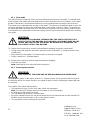
Standardized Symbols
Passages marked this way offer an idea / tip or other information on the efficient use of
this unit.
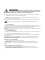
WARNING:
PLEASE PAY ATTENTION TO ALL PASSAGES MARKED THIS WAY. THIS
INFORMATION IS VITAL TO PREVENTING USER INJURY AND / OR DAMAGE TO
THE UNIT. FAILURE TO FOLLOW THIS INFORMATION COULD VOID THE USER’S
WARRANTIES AND TRANSFER ALL SAFETY OBLIGATIONS TO THE USER.
MyBinding.com
5500 NE Moore Court
Hillsboro, OR 97124
Toll Free: 1-800-944-4573
Local: 503-640-5920

2
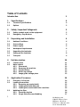
Table of Contents
Introduction 1
1 Specifications 4
1.1 Technical Specifications 4
1.2 Options 5
2 Safety / Important Safeguards 5
2.1 Safety symbols used on the equipment 5
2.2 Emergency Stop Buttons 5
3 Unpacking and Installation 6
3.1 Ambient Conditions 6
3.2 Surroundings 6
3.3 Power supply 6
3.4 Workspace Requirements 6
3.5 Unpacking the laminator 7
3.6 Setting up the laminator 8
3.7 Transport 9
4 Unit description 10
4.1 Control panel 11
4.2 Motor control 11
4.2.1 Slow-mode 12
4.2.2 Reversing the machine 12
4.2.3 Unwind brakes 13
4.2.4 Roller nip settings 13
4.2.5 Image guide storage place 13
5 Application Processes 14
5.1 Principle of a Process 14
5.2 Loading the machine 15
5.2.1 Removing an unwind shaft 15
5.2.2 Loading shaft with film rolls 15
5.2.3 Loading the unwind shaft into a machine 16
5.3 Webbing the films 1
6
5.3.1 Preset the tension 16
5.3.2
Single Sided Process Webbing 17
MyBinding.com
5500 NE Moore Court
Hillsboro, OR 97124
Toll Free: 1-800-944-4573
Local: 503-640-5920

3
English
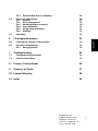
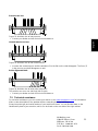
5.3.3 Double Sided Process Webbing 18
5.4 Processes and settings 19
5.4.1 General 19
5.4.2 Pre-coating panels 19
5.4.3 Mounting images or decals 20
5.4.4 Over-lamination 21
5.4.5 Single-sided lamination 21
5.4.6 Decaling 22
5.5 Unloading 2
2
6 Cleaning/maintenance 22
6.1 Cleaning the silicone covered rollers 23
6.2 Preventive maintenance 23
6.2.1 Auto-grip shafts 23
7 Troubleshooting 24
7.1 Troubleshooting Processes 24
7.2 Technical assistance 25
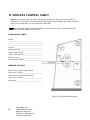
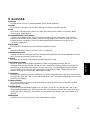
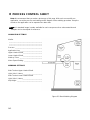
8 Process Control Sheet 26
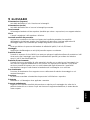
9 Glossary of Terms 27
10
Limited Warranty 28
11 Index 29
MyBinding.com
5500 NE Moore Court
Hillsboro, OR 97124
Toll Free: 1-800-944-4573
Local: 503-640-5920

4
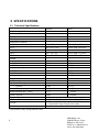
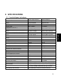
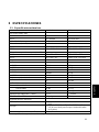
1 SPECIFICATIONS
1.1 Technical Specifications
Imperial Metric
Max. Working Width
54 EL 54" maximum 1400 mm max
65 EL 65" maximum 1651 mm max
Max. Speed 13.1 ft/min 4.0 m/min
Dimensions (HxWxD)
54 EL 48" x 71.3" x 24" 1220 x 1811 x 610 mm
65 EL 48" x 82.3" x 24" 1220 x 2090 x 610 mm
Shipping dimensions (HxWxD)
54 EL 58" x 74" x 29" 1473 x 1880 x 737 mm
65 EL 61" x 88" x 30" 1549 x 2235 x 762 mm
Weight
Net Weight
54 EL
325 lbs 147 kg
65 EL
430 lbs 195 kg
Shipping Weight
54 EL
434 lbs 197 kg
65 EL
544 lbs 247 kg
Maximum roll diameter
Unwind
8" 200 mm
Take-up
6" 150 mm
Maximum roll weight
Unwind 85 lbs 38.5 kg
Take-up 35 lbs 15.9 kg
Roller Opening (Min. – Max.) 0 – 1" 0 – 25 mm
Roller Pressure 3 lb/in 0.53 N/mm.
Electrical Specifications
US/Canada
115 VAC, 50/60Hz, 4A, 460W - NEMA 5-15 Plug
Europe
230 VAC, 50/60Hz, 2A, 460W - BS1363 Plug or
Continental Europe Plug (Schuko style)
Roller Construction Two silicone covered, steel rollers.
* Specifications may change without notice.
MyBinding.com
5500 NE Moore Court
Hillsboro, OR 97124
Toll Free: 1-800-944-4573
Local: 503-640-5920

5
English
1.2 Options
The 54/65 EL “A” version has several options available. They are:
Item Description Part number
1
54 EL Infeed Trough Option
5402A
2
65 EL Infeed Trough Option
6502A
3 Leveling feet Option 5406A
4
54 EL
-
1 Image Guide
5411A
5
65 EL-1 Image Guide
6511A
Note: Some options may be included with your model.
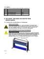
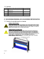
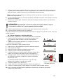
2 SAFETY / IMPORTANT SAFEGUARDS
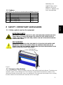
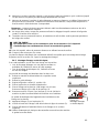
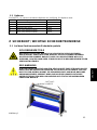
2.1 Safety symbols used on the equipment
ROTATING PARTS
MECHANICAL HAZARD. FAILURE TO USE CAUTION NEAR EXPOSED ROLLERS
COULD RESULT IN PHYSICAL INJURY. BE CAREFUL THAT ITEMS SUCH AS
LOOSE CLOTHING, LONG HAIR AND JEWELRY DO NOT BECOME ENTANGLED
IN ROTATING PARTS.
ESD WARNING
USE CAUTION NEAR ROLLERS. POSSIBILITY OF SHOCK BY ESD WITH SOME
MATERIALS. PLEASE USE PRECAUTIONS TO PREVENT ESD BUILD UP BY
PROPER MACHINE GROUNDING, MAINTAINING PROPER ROOM HUMIDITY AND
USING OTHER ANTI-STATIC MEASURES.
Figure 1
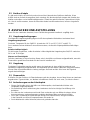
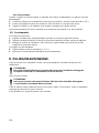
2.2 Emergency Stop Buttons
There are two buttons. They are located on the top of the left and right hand cabinets. The buttons are
red with a yellow, circular background. The Emergency stop buttons shut down the rotation of the
rollers and should only be used in case of an emergency. Once pressed, these buttons lock, and they
must be rotated to be reset before the machine can be used again.
EMERGENCY
STOP B
UTTONS
MyBinding.com
5500 NE Moore Court
Hillsboro, OR 97124
Toll Free: 1-800-944-4573
Local: 503-640-5920

6
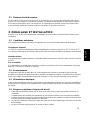
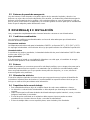
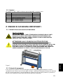
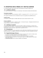
3 UNPACKING AND INSTALLATION
Please read and fully understand the entire manual before proceeding to use your laminator.
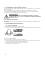
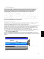
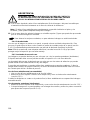
3.1 Ambient Conditions
The following environmental conditions are ideal for the best operation of the laminator.
Ambient Temperature
The best temperature for the 54/65 EL is between 16°C and 35°C (50°F and 95°F).
Do not expose the laminator to direct sunlight as output quality may be affected.
Relative humidity
For best results, the ambient relative humidity for the 54/65 EL should lie between 50% and 70%.
Water and moisture
If the laminator is installed in a damp room or near water, the electrical power supply must be in
accordance with the standards of the area.
3.2 Surroundings
Install the laminator in surroundings that are as clean and dust free as possible in order to obtain the
highest quality end product. The materials that are used on this laminator can have an electrostatic
charge and will attract dust, adversely affecting the output.
3.3 Power supply
Connect the machine in accordance with the details given on the identification plate attached to the
rear of the machine. Refer also to the technical specifications in this section for more information.
3.4 Workspace Requirements
• This unit should be situated away from heat sources such as heat registers or stoves.
• The laminator’s location or position should not interfere with its proper ventilation.
• There should be enough space around the laminator to feed-in, exit, and trim mounted and/or
laminated images.
• The background dust level must not exceed that found in a typical office/computer room
environment.
• The work area should be level, flat, and well lit.
MyBinding.com
5500 NE Moore Court
Hillsboro, OR 97124
Toll Free: 1-800-944-4573
Local: 503-640-5920

7
English
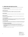
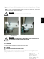
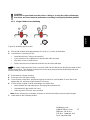
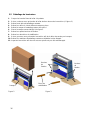
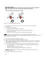
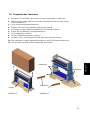
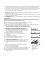
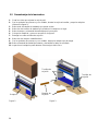
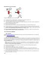
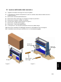
3.5 Unpacking the laminator
1. Cut the bands holding the box to the pallet.
2. With two people, carefully lift the box straight up over the machine (See figure 2).
3. Remove any loose packing material.
4. Remove two wood screws holding ramp in place.
5. Remove the ramp and packing around ramp.
6. Position ramp as shown in figure 3.
7. Remove 4 hold down bolts.
8. Remove 2 stabilizing blocks.
9. With 2 people, carefully push machine down ramp.
10. Remove remaining packing material and unpack the Take-up Tube.
11. Inspect the machine for any physical damage.
Figure 2 Figure 3
Ramp
Hold
Down
Bolts
Stabilizing
Blocks
Hold
Down
Bolts
MyBinding.com
5500 NE Moore Court
Hillsboro, OR 97124
Toll Free: 1-800-944-4573
Local: 503-640-5920

8
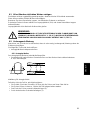
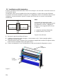
3.6 Setting up the laminator
Your 54/65 EL should be setup at the place where it will be used. The area must be a flat level
surface.
The machine must be installed next to a power outlet. The plug and the outlet must be easily
accessible. Please ensure that you plug your laminator into a grounded outlet. The laminator should
only be connected to a power supply outlet able to safely supply the voltage and amperage marked
on the ratings label.
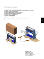
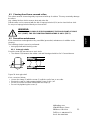
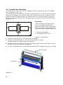
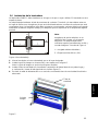
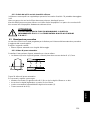
Note:
Make sure that the machine, in its final
location, has adequate space. You will
need room to feed, receive and trim
images. See Figure 4.
L = Maximum board length,
S = Minimum space 60 cm.(24").
Figure 4: Working Space
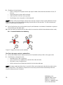
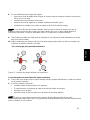
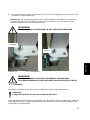
1. Move the machine to the designated working space.
2. Install Image Guide on table as shown in figure 5.
Note: Image Guide is optional on some models.
3. Install Take-up Tube onto right side first compressing spring on the right side then inserting left
side onto drive (figure 5).
4. Plug the power cable into the grounded outlet with appropriate service.
Figure 5
Image
Guide
Take-up
Tube
MyBinding.com
5500 NE Moore Court
Hillsboro, OR 97124
Toll Free: 1-800-944-4573
Local: 503-640-5920

9
English
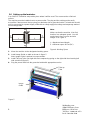
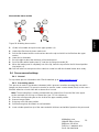
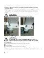
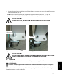
5. Lock machine in place with foot by stepping on the front caster’s locking mechanisms. (See figure
6.)
Note: An uneven floor may affect lamination quality. In the case of an uneven floor, please contact
technical service for the machine leveling option.
WARNING:
MACHINE MUST BE SECURED IN PLACE BEFORE USING.
Figure 6
WARNING:
MAKE SURE THE POWER SUPPLY CABLE AND/OR THE EXTENSION CABLE IS
NOT BLOCKING YOUR WAY AROUND THE MACHINE.
3.7 Transport
The machine can be transported on a smooth surface on its casters.
CAUTION:
Unlock the wheels before moving the machine.
When moving the machine on rough surfaces or over long distances, use the original pallet and
packing material and move it with a pallet truck or forklift.
Locking Lever
OFF
ON
MyBinding.com
5500 NE Moore Court
Hillsboro, OR 97124
Toll Free: 1-800-944-4573
Local: 503-640-5920

10
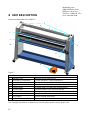
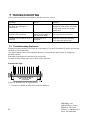
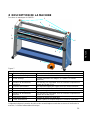
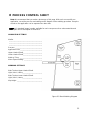
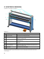
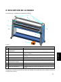
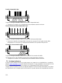
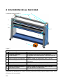
4 UNIT DESCRIPTION
Features and benefits of the 54/65 EL:
Figure 7
Identification of parts
1 Wind-up tube Wind-up for the release-liner
2 Emergency stop buttons To stop machine in case of emergency
3 Image guide To help start images (Optional on some models.)
4 Upper unwind shaft The shaft is suitable for material with a 3-inch core
5 Unwind brake A simple means of setting the unwind tension
6 Control panel Controls rotation of the rolls and standby
7 Nip Hand Wheel To adjust the gap between the rollers
8 Lower unwind shaft The shaft is suitable for material with a 3-inch core
9 Foot switch Used to engage slow mode
10 In-feed Table Flat surface to rest material to be worked on
T
he Ratings/Serial label is located on the rear side of the machine by the power inlet.
3
5
7
4
9
8
1
2
6
10
MyBinding.com
5500 NE Moore Court
Hillsboro, OR 97124
Toll Free: 1-800-944-4573
Local: 503-640-5920

11
English
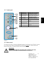
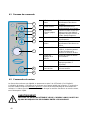
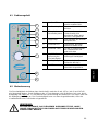
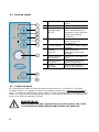
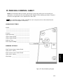
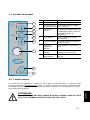
4.1 Control panel
F
igure 8
4.2 Motor control
The speed of the rollers is continuously adjustable between 0 and 4 m/min (0 and 13 ft/min). Pressing
the button runs the rollers in forward direction, pressing and holding the button reverses the
direction of the rollers. The stop key halts the roller movement.
WARNING:
CARE MUST BE TAKEN NOT TO HAVE LOOSE CLOTHING, LONG HAIR,
JEWELRY AND FINGERS PINCHED BETWEEN THE ROLLERS.
1 Forward LED Lit when drive runs forward
2 Forward Button Push button for forward
3 LED optical
safety system
Lit when light beam is clear.
Flashing when emergency
stop button depressed.
4 Stop Button Push button to stop drive
5 Reverse LED Lit when drive runs reverse
6 Reverse Button Push button and hold for
reverse
7 Speed
adjustment knob
Adjust roller speed
8 Standby Button Toggle on/off (press 2
seconds)
9 Power LED Lit when machine is on
1
2
3
4
5
6
7
8
9
MyBinding.com
5500 NE Moore Court
Hillsboro, OR 97124
Toll Free: 1-800-944-4573
Local: 503-640-5920

12
4.2.1 Slow-mode
The machine has a slow-mode, which can be activated by pressing the foot switch. To maintain slow-
mode, keep the foot switch pressed. Slow-mode must be used when the In-feed Table is in the upper
position. Slow mode is recommended whenever running material with the Image Guide removed.
The speed can be adjusted when running in slow mode. The speed can be adjusted down to zero, but
cannot be adjusted any higher than maximum allow in slow mode (1 mpm or 3 fpm). The position of
the speed pot will be about the same as in normal mode to produce the same speed. Another benefit
to this feature is the speed will not increase if going slower the preset maximum speed when entering
slow mode.
WARNING:
IF RUNNING IN SLOW-MODE, INTERRUPTING THE PHOTO ELECTRIC EYES
DOES NOT STOP THE MACHINE. IN SLOW-MODE, AN AUDIBLE BEEP WILL BE
HEARD, AND THE ROLLER SPEED WILL BE DECREASED. RELEASING THE
FOOT SWITCH STOPS THE MACHINE.
To Change from slow-mode to normal run mode without stopping (to prevent a stop mark):
• During slow mode (keep the foot switch pressed), press and hold the (forward) button on the
control panel.
• Next, release the foot switch. The machine will run at the pre-set speed.
• Finally, release the (forward) button.
To Change from normal run mode to slow-mode without stopping:
• Press the foot switch
Note: Releasing the foot switch will stop the machine.
4.2.2 Reversing the machine
WARNING:
KEEP CLEAR OF THE REAR SIDE NIP WHEN RUNNING IN REVERSE MODE.
To reverse the rotation of the rollers, press the (reverse) button. As long as the button is pressed,
the machine will run in reverse direction, at a speed of about 1 m/min. Releasing the button will stop
the machine.
The rotation of the rollers will stop when:
• The photoelectric eyes in front of the main rollers are interrupted.
Note: This does NOT happen when the foot switch is used (slow-mode).
• An emergency stop button is pressed.
• The foot switch is pressed for a short moment.
• Excessive unwind tensions are set (the motor will be shut off electronically and the forward LED
will blink, press the stop button on the control panel to reset).
• The stop button on the control panel is pressed.
MyBinding.com
5500 NE Moore Court
Hillsboro, OR 97124
Toll Free: 1-800-944-4573
Local: 503-640-5920

13
English
4.2.3 Unwind brakes
Tighten the unwind brake so that it applies sufficient tension to laminate. Turning the knurled brake
collar in a counter-clockwise direction increases the breaking tension applied on the laminate. Turning
the collar clockwise decreases the tension. The best setting for the brake tension is determined by the
materials you are using and is learned through experience.
4.2.4 Roller nip settings
Whenever you mount onto a board, etc., it is important to adjust the rollers to create a gap nearly
equal to the thickness of the substrate being used. This is done so that anything passing between the
rollers will receive the right amount of pressure to prevent damage to the substrate being mounted
(and possibly the rollers).
Turning the Nip Hand Wheel counterclockwise (CCW) lowers the top roller, and clockwise (CW)
raises the top roller.
How to set the nip:
Determine the thickness of the substrate that you will use for mounting. Pre-set the nip height by
turning Nip Hand Wheel CW until the nip height indicator is above the board thickness.
Insert the front edge of the substrate into the nip by hand. Lower the top roller by turning the Nip Hand
Wheel CCW until top roller contacts the substrate with enough pressure that the substrate cannot be
moved side to side. Use reverse button to remove substrate from nip if needed.
To run films, rotate the nip hand wheel CCW until the nip is fully closed then continue until the Nip
Hand Wheel turns freely.
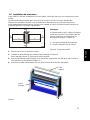
4.2.5 Image guide storage place
When not in use, the Image Guide can be stored on the upper cross brace or alternately on the lower
cross brace(figure 9). Note: Image Guide is optional on some models.
Image Guide
Upper Cross Brace
Figure 9
MyBinding.com
5500 NE Moore Court
Hillsboro, OR 97124
Toll Free: 1-800-944-4573
Local: 503-640-5920

14
5 APPLICATION PROCESSES
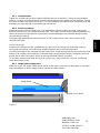
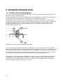
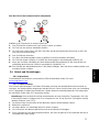
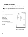
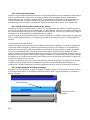
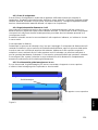
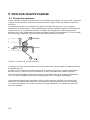
5.1 Principle of a Process
In all processes the materials are fed through the nip from the front side to be joined together by
pressure.
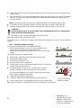
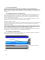
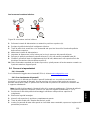
A process that makes maximum use of the machine is shown in Figure 10. Shown is a double sided
laminating (decaling) process.
The top coating film is a pressure sensitive film with release liner (3) taken from a supply roll on the
(rear) upper unwind shaft (5). The bottom coating film is a pressure sensitive (mounting) film taken
from a supply roll on the lower unwind shaft (7). Some models have a splitter bar (8) to help in the
removal of release liners.
Figure 10: Creating a Decal.
The image that has to be laminated is fed between the main rollers (1) via the in-feed table (2).
When using a pressure sensitive laminate, it often has a release liner (3) that has to be removed.
This release liner is rolled up onto the wind-up shaft (4) in the upper section.
A mounting film has adhesive on both sides and release liner on just one side. This release liner has
to stay on until the image is mounted.
The following steps outline the basic procedure that has to be used for loading materials, webbing the
laminator and setting the brake tension for the materials you will be using. To load and unload the
material shafts, it is necessary to access the machine from the rear side.
8
MyBinding.com
5500 NE Moore Court
Hillsboro, OR 97124
Toll Free: 1-800-944-4573
Local: 503-640-5920

15
English
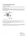
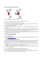
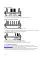
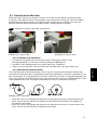
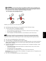
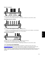
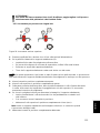
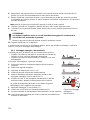
5.2 Loading the machine
Select the film(s) that you will use on the top (and bottom) of the images. It is best practice to make
sure that both laminate and media are matched in size to prevent problems when laminating. This
way the media can be trimmed with a border, but waste is reduced.
Always work in the center of the machine.
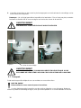
Figure 11: Interlock up Figure 12: Interlock down
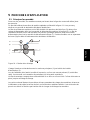
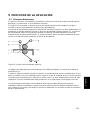
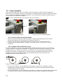
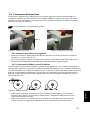
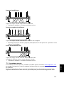
5.2.1 Removing an unwind shaft
• Remove the desired supply shaft (top or bottom) by pushing the interlock bracket (1) to the up
position (Figure 11).
• Slide the autogrip shaft to the right against the spring pressure.
• Lift the leftside of the shaft away from the laminator first then the right.
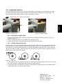
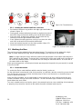
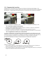
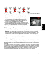
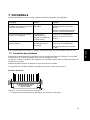
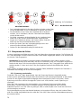
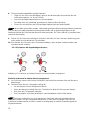
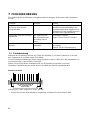
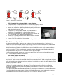
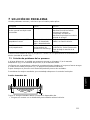
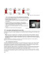
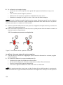
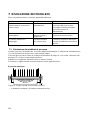
5.2.2 Loading shaft with film rolls
The film roll is put on the shaft depending on the type of film and the use in the upper or lower section
of the machine. In general, pressure sensitive film with release liner (A) is rolled up with the liner (3)
and adhesive (2) to the outside of the film (1), whereas film without release liner (C) has its adhesive
layer to the inside of the film. However, North American pressure sensitive films, in general, have the
release liner on the inside of the film (B).
Figure 13: Film rolls.
• In the upper section, the adhesive (2) side in contact with the image and the release liner (3) must
be on the top when unwinding the film to the front of the machine.
• In the lower section, the adhesive (2) side in contact with the image must be on the bottom when
unwinding the film to the front of the machine.
1
MyBinding.com
5500 NE Moore Court
Hillsboro, OR 97124
Toll Free: 1-800-944-4573
Local: 503-640-5920
Seite wird geladen ...
Seite wird geladen ...
Seite wird geladen ...
Seite wird geladen ...
Seite wird geladen ...
Seite wird geladen ...
Seite wird geladen ...
Seite wird geladen ...
Seite wird geladen ...
Seite wird geladen ...
Seite wird geladen ...
Seite wird geladen ...
Seite wird geladen ...
Seite wird geladen ...
Seite wird geladen ...
Seite wird geladen ...
Seite wird geladen ...
Seite wird geladen ...
Seite wird geladen ...
Seite wird geladen ...
Seite wird geladen ...
Seite wird geladen ...
Seite wird geladen ...
Seite wird geladen ...
Seite wird geladen ...
Seite wird geladen ...
Seite wird geladen ...
Seite wird geladen ...
Seite wird geladen ...
Seite wird geladen ...
Seite wird geladen ...
Seite wird geladen ...
Seite wird geladen ...
Seite wird geladen ...
Seite wird geladen ...
Seite wird geladen ...
Seite wird geladen ...
Seite wird geladen ...
Seite wird geladen ...
Seite wird geladen ...
Seite wird geladen ...
Seite wird geladen ...
Seite wird geladen ...
Seite wird geladen ...
Seite wird geladen ...
Seite wird geladen ...
Seite wird geladen ...
Seite wird geladen ...
Seite wird geladen ...
Seite wird geladen ...
Seite wird geladen ...
Seite wird geladen ...
Seite wird geladen ...
Seite wird geladen ...
Seite wird geladen ...
Seite wird geladen ...
Seite wird geladen ...
Seite wird geladen ...
Seite wird geladen ...
Seite wird geladen ...
Seite wird geladen ...
Seite wird geladen ...
Seite wird geladen ...
Seite wird geladen ...
Seite wird geladen ...
Seite wird geladen ...
Seite wird geladen ...
Seite wird geladen ...
Seite wird geladen ...
Seite wird geladen ...
Seite wird geladen ...
Seite wird geladen ...
Seite wird geladen ...
Seite wird geladen ...
Seite wird geladen ...
Seite wird geladen ...
Seite wird geladen ...
Seite wird geladen ...
Seite wird geladen ...
Seite wird geladen ...
Seite wird geladen ...
Seite wird geladen ...
Seite wird geladen ...
Seite wird geladen ...
Seite wird geladen ...
Seite wird geladen ...
Seite wird geladen ...
Seite wird geladen ...
Seite wird geladen ...
Seite wird geladen ...
Seite wird geladen ...
Seite wird geladen ...
Seite wird geladen ...
Seite wird geladen ...
Seite wird geladen ...
Seite wird geladen ...
Seite wird geladen ...
Seite wird geladen ...
Seite wird geladen ...
Seite wird geladen ...
Seite wird geladen ...
Seite wird geladen ...
Seite wird geladen ...
Seite wird geladen ...
Seite wird geladen ...
Seite wird geladen ...
Seite wird geladen ...
Seite wird geladen ...
Seite wird geladen ...
Seite wird geladen ...
Seite wird geladen ...
Seite wird geladen ...
Seite wird geladen ...
Seite wird geladen ...
Seite wird geladen ...
Seite wird geladen ...
Seite wird geladen ...
Seite wird geladen ...
Seite wird geladen ...
Seite wird geladen ...
Seite wird geladen ...
Seite wird geladen ...
Seite wird geladen ...
Seite wird geladen ...
Seite wird geladen ...
Seite wird geladen ...
Seite wird geladen ...
Seite wird geladen ...
Seite wird geladen ...
Seite wird geladen ...
Seite wird geladen ...
-
 1
1
-
 2
2
-
 3
3
-
 4
4
-
 5
5
-
 6
6
-
 7
7
-
 8
8
-
 9
9
-
 10
10
-
 11
11
-
 12
12
-
 13
13
-
 14
14
-
 15
15
-
 16
16
-
 17
17
-
 18
18
-
 19
19
-
 20
20
-
 21
21
-
 22
22
-
 23
23
-
 24
24
-
 25
25
-
 26
26
-
 27
27
-
 28
28
-
 29
29
-
 30
30
-
 31
31
-
 32
32
-
 33
33
-
 34
34
-
 35
35
-
 36
36
-
 37
37
-
 38
38
-
 39
39
-
 40
40
-
 41
41
-
 42
42
-
 43
43
-
 44
44
-
 45
45
-
 46
46
-
 47
47
-
 48
48
-
 49
49
-
 50
50
-
 51
51
-
 52
52
-
 53
53
-
 54
54
-
 55
55
-
 56
56
-
 57
57
-
 58
58
-
 59
59
-
 60
60
-
 61
61
-
 62
62
-
 63
63
-
 64
64
-
 65
65
-
 66
66
-
 67
67
-
 68
68
-
 69
69
-
 70
70
-
 71
71
-
 72
72
-
 73
73
-
 74
74
-
 75
75
-
 76
76
-
 77
77
-
 78
78
-
 79
79
-
 80
80
-
 81
81
-
 82
82
-
 83
83
-
 84
84
-
 85
85
-
 86
86
-
 87
87
-
 88
88
-
 89
89
-
 90
90
-
 91
91
-
 92
92
-
 93
93
-
 94
94
-
 95
95
-
 96
96
-
 97
97
-
 98
98
-
 99
99
-
 100
100
-
 101
101
-
 102
102
-
 103
103
-
 104
104
-
 105
105
-
 106
106
-
 107
107
-
 108
108
-
 109
109
-
 110
110
-
 111
111
-
 112
112
-
 113
113
-
 114
114
-
 115
115
-
 116
116
-
 117
117
-
 118
118
-
 119
119
-
 120
120
-
 121
121
-
 122
122
-
 123
123
-
 124
124
-
 125
125
-
 126
126
-
 127
127
-
 128
128
-
 129
129
-
 130
130
-
 131
131
-
 132
132
-
 133
133
-
 134
134
-
 135
135
-
 136
136
-
 137
137
-
 138
138
-
 139
139
-
 140
140
-
 141
141
-
 142
142
-
 143
143
-
 144
144
-
 145
145
-
 146
146
-
 147
147
-
 148
148
-
 149
149
-
 150
150
-
 151
151


MyBinding SEAL 54EL 1 Benutzerhandbuch
- Kategorie
- Laminatoren
- Typ
- Benutzerhandbuch
in anderen Sprachen
- English: MyBinding SEAL 54EL 1 User manual
- français: MyBinding SEAL 54EL 1 Manuel utilisateur
- español: MyBinding SEAL 54EL 1 Manual de usuario
- italiano: MyBinding SEAL 54EL 1 Manuale utente
Verwandte Artikel
-
MyBinding MBM Destroyit 4108 Level P-2 Strip-Cut Paper Shredder Benutzerhandbuch
-
-
-
-
Andere Dokumente
-
Hilti Rollen TS20E Benutzerhandbuch
-
 UNITED OFFICE ULG 350 A1 Operating Instructions Manual
-
Kompernass Laminator KH 4412 Benutzerhandbuch
-
UNITED OFFICE KH 4418 LAMINATOR Operating Instructions Manual
-
UNITED OFFICE ULG 300 A1 Operating Instructions Manual
-
 SEAL Image 6500 Bedienungsanleitung
-
Sammic FMI-41 (5500089) Bedienungsanleitung
-
GYS PAINT-THICKNESS SENSOR Bedienungsanleitung
-
Alliance Laundry Systems RI1400/25 F Benutzerhandbuch
-
ALLIANCE RI1400/25 Benutzerhandbuch

