
DOC024.98.93034
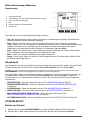
POLYMETRON Model
9240 Multi-Channel Sodium
Analyzer
05/2018, Edition 13
Basic User Manual
Allgemeines Benutzerhandbuch
Manuel d'utilisation de base
Manual básico del usuario
Manuale di base per l'utente
Podstawowa instrukcja obsługi
Grundlæggende brugervejledning
Allmän användarhandbok
Osnovni uporabniški priročnik
Alapvető felhasználói kézikönyv
Βασικό εγχειρίδιο χρήσης
Temel Kullanıcı Kılavuzu

English..............................................................................................................................3
Deutsch.......................................................................................................................... 26
Français......................................................................................................................... 51
Español.......................................................................................................................... 75
Italiano............................................................................................................................ 99
Polski............................................................................................................................ 123
Dansk............................................................................................................................148
Svenska....................................................................................................................... 172
Slovenski..................................................................................................................... 195
Magyar......................................................................................................................... 218
Ελληνικά...................................................................................................................... 242
Türkçe...........................................................................................................................268
2

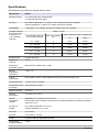
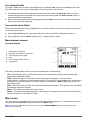
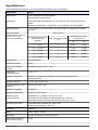
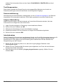
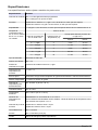
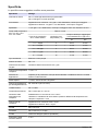
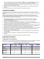
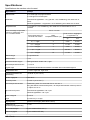
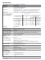
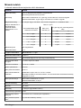
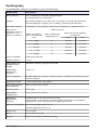
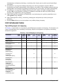
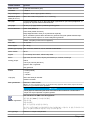
Specifications
Specifications are subject to change without notice.
Specification Details
Measuring range 0 to 10,000 ppb freely programmable
0 to 200 ppm with K-Kit option
Accuracy Non-cationic application: ± 0.1 ppb or ± 5% of reading, whichever is greater
Cationic application: ± 2 ppb or 5% reading, whichever is greater
Repeatability < 0.02 ppb or 1.5% reading, whichever is greater within 10°C variation
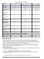
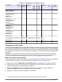
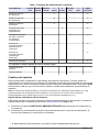
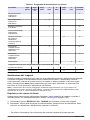
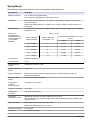
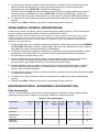
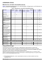
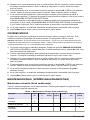
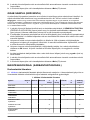
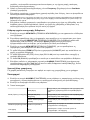
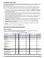
Average response
times at 25°C with
a maximum ΔT
=15°C between
channels
T90% ≤ 10 min
Concentration step from
one channel to another
Max. temp variation
(°C)
Time to reach accuracy 0.1 ppb or 5%
up down
0.1 ↔ 5 ppb 3 9 min 27 min
0.1 ↔ 50 ppb 3 11 min 41 min
0.1 ↔ 200 ppb 3 9 min 45 min
< 0.1 ↔ 1 ppb 3 29 min 36 min
0.1 ↔ 50 ppb 15 11 min 41 min
Electrode type pH glass electrode
Number of
channels
1 to 4
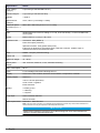
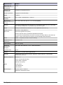
Interference
phosphate 10 ppm
Measurement variation less 0.1 ppb
Sample
temperature
interference
< 0.5% / °C
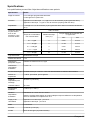
Typical
environment
Power station / indoor / demineralized water plant or instrumentation room
Suspended solids < 2 NTU, no oil, no grease
Temperature range
for storage
-20 to 60°C (2 to 140°F)
Relative humidity 10 to 80%
Ambient
temperature
5 to 50°C (41 to 122°F)
Sample
temperature
variation
Stabilization in 10 mins from 15°C to 30°C
Use the static heat exchanger system when the temperature difference between samples is
higher than 15°C
pH range of
sample
Non-cationic application: 6 to 10 pH
Cationic application: 2 to 10 pH
Flow rate 6 to 9 L/hour
Pressure 0.2 to 6 bar (3 - 87 psi)
Acidity Less than 250 ppm (equivalent CaCO
3
)
Power supply
voltage fluctuation
± 10%
English 3

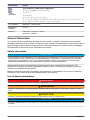
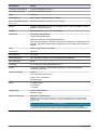
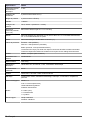
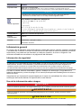
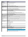
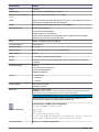
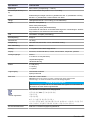
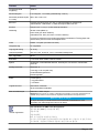
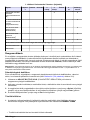
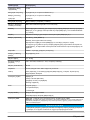
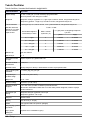
Specification Details
Over voltage
category
2 (according to standard EN 61010-1)
Pollution degree 2 (according to standard CEI 664)
Altitude < 2000 m
Measurement
category
Cat II, Class 1 (overvoltage < 1500V)
Maximum panel
dimension (H x L x
D)
850 x 450 x 252.5mm [33.46 x 17.71 x 9.94in]
Inlet Simple fittings for 6 mm O.D. tubing or ¼" O.D. in PE-low density. ¼" OD in PHED-PTFE-
SS as option
Outlet Barbed stem for 12 mm (½" I.D.) hose
Protection rate Transmitter: IP65 (NEMA 4)
Panel: IP50 (dust protection)
Optional Enclosure: IP54 (splash water proof)
Instrument is designed to avoid DIPA vapor inside the enclosure. All DIPA vapor is
collected and sent to the instrument drain
Cell PMMA - compact (minimum tubing)
Flame rate Conform UL
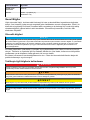
Maximum weight 15 - 30 Kg
Mains power
supply
100 - 240 VAC, 50-60 Hz, ± 10%, automatic switching
Max. consumption 80 VA
Fuse 5 x 20 cartridge T2AL-250V following CEI127
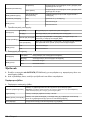
Display Curve trend, Last Cal Date, Historical, Concentration, Temperature, Potential
Analog outputs Number: 6
4-20 or 0-20 mA (650 ohms)
Linear / Dual / Logarithm
Event indication
Relays 4 x Relay (conc)
1 x Warning
1 x System
Logic input Active / Inactive channels
Remote AutoCal
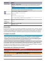
EMC requirements EN61326-1: EMC Directive
Note: This is a Class A product. In a domestic environment this product may cause radio interference in
which case the user may be required to take adequate measures.
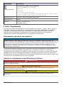
N O T I C E
Measurement variations of less than 5% of the full range can occur if the instrument is
subject to a strong electromagnetic field.
4 English

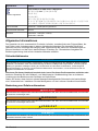
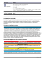
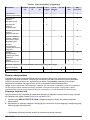
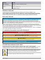
Specification Details
Korean
registration
User Guidance for EMC Class A Equipment
업무용을 위한 EMC 등급 A 장치에 대한
사용자 지침
사용자안내문
A 급 기기 ( 업무용 방송통신기자재 )
이 기기는 업무용 (A 급 ) 전자파적합기기로서 판매자 또는 사용자는 이 점을 주의하시기 바
라며 , 가정외의 지역에서 사용하는 것을 목적으로 합니다.
CE compliance EN61010-1: LVD Directive
International
standards
cETLus
Warranty Instrument: 1 year (EU: 2 years)
Electrodes: 6 months
General information
In no event will the manufacturer be liable for direct, indirect, special, incidental or consequential
damages resulting from any defect or omission in this manual. The manufacturer reserves the right to
make changes in this manual and the products it describes at any time, without notice or obligation.
Revised editions are found on the manufacturer’s website.
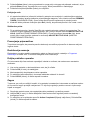
Safety information
N O T I C E
The manufacturer is not responsible for any damages due to misapplication or misuse of this product including,
without limitation, direct, incidental and consequential damages, and disclaims such damages to the full extent
permitted under applicable law. The user is solely responsible to identify critical application risks and install
appropriate mechanisms to protect processes during a possible equipment malfunction.
Please read this entire manual before unpacking, setting up or operating this equipment. Pay
attention to all danger and caution statements. Failure to do so could result in serious injury to the
operator or damage to the equipment.
Make sure that the protection provided by this equipment is not impaired. Do not use or install this
equipment in any manner other than that specified in this manual.
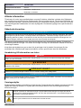
Use of hazard information
D A N G E R
Indicates a potentially or imminently hazardous situation which, if not avoided, will result in death or serious injury.
W A R N I N G
Indicates a potentially or imminently hazardous situation which, if not avoided, could result in death or serious
injury.
C A U T I O N
Indicates a potentially hazardous situation that may result in minor or moderate injury.
N O T I C E
Indicates a situation which, if not avoided, may cause damage to the instrument. Information that requires special
emphasis.
English 5

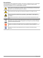
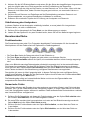
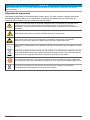
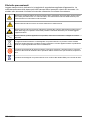
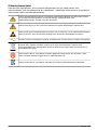
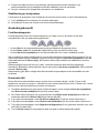
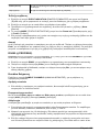
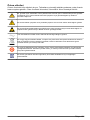
Precautionary labels
Read all labels and tags attached to the instrument. Personal injury or damage to the instrument
could occur if not observed. A symbol on the instrument is referenced in the manual with a
precautionary statement.
This is the safety alert symbol. Obey all safety messages that follow this symbol to avoid potential
injury. If on the instrument, refer to the instruction manual for operation or safety information.
This symbol indicates that a risk of electrical shock and/or electrocution exists.
This symbol indicates the presence of devices sensitive to Electro-static Discharge (ESD) and
indicates that care must be taken to prevent damage with the equipment.
This symbol, when noted on a product, indicates the instrument is connected to alternate current.
Electrical equipment marked with this symbol may not be disposed of in European domestic or
public disposal systems. Return old or end-of-life equipment to the manufacturer for disposal at no
charge to the user.
Products marked with this symbol indicates that the product contains toxic or hazardous substances
or elements. The number inside the symbol indicates the environmental protection use period in
years.
Products marked with this symbol indicates that the product conforms to relevant South Korean
EMC standards.
6 English

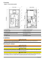
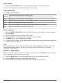
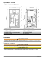
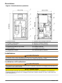
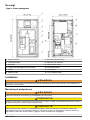
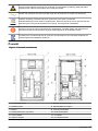
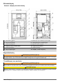
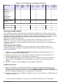
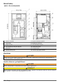
Overview
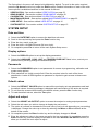
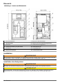
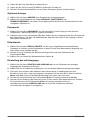
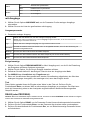
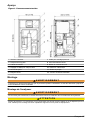
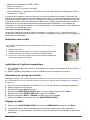
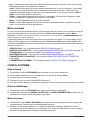
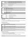
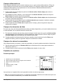
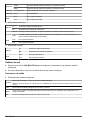
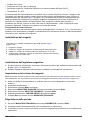
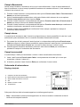
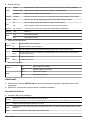
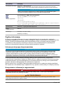
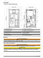
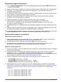
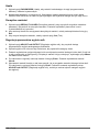
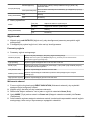
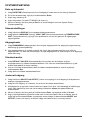
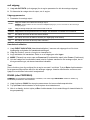
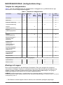
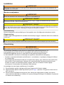
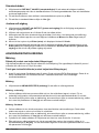
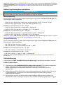
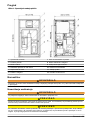
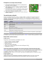
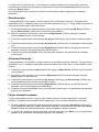
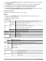
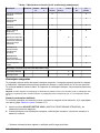
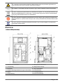
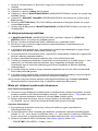
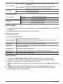
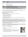
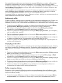
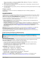
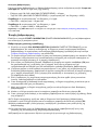
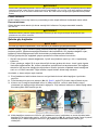
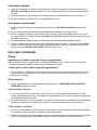
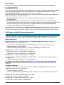
Figure 1 Front and rear panels
1 User interface 7 Frame for panel mounting
2 Overflow vessel 8 Reagent canister holder
3 Measuring cell 9 Local controller box
4 Flow rate adjustment for each channel 10 Electrolyte reservoir
5 Door lock 11 Pump box
6 Reagent shelf 12 Sample inlet valves
Installation
W A R N I N G
The analyzer should only be assembled by qualified staff. Mains power should only be connected once
installation has been completed and checked
Mounting the analyzer
W A R N I N G
Do not connect power prior to mounting and plumbing the instrument.
C A U T I O N
Personal injury hazard. Instruments or components are heavy. Use assistance to install or move. Make sure that
the wall mounting is able to hold 4 times the weight of the equipment.
C A U T I O N
Wherever the analyzer is to be mounted, it is important to note that it must be placed in an upright position with
the transmitter at the top. It is recommended to use a spirit level to ensure that the analyzer is correctly positioned
and not leaning to one side or forward. This is essential to guarantee the accuracy of the analyzer.
English 7

Panel mounting
Mount the analyzer using the fixation holes located around the outside of the analyzer.
Wall mounting
Use the wall mounting kit to fix the instrument to the wall. The distance between the two pieces is
460 mm.
C A U T I O N
It is extremely important to respect this gap of 460 mm to avoid bending the cabinet out of shape while fitting.
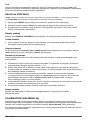
Mains power connection
W A R N I N G
No intervention should be made on the instrument without first switching off the power.
The electrical installation should be carried out by duly qualified personnel. A supply voltage of
100-240 VAC is acceptable without changing the configuration. The power supply terminals can be
removed from their housing to make connection easier.
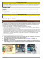
For safety reasons, it is imperative to respect the working procedure below:
• Use a three-wire power cable (live + neutral + earth), sized for supplying the required power.
• The instrument should be connected to the mains via a circuit-breaker or fuse whose value should
be less or equal to 20 A. It should be located in proximity and be identified. This connection should
cut-off the live and the neutral when electrical problems occur or when the user wishes to
intervene inside the instrument. On the other hand, the earth conductor should always be
connected.
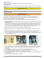
The main cabinet should be open with access to the interior.
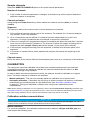
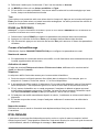
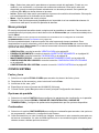
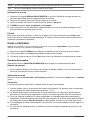
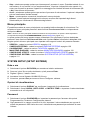
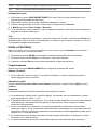
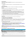
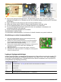
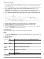
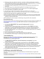
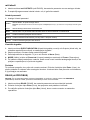
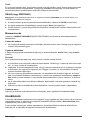
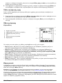
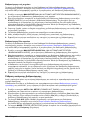
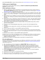
1. Pass the power cable through the cable gland located at the back left of the bottom of the
cabinet.
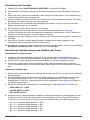
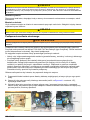
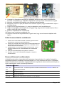
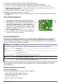
2. Open the back of the local controller box (No. 11 in Figure 1 on page 7) by unscrewing the
6 screws.
3. Unscrew the two holding screws on the upper left and right side of the box, and allow it to rotate
down to reveal the back of the transmitter. The cable gland for the power cable is located left and
nearest to you.
4. Unscrew the cable gland nut, pass the power cable through it, and then up through the cable
gland and into the transmitter (No. 2). Screw back the cable gland nut to secure the power cable.
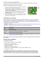
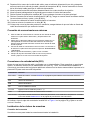
5. Open the transmitter front door by unscrewing the four holding screws.
6. Swing open the door (it is hinged to the left) to reveal the inside of the transmitter.
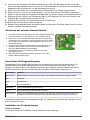
7. Remove the metallic shielding plate (No. 1) protecting access to the main board.
8. Remove the power supply connector (No. 3) and note where the earth, neutral and live (E, N, L)
must be connected.
9. Connect the power supply cables to the connector.
8
English

10. Put the connector back in place (No. 4).
11. Replace the metallic shielding plate, ensuring it is in front of the power cable just installed.
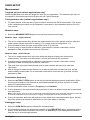
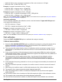
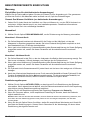
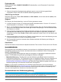
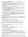
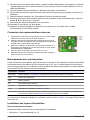
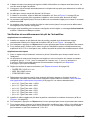
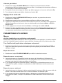
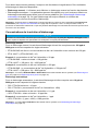
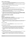
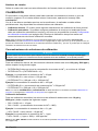
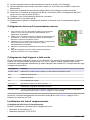
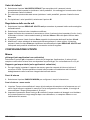
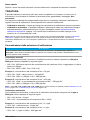
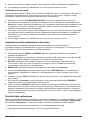
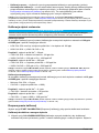
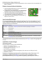
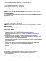
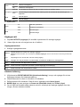
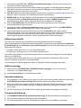
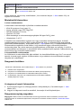
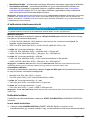
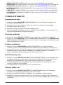
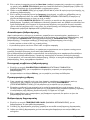
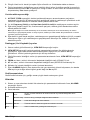
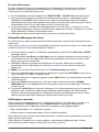
External communications connection
1. Run the communications cable through an external cable gland on
the bottom of the cabinet, and into the analyzer.
2. Pass it through the cable gland located right and farthest from you
on the base of the transmitter, so it appears inside the transmitter
through the left front cable gland.
3. Connect the communication cable as indicated. Connection is the
same on the CPU board for both the JBUS/ MODBUS and
PROFIBUS options.
4. Close the transmitter door and secure in place with the 4 screws.
5. Put the local controller box back in its normal position and secure in
place with the 2 holding screws.
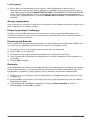
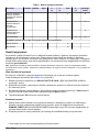
Input/Output connections
Before using any of the cable glands, perforate first with a screwdriver. To ensure a good seal, the
external diameter of the cables should be between 5 and 7 mm. The nomenclature given in the
connections column of the following table refers to the same nomenclature that is printed on the I/O
board against each available connection.
Connections Function
Re1 to Re6 User relays - see Alarms on page 17 for more information on the relays
Re7 Warning alarm
Re8 System alarm
In2 For remote calibration
In4 to In7 By-pass channel measurement (channel 4 - 1 respectively)
Iout0 Used for the current measurement signals
Iout1 to Iout7 Can be freely linked to different parameters like measurement, temperature - refer to the section
entitled mA outputs on page 18 for details
On completion, close the local controller box (No. 11 in Figure 1 on page 7) and secure in place with
the 6 screws.
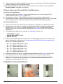
Sample tubes installation
Connecting the sample
Use new tubes for connections during installation
• Exterior Ø: 6 mm exactly (or ¼'')
• Material: polyethylene or PTFE or FEP
• Flow rate: 6 to 9 L/hour
• Pressure: 0.2 to 6 bar (8-100 psig)
• Sample acidity: sample acidity should not be more than 300 ppm CaCO
3
• Temperature: 5 to 45°C
At this stage of the installation, make sure that the flow valve is closed. Connect the pipes by
inserting them into the quick release connections found on the bottom of the analyzer under the
sampling block (No. 14 in Figure 1 on page 7). Be sure that the sample line is correctly flushed
before any connection to avoid particle injection into the hydraulic system. If particulate matter is
English
9

present in the sample, pre-filtration is necessary. A filter should be inserted in the sample line. One is
available as an option. Connect one inlet and one outlet per channel.
Connecting the drain tube
The drain outlet is located on the bottom of the analyzer. A 12 x 17 mm pipe is delivered with the
analyzer and should be connected to the drain outlet at one end and the other fed to a drain for
sample evacuation.
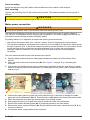
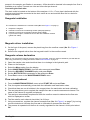
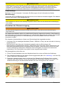
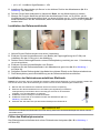
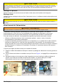
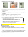
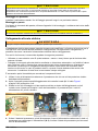
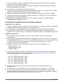
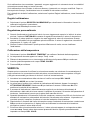
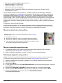
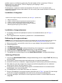
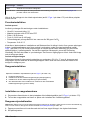
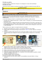
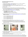
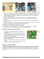
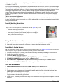
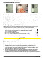
Reagents installation
The canisters are installed in the canister holder (No. 10 in Figure 1 on page 7).
1. Prepare the reagents.
2. Install and connect the conditioning solution (diisopropylamine).
3. Install and connect the reactivation solution (blue R label).
4. If you have this option, install and connect the auto calibration solution
(yellow CAL label).
Magnetic stirrer installation
1. On the front of the panel, remove the plastic bag from the overflow vessel (No. 5 in Figure 1
on page 7).
2. Remove the magnetic stirrer from the bag and install it in the overflow vessel.
Reagents volume declaration
Note: As you will now be using the analyzer menus to input data, it may be useful to familiarize yourself with the
data entry procedures by reading the section entitled User interface on page 12.
1. Open the sample valve and check that there is no leakage in the hydraulic path.
2. Power on the analyzer.
3. Select the Menu option from the display.
4. Select MAINTENANCE/DIAG. from the main menu and press Enter.
5. Select the REAGENT CHANGES option and press Enter.
6. Set the BOTTLES FULL parameter to Yes and press Enter.
7. Press Esc to return to the MAINTENANCE/DIAG. menu.
Flow rate adjustment
1. From the MAINTENANCE/DIAG. menu select START UP and press Enter.
2. First, the system automatically primes both the calibration and reactivation tubes.
3. Check that there are no air bubbles in the reagent tubes for reactivation and auto calibration.
4. The next step allows you to regulate the sample flow rate on each measurement channel. The
name of the channel to regulate is displayed.
5. The analyzer automatically empties and refills the overflow vessel to determine the flow rate
which is displayed on screen.
6. The flow rate for each channel should be 6 to 9 L/hour.
7. Using a screwdriver, regulate the channel’s sample flow (No. 3 in Figure 1 on page 7) by turning
counter-clockwise to increase the flow rate or clockwise to decrease the flow rate.
8. The process is repeated until the flow is correctly regulated for the channel. At this point select
OK.
10
English

9. The system then allows you to regulate the next channel until all flow rates have been set for the
configured channels.
10. Once all flow rates for the configured channels have been set, an Action completed message
will be displayed. Select Esc to exit.
Sample pH conditioning check
Non-cationic applications
1. Install a calibrated pH sensor in the center position of the measurement chamber which is
normally used for the ISE sodium electrode (No. 1 in Figure 1 on page 7).
2. On the analyzer, press Start on the main menu to start the measurement process.
3. For each channel, check that the pH value of the sample after conditioning is greater than 10.5. If
not, check the quality of the conditioning product used.
Cationic applications
1. With a calibrated pH sensor, measure the pH of the sample for each channel outside of the
analyzer.
2. The analyzer measurement sequence will be factory set depending on the number of configured
channels (e.g. 1 2 3 4 * for a 4-channel analyzer or 1 2 * for a 2-channel analyzer). Verify this
sequence is correctly setup (see Sequence on page 19 for more details).
3. Set the following measurement timings (see Measure steps on page 16):
• CYCLE TIME to 11 min
• ON LINE MEAS to 8 min
• SEARCH STAB to No
4. For each channel, determine the gas injection time ratio depending on the sample pH. Enter this
value into the analyzer as described in Total gas/water ratio (cationic applications only)
on page 16. The standard values are:
• pH = 2.0 - Tgas/Twater ratio = 180%
• pH = 2.3 - Tgas/Twater ratio = 80%
• pH = 2.6 - Tgas/Twater ratio = 50%
• pH = 2.9 - Tgas/Twater ratio = 30%
• pH = 3.5 - Tgas/Twater ratio = 15%
• pH = 4.0 - Tgas/Twater ratio = 10%
5. Install the same pH sensor in the center position of the measurement chamber (No. 2 in Figure 1
on page 7).
6. On the analyzer, press Start on the main menu to start the measurement process.
7. For each channel, measure the pH in the conditioned sample to check if the pump ratios are
efficient enough to obtain a pH of around 11.0. If necessary, update the ratio to maintain a final
constant pH of 11.0 ± 0.2.
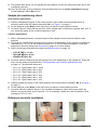
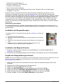
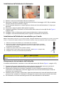
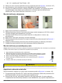
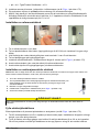
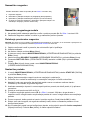
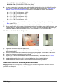
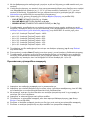
Reference electrode installation
English
11

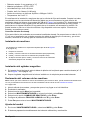
1. Remove the reference sensor from its box.
2. Remove the plastic reservoir from the bottom (the storage solution is KCl 3M) and install the O-
ring as shown.
3. With care, turn the bottom electrolyte tube ferrule with a maximum ¼ turn to lock it.
4. Remove the plastic plug on the entry port.
5. Install the reference electrode in the extreme left measurement chamber (No. 2 in Figure 1
on page 7).
6. Connect the reference cable (the one without the blue label on it) to the reference electrode.
7. Connect the electrolyte tube to the entry port on the reference electrode.
Sodium ion selective electrode installation
Note: It is critical to preserve the integrity of the sodium ion selective electrode as much as possible. This is why
this electrode must be installed at the very last moment after all other adjustments.
1. Remove the sodium ion selective sensor from its box.
2. Remove the plastic reservoir from the bottom (the storage solution is standard tap
water) and shake gently (as you would a thermometer) to dispose of any bubbles.
3. Install the O-ring as indicated right.
4. Install the ISE in the center position of the measurement chamber (No. 1 in Figure 1
on page 7).
5. Connect the AS7 cable (with the blue label) to the electrode.
C A U T I O N
After the electrodes installation, it is very important that none of the electrode heads are touching the bottom part
of the measuring cell.
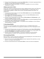
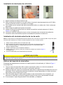
Fill electrolyte reservoir
The electrolyte reservoir is located at the back of the analyzer (No. 12 in Figure 1 on page 7).
1. Take the KCl electrolyte bottle and insert the tip of the tapered spout into the reservoir inlet tube
as far as it will go but without exerting any extra pressure.
2. Squeeze on the bottle as many times as necessary to fill the reservoir to about 3/4 of its capacity.
If you have any difficulty filling the reservoir, raise the spout of the bottle very slightly to avoid an
airlock.
3. Using thumb and forefinger, pump on the electrolyte tube between the reservoir and the
reference electrode to remove any air bubbles that may have formed.
4. If necessary, clean any KCl drops from the analyzer and the reservoir.
Analyzer stabilization
At this stage the analyzer has been completely installed, but needs to run for a period of time to
stabilize.
1. Press Start on the main menu to start the measurement process.
2. Leave the system to run for a couple of hours before starting any calibrations.
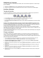
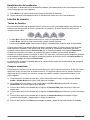
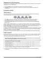
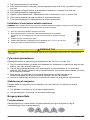
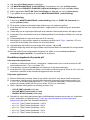
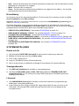
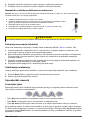
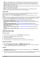
User interface
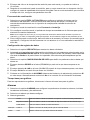
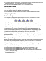
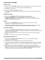
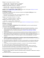
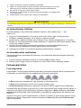
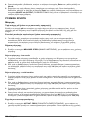
Function keys
The display panel has 5 function keys (illustrated below) to allow menu option selection, field
selection, and data entry options.
12
English

• The Esc key cancels data input or goes back to the previous screen.
• The Enter key validates the input and goes on to the next step
• The Up Arrow keys select the option displayed immediately above them on the screen.
When a screen requiring data entry is displayed, the first editable field is always highlighted. To
select other fields on the screen, scroll through them by pressing the Up Arrow function key under
the Select option. As each field is selected, the data element available for update is highlighted.
The same is also true when a menu is displayed. In this case, the first available option is always
highlighted. Scroll to the required option by pressing the Up Arrow function key under the Select
option.
Data entry is effected in a variety of ways depending on the characteristics of the data field being
accessed.
Numeric fields
These fields require that the user enter one or more numeric values into a field. The type of field
determines the available input. In some fields only digits 0 through 9 would be available to select
whereas in other fields the decimal point and/or minus sign may also be available.
1. For data elements such as these, press the function key under either the Up Arrow or Down
Arrow options to initiate data entry.
2. The first digit will then be highlighted, and a new Right Arrow option replaces the Select option
at the bottom of the screen.
3. Press the function key under the Up Arrow option to increase the value of the field by 1.
4. Press the function key under the Down Arrow option to decrease the value of the field by 1.
5. Press the function key under the Right Arrow option to accept the currently displayed digit and
move one digit to the right.
6. Press the Enter function key to accept the data and move to the next input field.
Alphanumeric fields
These fields require that the user enter one or more alphanumeric values into a field. The type of
field determines the available input. In some fields only upper case alpha characters may be allowed,
in others upper and lower case alphanumeric characters my be allowed, etc.
1. Press the function key under either the Up Arrow or Down Arrow options to initiate data entry.
2. The first character will then be highlighted, and a new Right Arrow option replaces the Select
option at the bottom of the screen.
3. Press the function key under the Up Arrow or Down Arrow option to scroll through the list of
available characters.
4. Press the function key under the Right Arrow option to accept the currently displayed character
and move to the next character.
5. Press the Enter function key to accept the complete field and move to the next data input field.
English
13

List element fields
This type of data entry is where a pre-defined list of available data values are available to the user
who must select the one which is applicable. Free-format text is not allowed.
1. For data elements such as these, press the function key under the Up Arrow option to scroll
forward through the pre-defined list or press the function key under the Down Arrow option to
scroll backward through the list.
2. When the required list element is displayed press the Enter function key to accept the data and
move to the next data input field.
Incremental value fields
These are fields where a value is displayed on the screen and the user has the option of increasing
or decreasing the value.
1. Use the Up Arrow function keys under the plus or minus symbols to adjust the value by 1.
2. On completion press the Enter function key, to accept the new value.
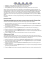
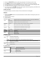
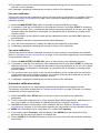
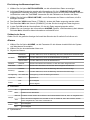
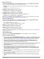
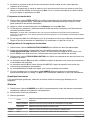
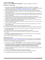
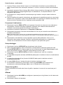
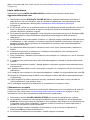
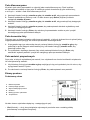
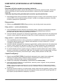
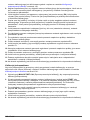
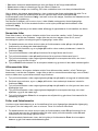
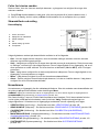
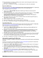
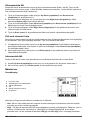
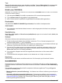
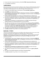
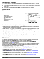
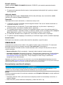
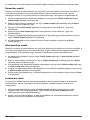
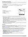
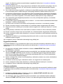
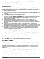
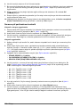
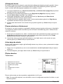
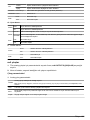
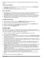
Measurement screens
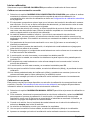
Principal display
1. Sample being measured
2. Bar graph of measurement progress
3. Current measurement graph
4. Time
5. Current measurement and unit
6. Temperature
The options at the bottom of the screen will include three of the following:
• Hist - Selecting this option will show the most recent measurements along with the last grab
sample and verification details.
• Stop - Select this option to stop the current process on the analyzer. This could be a
measurement, verification or grab sample process. The option is only available when one of these
processes is currently running. You will be asked for confirmation (YES or NO) that you want to
stop the process.
• Start - Select this option to start the analyzer measurement process. This option is only available if
the analyzer has been stopped.
• Menu - This will bring up the main menu screen.
• Alarm - This option will appear flashing on the screen if any alarms have been set. Selecting this
option will take you to the alarms screen.
Main menu
The main menu is accessible from any one of the measurement screens. To access the main menu
screen press the Up Arrow function key under the Menu option.
Note: Access to the Main Menu will require a password if a PROGRAMMING password has been set (see
Passwords on page 15).
14
English

The first option in the menu will always be highlighted by default. To scroll to the option required,
press the Up Arrow function key under the Select option. Detailed information on each of the main
menu options is available elsewhere in this manual as follows:
• VERIFICATION - See section entitled VERIFICATION on page 22
• GRAB SAMPLE - See section entitled GRAB SAMPLE on page 23
• CALIBRATION - See section entitled CALIBRATION on page 19
• MAINTENANCE/DIAG. - See section entitled MAINTENANCE/DIAG. on page 23
• USER SETUP - See section entitled USER SETUP on page 16
• SYSTEM SETUP - See section entitled SYSTEM SETUP on page 15
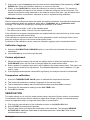
SYSTEM SETUP
Date and time
1. Select the DATE/TIME option to access the date/time sub-menu.
2. Scroll to the required day and press the Enter function key.
3. Enter the day, month, and year.
4. Enter the time in HH:MM:SS format (24 hour clock).
5. On completion press Esc to return to the main System Setup menu.
Display options
1. Select the DISPLAY option to set up the display parameters.
2. Select the LANGUAGE, CONC. UNIT and TEMPERATURE UNIT fields in turn, and set your
preferences by scrolling through the available options.
Passwords
1. Select the PASSWORDS option to set passwords for access to programming, calibration and
system setup options.
2. Each password is a 4-digit numeric field. Enter the required value for each of the three
passwords. A value of 0000 signifies no password is required to gain access to those menu
options.
Default values
1. Select the DEFAULT VALUES option to erase all the previously set user parameters and load
the default values. A warning message is displayed and confirmation of this action is required.
2. To exit from the screen without loading the default values, press the Esc function key.
3. To load the default values, select the Yes option.
Adjust mA output
1. Select the ADJUST mA OUTPUT option to access the analyzer’s analog output parameters.
2. Select the mA output you wish to change to display the next screen.
3. The option to increase or decrease the low end value (0 mA or 4 mA depending on your setting)
is displayed. Change the value up or down by selecting the Minus or Plus indicators at the
bottom of the screen.
4. On completion press the Enter function key and the display changes to 20 mA.
5. Enter the adjustment value in the same way as for the low end value. On completion press the
Enter function key, and the display reverts back to the main ADJUST mA OUTPUT screen, to
allow you to select the next output to adjust.
English
15

USER SETUP
Measurement
Targeted pH (non-cationic applications only)
Select the pH option and enter the target pH value for your application. The measured pH value of
the sample in the measuring cell should be within ±0.2 pH of the target.
Total gas/water ratio (cationic applications only)
1. For each channel, enter the ratio of gas to water to minimize the DIPA consumption. This is part
of the installation procedure and is explained in more detail in the installation section of the full
user manual.
Measure steps
1. Select the MEASURE STEPS option to set up the measurement timings.
Measure steps - single channel
1. The on line measurement time defines the measurement time of the sample and how often the
measurement values are stored in memory. For a single channel configuration, it is
recommended to leave this time at the default value of 10 minutes.
2. If smart rinsing is required after a calibration, grab sample or sensor reactivation, set this
parameter to Yes and define the maximum rinse time.
Measure steps - multi channel
1. The on line measurement time is the time when the analyzer displays the true sodium
measurement. This value must be at least 1 minute and less than the cycle time.
2. If smart rinsing is required after a calibration, grab sample or sensor reactivation, set this
parameter to Yes and define the maximum rinse time.
3. The cycle time is the total measurement time for each channel and cannot be less than
10 minutes.
4. After a change of measurement channel, for a manual mode with a fixed cycle time, set the
search stability mode to No. For an automatic mode which minimizes the cycle time, set this
parameter to Yes.
Reactivation frequency
1. Select the ACTIVAT. FREQ option to set the time period between electrode reactivation. When
this time period expires, the electrode is reactivated automatically with an injection of a small
amount of reactivation solution.
2. Set the reactivation mode to either a Frequency or a fixed date.
3. If set to frequency, the recommended time period is 24 hours so that the electrode is reactivated
on a daily basis.
Note: If this value is set to zero, then no electrode reactivation will take place during the calibration process and
as such the calibration may be inaccurate. It is highly recommended to set this parameter to 24.
4. If set to a fixed date, define the day and time of the week when reactivation takes place. Set the
day of the week to an asterisk if reactivation is not to take place on that day.
Datalogger setup
1. Select the VIEW DATA option to display the requested data.
2. All information matching the parameters selected in the VIEW SETUP option is displayed on the
screen. If the data covers more than one screen, an Arrow key will be displayed at the bottom.
Use this key to scroll through the data.
16
English

3. Select the VIEW SETUP option to define the parameters for the data you wish to view.
4. The FROM data field is the date (DD/MM/YY) from which you want to start viewing data.
5. The AT data field is the time (HH:MM:SS format) from which you want to start viewing the data.
6. The CH field defines the channel for which you want to view the data.
7. If you wish to see the ALARMS information (both system and warning alarms), select Yes in this
field, or No if alarm information is not required.
Graph time base
For graphical displays, enter the number of hours as the base line for the graph.
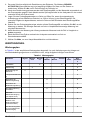
Alarms
1. Select the ALARMS option to set up the parameters for all the alarms including the system and
warning alarms.
2. Select the alarm to set up.
3. General alarms:
Mode
Limit Trigger the alarm when the measurement is above or below a pre-defined limit
Sample flow Trigger the alarm when the sample flow rate is too low
Active channel Trigger the alarm when the channel is active
Attributes Channel n Defines the channel number on which the alarm is triggered
Limit nnnn Define the limit when the alarm should be triggered
Direction
Up Trigger alarm when measurement is above the limit
Down Trigger alarm when measurement is below the limit
Delay nnn seconds The delay before the alarm is activated
Hysteresis nn% Hysteresis %
Relay
N.O. Normally open
N.C. Normally closed
4. Warning alarm:
Alarm
Yes Activate the warning alarm
No Deactivate the warning alarm
Accept
Manual When the alarm is triggered, turn it off by pressing the Enter function key
Auto
When the alarm is triggered, it will turn itself off only when the reason for the alarm being
triggered is no longer valid
Relay
N.O. Normally open
N.C. Normally closed
5. System alarm:
Alarm
Yes Activate the system alarm
No Deactivate the system alarm
Relay
N.O. Normally open
N.C. Normally closed
English 17

mA outputs
1. Select the mA OUTPUTS option to set up the parameters for all the analog outputs.
2. From the list available, select the mA output you wish to set.
Output parameters
1. Analog output parameters:
Attribute
Choose the attribute that triggers the analog output.
Note: The attribute variable cannot be applied to Output 0, which is reserved for the continuous live output signal.
Type Choose either a 0-20 mA or 4-20 mA analog output
Mode Select the mode. This parameter is only selectable if the attribute is set to a measurement channel
Low The value corresponding to the low end of the scale
Middle The value corresponding to the mid-point of the scale (only available in dual mode)
High The value corresponding to the high end of the scale
Event indication
1. Select the EVENT INDICATION option in the mA Outputs menu to display the options available
for event setting.
2. Select the option for which you want to set an event.
3. Define the attribute for the event. This is one of the outputs or None.
4. The MODE can be either a Preset val or Frozen.
5. If a preset value is chosen, you will be required to enter the value of the analog output that will be
forced, when that event occurs.
Test
This option allows you to enter a value into the mA field. Press the Enter function key to force this
value on all the analog outputs. The value can then be verified with the use of a multimeter
connected to the analyzer.
RS485 (or PROFIBUS)
Note: If the PROFIBUS option has been installed, then the menu option will show PROFIBUS rather than RS485,
and the PROFIBUS parameters will need to be installed.
1. Select the RS485 option to set up the parameters for the communications protocol.
2. Press the Enter function key to accept each data element.
3. On completion, press the Esc function key to return to the user setup screen.
18
English

Sample channels
Select the SAMPLE CHANNELS option to set up the channel parameters.
Number of channels
1. If the number of channels parameter is changed, an activation key will be required before the
additional channel is recognized.
Channel activation
Using the Up and Down Arrow keys, define whether the channel is active (Activ) or inactive
(Inactiv).
Sequence
The sequence defines the channel order in which samples are measured.
1. Only configured channels can be used in the sequence. For example for a 3-channel analyzer
only values 1,2 and 3 are available.
2. Up to 12 sequences can be defined. If a channel has been deactivated, but is still in the
sequence, it is simply ignored and the next channel in sequence is measured.
3. If there is no sample on a programmed channel, the analyzer will detect this and after 3 minutes
move on to the next channel in sequence. The channel on which the sample is missing will be
assigned the alarm sample x flow < min (where sample x is the name of the channel).
4. If the analyzer is stopped manually from the keyboard, it restarts from the same place in the
sequence.
5. In the event of a power failure, when restarted the analyzer with start at the beginning of the
sequence.
Channel names
Define the name of the channel with free-format alphanumeric text up to a maximum of 8 characters.
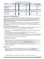
CALIBRATION
The instrument cannot be calibrated until at least one complete measurement cycle has been
successfully performed. An attempt to calibrate the instrument before this will result in a “Not
authorized” message being displayed.
In order to obtain accurate measurement results, the analyzer should be calibrated on a regular
basis. Two basic methods of calibration are available:
• Manual calibration - The user can manually perform a calibration on an ad-hoc basis.
• Automatic calibration - Parameters can be set up so that the analyzer will perform a calibration
automatically on pre-defined days at a pre-defined time (see Automatic calibration setup
on page 21). This type of calibration is always done using known calibration solution
concentrations.
Note: Before starting a calibration It is very important to ensure that the Reactivation Frequency parameter (see
Reactivation frequency on page 16) is greater than zero. If set to zero, the electrode reactivation process will not
take place during calibration and as such the measurement results may well be out of limits.
Calibration solution concentrations
N O T I C E
The maximum concentration value for any calibration solution cannot be greater than 2000 ppm. Any value
superior to this is outside the analyzer specifications and cannot be processed.
Manual calibration
For a manual calibration, the calibration solutions must be between 100 ppb and 2000 ppm and
must respect the following rules:
English
19

• LOW CAL SOL must be ≥ sample concentration of Na
+
and a minimum of 100 ppb
• HIGH CAL SOL = (LOW CAL SOL x 10)
Example 1: sample concentration of Na
+
= 20 ppb
→ LOW CAL SOL = minimum value = 100 ppb Na
+
→ HIGH CAL SOL = (100 ppb x 10) = 1000 ppb Na
+
Example 2: sample concentration of Na
+
= 450 ppb
→ LOW CAL SOL = ≥ sample concentration of Na
+
= 500 ppb Na
+
→ HIGH CAL SOL = (500 ppb x 10) = 5000 ppb Na
+
Note: The values LOW CAL SOL and HIGH CAL SOL must be entered into the system (see One point calibration
on page 21 or Two point calibration on page 21).
Automatic calibration
For an automatic calibration, the calibration solution must be between 10 ppm and 2000 ppm and
must respect the following rules:
• CAL SOL minimum = 10 ppm
• CAL SOL = (sample concentration of Na
+
x 1000)
Example 1: sample concentration of Na
+
= 0.1 ppb
→ CAL SOL = minimum value = 10 ppm Na
+
Example 2: sample concentration of Na
+
= 1 ppm
→ CAL SOL = (1 ppm x 1000) = 1000 ppm Na
+
Note: The value CAL SOL must be entered into the system (see Automatic calibration setup on page 21)
Start calibration
Select the START CALIBRATION option to calibrate the analyzer manually.
Calibrate known addition
1. Select the CAL.KNOWN ADDITION option to calibrate the analyzer by mixing the sample with a
known concentration of calibration solution. The concentration of the calibration solution is
defined in Automatic calibration setup on page 21.
2. The instrument first checks that the volume of calibration solution remaining is enough. If not, a
warning alarm is activated and the instrument returns to normal measurement with the original
parameters.
3. If the volume of solution is OK, the background point measurement (P0) to be used as the base
measurement value is taken. This is the measurement against the sample before any additions of
the calibration solution have been made.
4. The measurement must be stable and less than 1 per thousand of the calibration solution
concentration, otherwise the instrument returns to normal measurement with the original
parameters. Provided the measurement is OK, the P0 measurement details are displayed on
screen.
5. If the reactivation frequency parameter is not zero (as is highly recommended), the electrode will
be reactivated.
6. When the reactivation process is complete, the overflow vessel is rinsed to remove all traces of
sample.
7. After rinsing, the overflow vessel is re-filled with sample plus 2mL of the calibration solution.
8. The sample is then measured and the details displayed against P1.
9. When the measurement is stable, the details are displayed at the top of the screen against
measurement P1.
10. The overflow vessel is then rinsed and re-filled with sample plus 20mL of the calibration solution.
11. This sample is then measured and the details displayed against P2.
12. Once the final measurement is stable, the offset and slope for this calibration are calculated.
20
English
Seite wird geladen ...
Seite wird geladen ...
Seite wird geladen ...
Seite wird geladen ...
Seite wird geladen ...
Seite wird geladen ...
Seite wird geladen ...
Seite wird geladen ...
Seite wird geladen ...
Seite wird geladen ...
Seite wird geladen ...
Seite wird geladen ...
Seite wird geladen ...
Seite wird geladen ...
Seite wird geladen ...
Seite wird geladen ...
Seite wird geladen ...
Seite wird geladen ...
Seite wird geladen ...
Seite wird geladen ...
Seite wird geladen ...
Seite wird geladen ...
Seite wird geladen ...
Seite wird geladen ...
Seite wird geladen ...
Seite wird geladen ...
Seite wird geladen ...
Seite wird geladen ...
Seite wird geladen ...
Seite wird geladen ...
Seite wird geladen ...
Seite wird geladen ...
Seite wird geladen ...
Seite wird geladen ...
Seite wird geladen ...
Seite wird geladen ...
Seite wird geladen ...
Seite wird geladen ...
Seite wird geladen ...
Seite wird geladen ...
Seite wird geladen ...
Seite wird geladen ...
Seite wird geladen ...
Seite wird geladen ...
Seite wird geladen ...
Seite wird geladen ...
Seite wird geladen ...
Seite wird geladen ...
Seite wird geladen ...
Seite wird geladen ...
Seite wird geladen ...
Seite wird geladen ...
Seite wird geladen ...
Seite wird geladen ...
Seite wird geladen ...
Seite wird geladen ...
Seite wird geladen ...
Seite wird geladen ...
Seite wird geladen ...
Seite wird geladen ...
Seite wird geladen ...
Seite wird geladen ...
Seite wird geladen ...
Seite wird geladen ...
Seite wird geladen ...
Seite wird geladen ...
Seite wird geladen ...
Seite wird geladen ...
Seite wird geladen ...
Seite wird geladen ...
Seite wird geladen ...
Seite wird geladen ...
Seite wird geladen ...
Seite wird geladen ...
Seite wird geladen ...
Seite wird geladen ...
Seite wird geladen ...
Seite wird geladen ...
Seite wird geladen ...
Seite wird geladen ...
Seite wird geladen ...
Seite wird geladen ...
Seite wird geladen ...
Seite wird geladen ...
Seite wird geladen ...
Seite wird geladen ...
Seite wird geladen ...
Seite wird geladen ...
Seite wird geladen ...
Seite wird geladen ...
Seite wird geladen ...
Seite wird geladen ...
Seite wird geladen ...
Seite wird geladen ...
Seite wird geladen ...
Seite wird geladen ...
Seite wird geladen ...
Seite wird geladen ...
Seite wird geladen ...
Seite wird geladen ...
Seite wird geladen ...
Seite wird geladen ...
Seite wird geladen ...
Seite wird geladen ...
Seite wird geladen ...
Seite wird geladen ...
Seite wird geladen ...
Seite wird geladen ...
Seite wird geladen ...
Seite wird geladen ...
Seite wird geladen ...
Seite wird geladen ...
Seite wird geladen ...
Seite wird geladen ...
Seite wird geladen ...
Seite wird geladen ...
Seite wird geladen ...
Seite wird geladen ...
Seite wird geladen ...
Seite wird geladen ...
Seite wird geladen ...
Seite wird geladen ...
Seite wird geladen ...
Seite wird geladen ...
Seite wird geladen ...
Seite wird geladen ...
Seite wird geladen ...
Seite wird geladen ...
Seite wird geladen ...
Seite wird geladen ...
Seite wird geladen ...
Seite wird geladen ...
Seite wird geladen ...
Seite wird geladen ...
Seite wird geladen ...
Seite wird geladen ...
Seite wird geladen ...
Seite wird geladen ...
Seite wird geladen ...
Seite wird geladen ...
Seite wird geladen ...
Seite wird geladen ...
Seite wird geladen ...
Seite wird geladen ...
Seite wird geladen ...
Seite wird geladen ...
Seite wird geladen ...
Seite wird geladen ...
Seite wird geladen ...
Seite wird geladen ...
Seite wird geladen ...
Seite wird geladen ...
Seite wird geladen ...
Seite wird geladen ...
Seite wird geladen ...
Seite wird geladen ...
Seite wird geladen ...
Seite wird geladen ...
Seite wird geladen ...
Seite wird geladen ...
Seite wird geladen ...
Seite wird geladen ...
Seite wird geladen ...
Seite wird geladen ...
Seite wird geladen ...
Seite wird geladen ...
Seite wird geladen ...
Seite wird geladen ...
Seite wird geladen ...
Seite wird geladen ...
Seite wird geladen ...
Seite wird geladen ...
Seite wird geladen ...
Seite wird geladen ...
Seite wird geladen ...
Seite wird geladen ...
Seite wird geladen ...
Seite wird geladen ...
Seite wird geladen ...
Seite wird geladen ...
Seite wird geladen ...
Seite wird geladen ...
Seite wird geladen ...
Seite wird geladen ...
Seite wird geladen ...
Seite wird geladen ...
Seite wird geladen ...
Seite wird geladen ...
Seite wird geladen ...
Seite wird geladen ...
Seite wird geladen ...
Seite wird geladen ...
Seite wird geladen ...
Seite wird geladen ...
Seite wird geladen ...
Seite wird geladen ...
Seite wird geladen ...
Seite wird geladen ...
Seite wird geladen ...
Seite wird geladen ...
Seite wird geladen ...
Seite wird geladen ...
Seite wird geladen ...
Seite wird geladen ...
Seite wird geladen ...
Seite wird geladen ...
Seite wird geladen ...
Seite wird geladen ...
Seite wird geladen ...
Seite wird geladen ...
Seite wird geladen ...
Seite wird geladen ...
Seite wird geladen ...
Seite wird geladen ...
Seite wird geladen ...
Seite wird geladen ...
Seite wird geladen ...
Seite wird geladen ...
Seite wird geladen ...
Seite wird geladen ...
Seite wird geladen ...
Seite wird geladen ...
Seite wird geladen ...
Seite wird geladen ...
Seite wird geladen ...
Seite wird geladen ...
Seite wird geladen ...
Seite wird geladen ...
Seite wird geladen ...
Seite wird geladen ...
Seite wird geladen ...
Seite wird geladen ...
Seite wird geladen ...
Seite wird geladen ...
Seite wird geladen ...
Seite wird geladen ...
Seite wird geladen ...
Seite wird geladen ...
Seite wird geladen ...
Seite wird geladen ...
Seite wird geladen ...
Seite wird geladen ...
Seite wird geladen ...
Seite wird geladen ...
Seite wird geladen ...
Seite wird geladen ...
Seite wird geladen ...
Seite wird geladen ...
Seite wird geladen ...
Seite wird geladen ...
Seite wird geladen ...
Seite wird geladen ...
Seite wird geladen ...
Seite wird geladen ...
Seite wird geladen ...
Seite wird geladen ...
Seite wird geladen ...
Seite wird geladen ...
Seite wird geladen ...
Seite wird geladen ...
Seite wird geladen ...
Seite wird geladen ...
Seite wird geladen ...
Seite wird geladen ...
Seite wird geladen ...
Seite wird geladen ...
Seite wird geladen ...
Seite wird geladen ...
Seite wird geladen ...
Seite wird geladen ...
Seite wird geladen ...
Seite wird geladen ...
Seite wird geladen ...
Seite wird geladen ...
-
 1
1
-
 2
2
-
 3
3
-
 4
4
-
 5
5
-
 6
6
-
 7
7
-
 8
8
-
 9
9
-
 10
10
-
 11
11
-
 12
12
-
 13
13
-
 14
14
-
 15
15
-
 16
16
-
 17
17
-
 18
18
-
 19
19
-
 20
20
-
 21
21
-
 22
22
-
 23
23
-
 24
24
-
 25
25
-
 26
26
-
 27
27
-
 28
28
-
 29
29
-
 30
30
-
 31
31
-
 32
32
-
 33
33
-
 34
34
-
 35
35
-
 36
36
-
 37
37
-
 38
38
-
 39
39
-
 40
40
-
 41
41
-
 42
42
-
 43
43
-
 44
44
-
 45
45
-
 46
46
-
 47
47
-
 48
48
-
 49
49
-
 50
50
-
 51
51
-
 52
52
-
 53
53
-
 54
54
-
 55
55
-
 56
56
-
 57
57
-
 58
58
-
 59
59
-
 60
60
-
 61
61
-
 62
62
-
 63
63
-
 64
64
-
 65
65
-
 66
66
-
 67
67
-
 68
68
-
 69
69
-
 70
70
-
 71
71
-
 72
72
-
 73
73
-
 74
74
-
 75
75
-
 76
76
-
 77
77
-
 78
78
-
 79
79
-
 80
80
-
 81
81
-
 82
82
-
 83
83
-
 84
84
-
 85
85
-
 86
86
-
 87
87
-
 88
88
-
 89
89
-
 90
90
-
 91
91
-
 92
92
-
 93
93
-
 94
94
-
 95
95
-
 96
96
-
 97
97
-
 98
98
-
 99
99
-
 100
100
-
 101
101
-
 102
102
-
 103
103
-
 104
104
-
 105
105
-
 106
106
-
 107
107
-
 108
108
-
 109
109
-
 110
110
-
 111
111
-
 112
112
-
 113
113
-
 114
114
-
 115
115
-
 116
116
-
 117
117
-
 118
118
-
 119
119
-
 120
120
-
 121
121
-
 122
122
-
 123
123
-
 124
124
-
 125
125
-
 126
126
-
 127
127
-
 128
128
-
 129
129
-
 130
130
-
 131
131
-
 132
132
-
 133
133
-
 134
134
-
 135
135
-
 136
136
-
 137
137
-
 138
138
-
 139
139
-
 140
140
-
 141
141
-
 142
142
-
 143
143
-
 144
144
-
 145
145
-
 146
146
-
 147
147
-
 148
148
-
 149
149
-
 150
150
-
 151
151
-
 152
152
-
 153
153
-
 154
154
-
 155
155
-
 156
156
-
 157
157
-
 158
158
-
 159
159
-
 160
160
-
 161
161
-
 162
162
-
 163
163
-
 164
164
-
 165
165
-
 166
166
-
 167
167
-
 168
168
-
 169
169
-
 170
170
-
 171
171
-
 172
172
-
 173
173
-
 174
174
-
 175
175
-
 176
176
-
 177
177
-
 178
178
-
 179
179
-
 180
180
-
 181
181
-
 182
182
-
 183
183
-
 184
184
-
 185
185
-
 186
186
-
 187
187
-
 188
188
-
 189
189
-
 190
190
-
 191
191
-
 192
192
-
 193
193
-
 194
194
-
 195
195
-
 196
196
-
 197
197
-
 198
198
-
 199
199
-
 200
200
-
 201
201
-
 202
202
-
 203
203
-
 204
204
-
 205
205
-
 206
206
-
 207
207
-
 208
208
-
 209
209
-
 210
210
-
 211
211
-
 212
212
-
 213
213
-
 214
214
-
 215
215
-
 216
216
-
 217
217
-
 218
218
-
 219
219
-
 220
220
-
 221
221
-
 222
222
-
 223
223
-
 224
224
-
 225
225
-
 226
226
-
 227
227
-
 228
228
-
 229
229
-
 230
230
-
 231
231
-
 232
232
-
 233
233
-
 234
234
-
 235
235
-
 236
236
-
 237
237
-
 238
238
-
 239
239
-
 240
240
-
 241
241
-
 242
242
-
 243
243
-
 244
244
-
 245
245
-
 246
246
-
 247
247
-
 248
248
-
 249
249
-
 250
250
-
 251
251
-
 252
252
-
 253
253
-
 254
254
-
 255
255
-
 256
256
-
 257
257
-
 258
258
-
 259
259
-
 260
260
-
 261
261
-
 262
262
-
 263
263
-
 264
264
-
 265
265
-
 266
266
-
 267
267
-
 268
268
-
 269
269
-
 270
270
-
 271
271
-
 272
272
-
 273
273
-
 274
274
-
 275
275
-
 276
276
-
 277
277
-
 278
278
-
 279
279
-
 280
280
-
 281
281
-
 282
282
-
 283
283
-
 284
284
-
 285
285
-
 286
286
-
 287
287
-
 288
288
-
 289
289
-
 290
290
-
 291
291
-
 292
292
-
 293
293
-
 294
294


in anderen Sprachen
- English: Hach polymetron 9240
- français: Hach polymetron 9240
- español: Hach polymetron 9240
- italiano: Hach polymetron 9240
- dansk: Hach polymetron 9240
- polski: Hach polymetron 9240
- svenska: Hach polymetron 9240
- Türkçe: Hach polymetron 9240
Verwandte Artikel
-
 Hach POLYMETRON 9245 Basic User Manual
-
 Hach NA5600 sc Na+ Operations
-
 Hach ORBISPHERE K1200 Basic User Manual
-
 Hach ORBISPHERE K-M1100 Basic User Manual
-
 Hach 9586sc Basic User Manual
-
 Hach NA5600 sc Na+ Maintenance And Troubleshooting Manual
-
 Hach PHOSPHAX indoor sc Addendum
-
 Hach 51 Series Benutzerhandbuch
-
 Hach ORBISPHERE 3650 Atex Basic User Manual
-
 Hach Polymetron 9611sc PO43-LR Bedienungsanleitung


