SICK MultiPac Sensor WTB27-3 RT DC Bedienungsanleitung
- Typ
- Bedienungsanleitung

A
Subject to change without notice
Irrtümer und Änderungen vorbehalten
Sujet à modication sans préavis
Alterações poderão ser feitas sem prévio aviso
Med forbehold for ændringer og fejl
Contenuti soggetti a modiche senza preavviso
Wijzigingen en correcties voorbehouden
Sujeto a cambio sin previo aviso
如有更改,不另行通知
------------------------------------------------------------- 8014204.Y532 0314 CV ---------------------------------------------------------
MultiPac Sensor
WTB27-3 RT DC
DEUTSCH
Reexions-Lichttaster
mit sichtbarem Rotlicht
Betriebsanleitung
Sicherheitshinweise
> Vor der Inbetriebnahme die Betriebsanleitung lesen.
> Anschluss, Montage und Einstellung nur durch Fachpersonal.
> Gerät bei Inbetriebnahme vor Feuchte und Verunreinigung schützen.
> Kein Sicherheitsbauteil gemäß EU-Maschinenrichtlinie. Nur zur
Verwendung in Anwendungen gemäß NFPA 79. Von UL gelistete
Adapter mit Anschlusskabeln sind verfügbar. Enclosure type 1.
Bestimmungsgemäße Verwendung
Der Reexions-Lichttaster WTB27-3 RT ist ein optoelektronischer Sensor
und wird zum optischen, berührungslosen Erfassen von Sachen, Tieren und
Personen eingesetzt.
Inbetriebnahme
1 Die Geräte WTB27-3 haben antivalente Schaltausgänge:
Nur WTB27-3P (PNP, Last → M):
Q: dunkelschaltend, Objekt wird nicht erkannt, Ausgang HIGH,
Q: hellschaltend, Objekt wird erkannt, Ausgang HIGH.
Nur WTB27-3N (NPN, Last → L+):
Q: dunkelschaltend, Objekt wird nicht erkannt, Ausgang LOW,
Q: hellschaltend, Objekt wird erkannt, Ausgang LOW.
Gewünschte Betriebsart gemäß B anschließen.
2 Nur bei den Steckerversionen:
Leitungsdose spannungsfrei aufstecken und festschrauben.
3 Sensor an geeignete Halter anschrauben (z.B. SICK-Haltewinkel).
Lichttaster an Betriebsspannung legen (s. Typenaufdruck). Grüne LED
leuchtet.
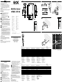
4 Einsatzbedingungen wie Tastweite, Objektgröße und Remissionsver-
mögen des Tastgutes sowie des Hintergrundes überprüfen und mit der
Kennlinie im Diagramm vergleichen. (x = Tastweite, y = Übergangsbe-
reich zwischen eingestellter Tastweite und sicherer Hintergrundaus-
blendung (z) in % der Tastweite, Ro = Remission Objekt, Rh =
Remission Hintergrund). Remission: 6 % = schwarz, 18 % = grau, 90 %
= weiß (bezogen auf Standardweiß nach DIN 5033).
5 Ausrichtung des Sensors auf das Objekt: Objekt positionieren.
Lichteck auf Objekt ausrichten.
6 Tastweiteneinstellung mit Doppel-Teach-Taste:
-3P_ _ _3, -3N_ _ _3
Gleichzeitig „+“/„–“-Tasten drücken (ca. 2 s), bis gelbe Empfangsan-
zeige blinkt: Objekt wird erfasst. Bei Tastenbetätigung < 2 s erfolgt kein
Teach-in = Manipulationsschutz. Tasten loslassen, gelbe Empfangsan-
zeige leuchtet konstant: Objekt wird sicher erkannt.
Bei Bedarf Feinkorrektur des Tastabstandes zur Anpassung an die
Applikationsbedingungen:
„+“-Taste drücken (ca. 0,5 s): Tastabstand wird erhöht.
„–“-Taste drücken (ca. 0,5 s): Tastabstand wird verringert. Bei der
Tastenbetätigung < 0,5 s erfolgt keine Korrektur = Manipulations-
schutz. Pro Tastendruck blinkt die gelbe Empfangsanzeige 1x auf.
Eingestellte Tastweite wird gespeichert. Leuchtet die gelbe Empfang-
sanzeige nicht, Lichttaster neu justieren, reinigen bzw. Einsatzbedin-
gungen überprüfen und Teach-in-Vorgang wiederholen.
Applikationsspezische Hinweise
Unter www.sick.com sind applikationspezische Hinweise verfügbar.
Vollständige Gerätebezeichnung oder Artikelnummer in Suchmaske von
www.sick.com eingeben. Auf der Produktinformationsseite können unter
„Dokumentation” die applikationsspezischen Hinweise abgerufen werden.
Wartung
SICK-Lichttaster sind wartungsfrei.
Wir empfehlen, in regelmäßigen Abständen
- die optischen Grenzächen zu reinigen,
- Verschraubungen und Steckverbindungen zu überprüfen.
24.6 (0.97)
5.2
(0.2)
54.8 (2.16)
70 (2.76)
80.6 (3.17)
40 (1.57)
50 (1.97)
12.2
(0.48)
39 (1.54)
23 (0.91)
8.4 (0.33)
18
(0.71)
18
(0.71)
WTB27-3
4
TEACH
+–
+
–
3
5
1 2
(PNP)
(NPN)
Q
1
0
1
0
Q
ENGLISH
Photoelectric Proximity Sensor
with visible red light
Operating Instructions
Safety Specications
> Read the operating instructions before starting operation.
> Connection, assembly, and settings only by competent technicians.
> Protect the device against moisture and soiling when operating.
> No safety component in accordance with EU machine guidelines.
For use in NFPA 79 applications only. UL-listed adapters providing
eld wiring leads are available. Enclosure type 1.
Proper Use
The WTB27-3 RT photoelectric proximity sensor is an opto-electronic sensor
and is used for detection of optical, non-contact detection of objects,
animals, and people.
Starting Operation
1 The devices WTB27-3 have antivalent switching outputs:
Only WTB27-3P (PNP, load → M):
Q: dark-switching, Object is not detected, output HIGH,
Q: light-switching, Object is detected, output HIGH.
Only WTB27-3N (NPN, load → L+):
Q: dark-switching, Object is not detected, output LOW,
Q: light-switching, Object is detected, output LOW.
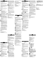
Connected desired operating mode in accordance with B .
2 With following connectors only:
Connect and secure cable receptacle tension-free.
3 Screw on sensor to appropriate bracket (e.g., SICK mounting bracket).
Maintain direction in which object moves relative to sensor. Connect
photoelectric proximity switch to operating voltage (see type label).
Green LED lights.
4 Check application conditions such as sensing distance, size and
reectance of object to be detected as well as of background, and
compare with characteristic in diagram. (x = sensing distance, y =
transition range between set sensing distance and reliable back-
ground suppression (z) in % of sensing distance, Ro = reectance of
object, Rh = reectance of background). Reectance: 6 % = black,
18 % = gray, 90 % = white (based on standard white to DIN 5033).
5 Alignment of sensor to the object: Position object. Position light spot
on object.
6 Sensing range setting with double-teach key:
-3P_ _ _3, -3N_ _ _3
Press the “+”/“–” keys at the same time (approx. 2 s) until the yellow
signal strength indicator blinks. Object is detected. There is no teach-
in if the keys are pressed < 2 s = manipulation protection. Release the
keys; the yellow signal strength indicator lights continuously. Object is
detected reliably. If required, correct the sensing distance precisely for
adaptation to the application conditions.
Press “+” button (approx. 0.5 s): sensing distance is increased. Press
“– ” button (approx. 0.5 s): sensing distance is decreased. There is no
correction if the keys are pressed < 0.5 s = manipulation protection.
The yellow signal strength indicator lights 1x each time you press the
keys. Set sensing range is stored. If the yellow signal strength indicator
does not light, readjust the photoelectric proximity switch, clean it
and/or check the application conditions and then repeat the teach-in
procedure.
Application-specic notes
Application-specic notes are available under www.sick.com. Enter
the complete device designation or part number in the search box at
www.sick.com. The application-specic notes can be called up on the
product information page under “Literature”.
Maintenance
SICK photoelectric sensor do not require any maintenance. We recommend
that you clean the external lens surfaces and check the screw connections
and plug-in connections at regular intervals.
L+
Q
Q
M
brn
blk
wht
blu
1
4
2
3
P2483
N2483
0
0
9
8
7
6
5
4
3
2
1
10
100
(3.94)
200
(7.87)
300
(11.81)
400
(15.75)
500
(19.69
)
6%/90%
18%/90%
90%/90%
% of sensing distance
Distance in mm (inch)
6
TEACH
+–
+
–
P2483
N2483
B
WTB27-3 P2483
N2483
Sensing distance TW
1)
, max. Tastweite TW
1)
, max. Distance de détectoion TW
1)
, max. Portata di ricezione TW
1)
, max. Impulslengte TW
1)
, max. 30 ... 500 mm
Operating distance, adjustable
1)
Betriebstastweite, einstellbar
1)
Distance de détection, réglable
1)
Raio de exploração, ajusável
1)
tastafstand, regelbaar
1)
100 ... 500 mm
Light spot diameter/distance Lichtfleckdurchmesser/Entfernung Diamètre de la tache lumineuse/Distance Diâmetro do ponto de luz/distância Lyspletdiameter/afstand ~ 12 mm/500 mm
Supply voltage V
S
Versorgungsspannung U
V
Tension d'alimentation U
V
Tensão de força U
V
Forsyningsspænding U
V
10 ... 30 V DC
2)
Output current I
max
Ausgangsstrom I
max.
Courant de sortie I
maxi
Corrente de saída I
máx
. Udgangsstrøm I
max.
100 mA
Switching frequency
3)
Schaltfolge
3)
Fréquence
3)
Sequência min. de sinais
3)
Signalfølge min.
3)
100/s
Response time
4)
Ansprechzeit
4)
Temps de réponse
4)
Tempo de reação
4)
Responstid
4)
5 ms
Enclosure rating (IEC 60529) Schutzart (IEC 60529) Type de protection (IEC 60529) Tipo de proteção (IEC 60529) Tæthedsgrad (IEC 60529) IP 66, IP 67
Protection class Schutzklasse Classe de protection Classe de proteção Beskyttelsesklasse
5)
Circuit protection
6)
Schutzschaltungen
6)
Circuits de protection
6)
Circuitos protetores
6)
Beskyttelseskoblinger
6)
A, B, C
Ambient operating temperature Betriebsumgebungstemperatur Température ambiante Temperatura ambiente de operação Driftsomgivelsestemperatur –30 ... +60 °C
1)
Object 90 % reflection
according to DIN 5033
2)
Limits; Operation in short-circuit
2)
protected network max. 8 A;
Residual ripple max. 5 V
PP
3)
With light/dark ratio 1:1
4)
Signal transit time with resistive load
5)
Reference voltage 50 V DC
6)
A = V
S
connections reverse
polarity protected
B = outputs protected against
short circuits
C = interference pulse suppression
1)
Objekt 90 % Remission
nach DIN 5033
2)
Grenzwerte; Betrieb im kurzschluss-
geschützten Netz max. 8 A;
Restwelligkeit max. 5 V
SS
3)
Bei Hell/Dunkelverhältnis 1:1
4)
Signallaufzeit bei ohmscher Last
5)
Bemessungsspannung 50 V DC
6)
A = U
V
-Anschlüsse verpolsicher
B = Ausgänge kurzschlussfest
C = Störimpulsunterdrückung
1)
Objet Luminance de 90 % selon DIN 5033
2)
Valeurs limites; Service dans un
réseau protégé contre les courts-
circuits 8 A au maximum;
Ondulation résiduelle max. 5 V
SS
3)
Pour un rapport clair/sombre 1:1
4)
Durée du signal en charge ohmique
5)
Tension de calcul 50 V DC
6)
A = Raccordements U
V
protégés
contre les inversions de polarité
B = Sorties protégées contre
les courts-circuits
C = Suppression des impulsions parasites
1)
Objeto: 90 % de remissão
segundo DIN 5033
2)
Valores limite; Operação em rede
protegida contra curto-circuitos
máx. 8 A; Ondulação residual max. 5 V
SS
3)
Com uma relação luminoso/escuro de 1:1
4)
Tempo de transição do sinal com
carga ôhmica
5)
Tensão de dimensionamento 50 V DC
6)
A = Conexões U
V
protegidas
contra inversão de polos
B = Saídas protegidas contra curto circuito
C = Supressão de impulsos parasitas
1)
Objekt 90 % remission
iht. DIN 5033
2)
Grænseværdier; Drift i
kortslutningsbeskyttet net max. 8 A;
Resterende bølgethed max. 5 V
SS
3)
Ved lys-/mørkeforhold 1:1
4)
Signalløbetid ved ohmsk last
5)
Dimensioneringsspænding 50 V DC
6)
A = U
V
-tilslutninger med
polbeskyttelse
B = Udgange kortslutningsresistent
C = Støjimpulsundertrykkelse
WTB27-3 P2483
N2483
Portata di ricezione TW
1)
, max. Impulslengte TW
1)
, max. Margen de palpado TW
1)
, máx.
检测距离 TW
1)
最大值
30 ... 500 mm
Distanza di ricezione, registrabile
1)
Tastevidde
1)
Margen de palpado en servicio, ajustable
1)
工作距离,可调节
2)
100 ... 500 mm
Diametro punto luminoso/distanza Lichtvlekdiameter/Bereik Diámetro del punto luminoso/distancia
光点直径 / 距离
~ 12 mm/500 mm
Tensione di alimentazione U
V
Voedingsspanning U
V
Tensión de alimentación U
V
电源电压 U
V
10 ... 30 V DC
2)
Corrente di uscita max. I
max
. Uitgangsstroom I
max
. Corriente de salida I
máx.
输出电流 I
max
100 mA
Sequenza signali min.
3)
Signalenreeks min.
3)
Secuencia de conmutación
3)
开关频率
100/s
Tempo di risposta
4)
Aanspreektijd
4)
Tiempo de respuesta
4)
响应时间
5 ms
Tipo di protezione (IEC 60529) Beveiligingswijze (IEC 60529) Tipo de protección (IEC 60529)
防护等级(IEC 60529)
IP 66, IP 67
Classe di protezione Beveiligingsklasse Clase de protección
外壳防护等级
5)
Commutazioni di protezione
6)
Beveiligingsschakelingen
6)
Circuitos de protección
6)
电路保护
A, B, C
Temperatura ambiente circostante Bedrijfsomgevingstemperatuur Temperatura ambiente de servicio
工作环境温度
–30 ... +60 °C
1)
Oggetto 90 % remissione sec. DIN 5033
2
)
Valori limite
Funzionamento in rete con pro-
tezione dai cortocircuiti max. 8 A
ondulazione residua max. 5 V
SS
3)
Con relatio chiaro/scuro 1:1
4)
Tempo di continuare de segnale a
resistenza ohmica
5)
Tensione di taratura 50 V DC
6)
A = U
V
-collegamenti con protezione
contro inversione di poli
B = uscite a prova
di corto circuito
C = soppressione impulsi
1)
Object 90 % reflectie volgens DIN 5033
2)
Grenswaarden
Bedrijf in het kortsluiting-
beveiligdenet max. 8 A
rimpel max. 5 V
SS
3)
Bij licht-/donker-verhouding 1:1
4)
Signaaltijd bij ohmse last
5)
Meetspanning 50 V DC
6)
A = U
V
-aansluitingen beveiligd
tegen verkeerd polen
B = uitgangen beveiligd
tegen kortsluitingt
C = storingsimpulsonderdrukking
1)
Objeto con 90 % de remisión
según DIN 5033
2)
Valores límite; funcionamiento en red
protegida contra cortocircuito máx. 8 A;
ondulación residual máx. 5 V
SS
3)
Con una relación claro/oscuro de 1:1
4)
Duración de la señal con carga óhmica
5)
Tensión de medición 50 V CC
6)
A = conexiones U
V
con protección contra
polarización inversa
B = salidas a prueba de cortocircuitos
C = supresión de impulsos parásitos
1)
对表面反射率为90 %物体(基于DIN 5033
)
2)
限定值,在短路保护下电源极性反接,电流
最大为8A,纹波电压最大为5V
PP
3)
亮 / 暗比 1:1
4)
电阻性负载时,传感器检测到变化时输出信
号的转换时间
5)
额定电压 DC 50 V
6)
A = V
S
极性反接保护
B = 输出短路保护
C = 抑制脉冲干扰
Australia
Phone +61 3 9457 0600
Belgium/Luxembourg
Phone +32 (0)2 466 55 66
Brasil
Phone +55 11 3215-4900
Canada
Phone +1 905 771 14 44
Česká republika
Phone +420 2 57 91 18 50
China
Phone +86 4000 121 000
+852-2153 6300
Danmark
Phone +45 45 82 64 00
Deutschland
Phone +49 211 5301-301
España
Phone +34 93 480 31 00
France
Phone +33 1 64 62 35 00
Great Britain
Phone +44 (0)1727 831121
India
Phone +91–22–4033 8333
Israel
Phone +972-4-6801000
Italia
Phone +39 02 27 43 41
Japan
Phone +81 (0)3 3358 1341
Magyarország
Phone +36 1 371 2680
Nederland
Phone +31 (0)30 229 25 44
Österreich
Phone +43 (0)22 36 62 28 8-0
Norge
Phone +47 67 81 50 00
Polska
Phone +48 22 837 40 50
România
Phone +40 356 171 120
Russia
Phone +7-495-775-05-30
Schweiz
Phone +41 41 619 29 39
Singapore
Phone +65 6744 3732
Slovenija
Phone +386 (0)1-47 69 990
South Africa
Phone +27 11 472 3733
South Korea
Phone +82 2 786 6321/4
Suomi
Phone +358-9-25 15 800
Sverige
Phone +46 10 110 10 00
Taiwan
Phone +886-2-2375-6288
Türkiye
Phone +90 (216) 528 50 00
United Arab Emirates
Phone +971 (0) 4 8865 878
USA/México
Phone +1(952) 941-6780
BZ int42
Please find detailed addresses and additional representatives and agencies in
all major industrial nations at www.sick.com
SICK AG, Erwin-Sick-Strasse 1, D-79183 Waldkirch
Seite wird geladen ...
-
 1
1
-
 2
2


SICK MultiPac Sensor WTB27-3 RT DC Bedienungsanleitung
- Typ
- Bedienungsanleitung
in anderen Sprachen
- English: SICK MultiPac Sensor WTB27-3 RT DC Operating instructions
- français: SICK MultiPac Sensor WTB27-3 RT DC Mode d'emploi
- español: SICK MultiPac Sensor WTB27-3 RT DC Instrucciones de operación
- italiano: SICK MultiPac Sensor WTB27-3 RT DC Istruzioni per l'uso
- Nederlands: SICK MultiPac Sensor WTB27-3 RT DC Handleiding
- português: SICK MultiPac Sensor WTB27-3 RT DC Instruções de operação
- dansk: SICK MultiPac Sensor WTB27-3 RT DC Betjeningsvejledning
Verwandte Artikel
-
SICK BA WTB11-2 WTF11-2 Bedienungsanleitung
-
-
-
-
-
SICK WTB27-3P1111S07 Bedienungsanleitung
-
-
-
-
SICK WTB27-3P1161S23 Bedienungsanleitung
