
OPERATING INSTRUCTIONS / BEDIENUNGSANLEITUNG
- ENGLISH
- DEUTSCH
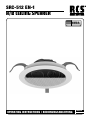
SRC-512 EN-1
A/B CEILING SPEAKER
MADE IN
GERMANY

SRC-512 EN-1
2
DESCRIPTION
This ceiling speaker is equipped with 2 loudspeakers as well
as with 2 transformers. This cabinet speaker enables space
saving A/B division and wiring of the required alarming lou
-
dspeakers through IEC 60849.
Another advantage regarding the usual A/B wiring (2 built-in
speakers) is the very low gauge level regarding the accor
-
ding range, because in case of a line failure no under served
range will occur.
Of course this has a positive impact on speaking compre
-
hensiveness and therefore on the efficiency and safety of
alarming signals.
Please consider the following features:
• Redundant dimensioning in a high-quality and moun
-
tingfriendly cabinet.
• 2 pieces high-power 4˝ oval wide band chassis and 2
high-quality transmitters enable a secure A/B wiring.
• The speaker has an installation depth of about 70 mm
and is ready for a horizontal or vertical attachment of the
speakers.
• It is available on all RAL colours on request.
BESCHREIBUNG
Dieser Einbaulautsprecher ist sowohl mit 2 Lautsprechern
wie auch mit 2 Übertragern bestückt und erlaubt damit auf
platzsparende und elegante Weise eine A/B Aufteilung und
Verkabelung der geforderten Alarmierungs-Lautsprecher
nach DIN EN 60849/VDE 0828 und VDE 0833-4.
Ein weiterer Vorteil gegenüber der üblichen Verkabelung (2
Einbaulautsprecher) ist der geringere Pegelverlust in dem
entsprechenden Bereich, weil im Falle eines Leitungsaus
-
falls kein unterversorgter Bereich entsteht.
Dies hat einen positiven Einfluss auf die Sprachverständlich
-
keit und somit auf die Effizienz und Sicherheit der alarmie-
renden Signale.
Bitte beachten Sie die folgenden Merkmale:
• Redundante Auslegung in einem hochwertigen und
montagefreundlichen Gehäuse.
• 2 Stück leistungsstarke 4˝x2,5˝-Oval-Breitbandchassis
mit Hochtonkegel und 2 hochwertige Übertrager ermög
-
lichen eine sichere A/B Verkabelung.
• Dieser Lautsprecher hat eine Einbautiefe von ca. 110mm
und eignet sich zur horizontalen wie auch vertikalen
Wand- und Deckenmontage.
• Dieser Lautsprecher ist auf Anfrage in allen RAL Farben
erhältlich.
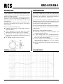
FREQUENCY RESPONSE FREQUENZBEREICH

SRC-512 EN-1
3
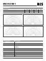
Polar Response
Polar Plots [Hz] 500 1000 2000 4000
Polar response horizontal (red) (-6dB) 162° 180° 106° 60°
Polar response vertical (blue) (-6dB) 176° 180° 172° 132°
Technichal Data SRC-512 EN-1
Input 100 V
Nominal power 2 x 6W, 3W, 1,5W
SPLP max 1 m 88dB
Nominal impedance 1.7kΩ @ 6W
3.3kΩ @ 3W
6.7kΩ @ 1,5W
Mechanical dimensions Ø 222 mm x 60 mm
Weight 1.25 kg
Sensitivity 1W/1m (100Hz - 10000Hz) 76 dB
Frequency range (-3dB) 228 - 16480 Hz
Material ABS (EN 60695-11-10 Class 5VB)
Mounting hole Ø 195 mm
Color white

SRC-512 EN-1
4

SRC-512 EN-1
5
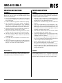
MOUNTING INSTRUCTIONS
ASSEMBLY
The necessary hole cut for the installation should have a
diameter of 195 mm ±3mm. The installation depth should
amount to at least 70 mm.
1. Remove the loudspeaker from the bayonet mounted ring
by turning the loudspeaker counterclock wise against
the mounting ring.
2. Hold the installation ring (A) with a hand into the opening.
3. Put successively the 3 tension springs „Soft-Mount-
Clips“ (B) into the designated slots of the installation
ring. This can be done very simple by taking the mount
clip between thumb and index finger of the other hand.
4. Open the touch fastener of the loudspeaker, feed the ca
-
ble through the boots and connect the cables.
5. Bring the clamps back into the bag and close the touch
fastener. Take care to close the touch fastener reliable!
6. Take care to lay the cables in a way you see in the pic
-
ture. These guarantees that no water can flow into the
loudspeaker area.
7. If one cable entry is not required, close it with the enclo
-
sed buckler.
8. After you attached the speaker part, accordingly put the
speaker (C) into the installation ring and fix the bayonet
fixing by easy rotation in clockwise direction.
DISASSEMBLY
To disassemble the speaker, go like described above in re-
verse order. The tension springs can be unmounted by unlo-
cking clips by using a small slotted screwdriver.
MONTAGEANLEITUNG
EINBAU
Der benötigte Lochausschnitt für die Installation sollte einen
Durchmesser von 195 mm ±3 mm aufweisen. Die Einbautie
-
fe sollte mindesten 70 mm betragen.
1. Entfernen Sie den Lautsprecher von dem Bajonett-Ver
-
schlussring, indem Sie den Lautsprecher entgegen dem
Uhrzeigersinn aus dem Montagering drehen.
2. Halten Sie den Installationsring (A) mit einer Hand in die
Öffnung.
3. Legen Sie nacheinander die drei Spannfedern „Soft-
Mount-Clips“ (B) in die vorgesehenen Schlitze von dem
Einbauring. Das kann leicht bewerkstelligt werden, wenn
Sie mit dem Daumen und dem Zeigefinger der anderen
Hand die „Soft-Mount-Clips“ halten.
4. Öffnen Sie den Klettverschluss der Schutzhaube, fädeln
Sie die Kabel durch und verbinden diese.
5. Legen Sie die Klammern in die Tasche zurück und schlie
-
ßen Sie den Klettverschluss. Der Klettverschluss muss
sorgfältig verschlossen werden!
6. Die Kabel müssen so liegen wie es auf Bild Nr. 6 zu se
-
hen ist. Nur so haben Sie die Garantie, dass kein Wasser
in den Lautsprecherbereich eindringen kann.
7. Wird ein Kabelausgang nicht benötigt, verschließen Sie
diesen mit einer beiliegenden Verschlusskappe.
8. Nachdem Sie den Lautsprecher angeschlossen haben,
können Sie diesen nun den in den Einbauring legen. Be
-
festigen Sie den Bajonettverschluss durch einfache Dre-
hung im Uhrzeigersinn.
AUSBAU
Um die Lautsprecher auszubauen, gehen Sie bitte anhand
der Einbaubeschreibung vor, in umgekehrter Reihenfolge.
Die Spannfedern können mit einem kleinen Schlitzschrau
-
bendreher durch Entriegeln der Clips ausgehängt werden.

SRC-512 EN-1
6
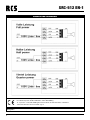
CONNECTION DIAGRAMS
Charge No.:
SRC-512 EN-1 / Loudspeaker for voice alarm systems
RCS Audio-Systems GmbH, Markfeld 5, 83043 Bad Aibiling
11 / System 1 / 1488, ITB Building Research Institute, 00-611 Warszawa, ul Filtrowa 1
1488-CPR-0181/W / EN-54-24:2008 / Typ A

SRC-512 EN-1
7
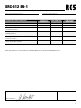
ESSENTIAL CHARACTERISTICS CHAPTER OF
STANDARD
PERFORMANCE HARMONISED
STANDARD
Performance in case of fire! 4.2, 5.2, 5.3, 5.4, 5.5 fulfilled EN 54-24:2008
Operation reliability 4.3, 4.4, 4.5, 5.6, 5.18 fulfilled EN 54-24:2008
Durability of operation
Temperature resistance
5.7, 5.8, 5.9 fulfilled EN 54-24:2008
Durability of operation
Humidity resistance
5.10, 5.11, 5.12 fulfilled EN 54-24:2008
Durability of operation
Corrosion resistance
5.13 fulfilled EN 54-24:2008
Durability of operation
Shock- and vibration resistance
5.14, 5.15, 5.16, 5.17 fulfilled EN 54-24:2008
DECLARED PERFORMANCE LEISTUNGSERKLÄRUNG
The performance of the product identified in points 1 and 2 is in conformity with the declared performance in point 9. This decla-
ration of performance is issued under the sole responsibility of the manufacturer identified in point 4.
Approved by (seal, signature): Date:
Technical Director:__________________________

SRC-512 EN-1
© Copyright by RCS AUDIO-SYSTEMS GmbH. Veröffentlichung und Vervielfältigung der enthaltenen Daten, auch auszugsweise, nur mit unserer Genehmigung.
RCS28.03.2019
-
 1
1
-
 2
2
-
 3
3
-
 4
4
-
 5
5
-
 6
6
-
 7
7
-
 8
8


in anderen Sprachen
- English: RCS SRC-512EN-1 Owner's manual
Verwandte Artikel
-
RCS SRC-106EN-1 Bedienungsanleitung
-
-
-
-
-
-
-
-
-