
Instructions
Pilot-controlled Dierential Pressure Controller PCVP
DN 100 - DN 250, PN 16 / PN 25
English Page2
Einbau-, Bedienungsanleitung
Hilfsgesteuerter Dierenzdruckregler PCVP
DN 100 - DN 250, PN 16 / PN 25
Deutsch Seite 16
73696670 DH-SMT/SI VI.JA.B2.5B © Danfoss 12/2006 1

2 VI.JA.B2.5B © Danfoss 12/2006 73696670 DH-SMT/SI
Instructions Pilot-controlled Dierential Pressure Controller PCVP
Table of Contents
1 Safety Notes ......................................................3
2 Denition of Application ............................3
3 Description .........................................................4
3.1 Construction ........................................................ 4
3.2 Mode of Operation ...........................................4
4 Technical Data ..................................................4
5 Scope of Delivery ................................... 5
6 Assembly ................................................ 6
6.1 Prior to Assembly ...............................................6
6.2 Installation Position, Installation Place ......6
6.3 When Installaling observe .............................. 6
6.4 Impulse Tube Installation ................................6
6.5 Insulation ..............................................................6
6.6 Installation Scheme ...........................................7
6.7 Assembly Drawings, Dimensions ................8
7 Start-up ................................................. 10
7.1 Required static Pressure, Pressure
Dierence .......................................................... 10
7.2 Leak and Pressure Test ................................... 10
7.3 Filling the System ............................................ 10
7.4 Star t-up ................................................................ 10
7.5 Putting out of Operation .............................. 10
7.6 Adjustment of the Dierential
Pressure ...............................................................11
7.7 Sealing .................................................................11
7.8 Function Test .....................................................12
8 Trouble Shooting ................................. 12
9 Replacement of Valve, Actuator,
Trims ..................................................... 13
9.1 Dismounting and Mounting
Actuator Valve ...................................................13
9.2 Replacement of Trim Valve VFG 2 ..............14
9.3 Dismounting, Mounting
Actuator AVP .....................................................14
9.4 Replacement of Trim Valve AVP ..................15

73696670 DH-SMT/SI VI.JA.B2.5B © Danfoss 12/2006 3
Instructions Pilot-controlled Dierential Pressure Controller PCVP
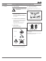
1 Safety Notes To avoid injury of persons
and damages to the device,
it is absolutely necessary to
carefully read and observe
these Instructions.
Necessary assembly, start-up, and maintenance
work may be performed only by qualied and
authorized personnel.
Please comply with the instructions of the
system manufacturer or system operator.
2 Denition of
Application
The controller is used for ow rate limitation of
water for heating, district heating and cooling
systems.
The admissible medium temperatures depend
on the design and comprise 5 - 140 °C, 5 - 150 °C,
5 - 200 °C.
The technical data on the rating plates deter-
mine the use.

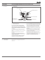
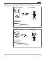
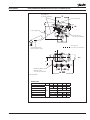
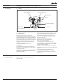
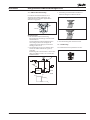
Pilot controller AVP
Throttling element
Valve unit PCV-VFG 2
Throttling valve
Throttling valve
only by DN150-250
4 VI.JA.B2.5B © Danfoss 12/2006 73696670 DH-SMT/SI
Instructions Pilot-controlled Dierential Pressure Controller PCVP
3 Description
3.2 Mode of Operation
The control unit consists of the PCV-VFG2
valve unit, installed in the main pipe, and the
dierential pressure controller AVP installed as
pilot controllers in the bypass. In the bypass line,
a throttle element is installed in front of the pilot
controllers.
The controller keeps the dierential pressure
across the corresponding section on a constant
level.
The valve and the pilot valves are pressure-
balanced.
The setpoint for the dierential pressure is
adjusted by pre-stressing the setpoint spring of
the pilot controller AVP.
The valve unit in the main pipe is opening on
rising pressure. The pilot controllers in the
bypass line are closing on rising pressure.
3.1 Construction
4 Technical Data Technical data, see rating plates and the PCV
data sheet.
In case of small ow rates, the valve in the main
pipe remains closed through the pressure spring
in the actuator of the valve unit. The pressure is
exclusively controlled by the pilot controller.
If the ow rate in the bypass is increased, the
pressure in the throttle element (Venturi nozzle)
decreases.
The reduced pressure acts through an impulse
tube upon the lower chamber of the actuator
of the valve unit. The main valve is thus opened
shock-free and continuously.
If the ow rate is reduced, the pressure in the
throttle element raises and the main valve closes.
This sequential switching guarantees an
operation free of vibrations and a small control
deviation over a wide positioning range.

73696670 DH-SMT/SI VI.JA.B2.5B © Danfoss 12/2006 5
Instructions Pilot-controlled Dierential Pressure Controller PCVP
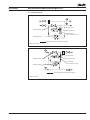
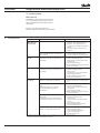
5 Scope of Delivery
DN 100 - DN 125
Assembly kit valve unit PCV-VFG 2 Pilot controller AVP DN 25
AVP
AVP
Cu pipe Ø 6 × 1 × 1500 mm
Cu pipe Ø 10 × 1 × 3000 mm
Throttling element
DN 150 - 250
Assembly kit valve unit PCV-VFG 21 Pilot controller AVP DN 40
Throttling element
Cu pipe Ø 6 × 1 × 1500 mm
Cu pipe Ø 10 × 1 × 3000 mm

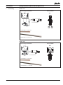
pin only
weld
do NOT
weld
1
2
6 VI.JA.B2.5B © Danfoss 12/2006 73696670 DH-SMT/SI
Instructions Pilot-controlled Dierential Pressure Controller PCVP
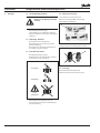
6 Assembly 6.1 Prior to Assembly:
Depressurized system before any
assembly work !
CAUTION!
• Cleanpipelinesystem.
• Installstrainerinfrontofthecontroller.
• Installshut-ounitsinfrontofandbehind
the controller.
6.2 Installation Position, Installation Place
• Installationisonlypermittedinhorizontal
pipelines with the actuators hanging in a
downward position.
• Thecontrollermaybeinstalledinthe
supply as well as in the return line.
6.3 When installing:
• Observedirectionofow.
• Designwithweldedends:
• Loadsonthevalvebodyandthethrottle
element by the pipes are not permitted.
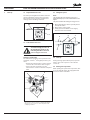
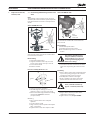
6.4 Impulse Tube Installation
See installation scheme, section 6.6.
For CU pipes Ø 10 × 1, insert sockets 1 on both
sides.
Care for correct position of the cutting rings 2.
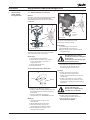
6.5 Insulation
The diaphragm actuators must not be insulated
when insulating system parts.

Valve unit PCV - VFG2
Pilot controller AVP
Throttling valve
Throttling element
Throttling valve
(only by DN 150 - 250)
lay impulse tube during mounting
Valve unit PCV - VFG2
Pilot controller AVP
Throttling valve
Throttling element
Throttling valve
(only by DN 150 - 250)
lay impulse tube during mounting
73696670 DH-SMT/SI VI.JA.B2.5B © Danfoss 12/2006 7
Instructions Pilot-controlled Dierential Pressure Controller PCVP
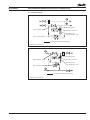
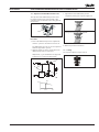
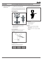
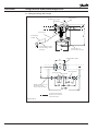
6.6 Installation Scheme
Installation in the Return Line
Installation in the Supply Line

DN 25: pipe Ø 33.7 × 3.2
Material: ST 35.8
(not part of the delivery)
DN 25 SW 50
Install impulse tubes
laterally because of dirt
Cu pipe Ø 10 × 1
Lay when assembling.
CU pipe Ø 6 × 1
Lay when assembling.
to the supply flow
to the return flow
Pilot controller AVP
Throttling
element
these parts are not in the scope of delivery
8 VI.JA.B2.5B © Danfoss 12/2006 73696670 DH-SMT/SI
Instructions Pilot-controlled Dierential Pressure Controller PCVP
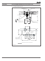
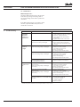
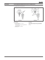
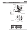
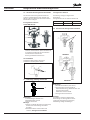
6.7 Assembly Drawings, Dimensions
DN 100 - 125

Install impulse tubes
laterally because of dirt
Cu pipe Ø 10 × 1
Lay when assembling.
CU pipe Ø 6 × 1
Lay when assembling.
to the supply ow
to the return ow
DN 40: pipe Ø 48.3 × 3.2
Material: ST 35.8
(not part of the delivery)
these parts are
not in the scope of delivery
73696670 DH-SMT/SI VI.JA.B2.5B © Danfoss 12/2006 9
Instructions Pilot-controlled Dierential Pressure Controller PCVP
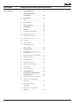
DN 150 - DN 250
Dimensions
Nominal diameter DN 100 125 150 200 250
L1
mm
350 400 480 600 730
H1 530 530 619 647 697
H2 - 174 229 254
D2 263 380
D1 250 350 385 500
B 200 210 310 336 412
A ≥ 290 320 350 410

5
4
2
3
8
67
9
1
p2 p1
10 VI.JA.B2.5B © Danfoss 12/2006 73696670 DH-SMT/SI
Instructions Pilot-controlled Dierential Pressure Controller PCVP
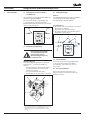
7 Start-up 7.1 Required Static Pressure
The static pressure p1 in front of the controller
must not fall below 1.5 bar (excess pressure).
Non-observance may lead to cavitation and
damages in the throttling element 1.
7.3 Filling the System
Note:
The controller 4 is closed when no pressure is
applied and only opens with a dened ow in the
bypass.
The pilot controller 5 is closing on rising pressure.
7.2 Leak and Pressure Tests
To avoid too high pressures at
the diaphragm actuators, the
following should be observed
prior to any pressure tests:
Actuator of valve unit:
The admissible operating excess pressure in the
actuator 2 is 25 bar
1)
. For higher pressures, you
must:
• Removetheimpulsetubes3attheactuator
and close the connections with a stopper.
• Priortoanyleakorpressuretest,the
instructions in section 7.3 must be complied
with.
1)
Pre-condition: Same pressure on both sides of the diaphragm.
If the pressure load is one-sided, the (+)diaphragm chamber
may have an excess pressure of 1 bar in comparison to the
(-)diaphragm chamber.
1. Open shut-o valves 6 that possibly exist in
the impulse tubes.
2. Open units 7 of the system.
3. Slowly open shut-o units in the supply
ow 8 and the return ow 9.
7.4 Start-up
During starting-up the lled system, open the
units in the same sequence as described in
section 7.3.
7.5 Putting out of operation
When putting the system out of operation, rst
close the shut-o units in the supply ow and
then those of the return ow.

1
P1
P2
3
2
7
PCVP
4
∆p
0 50% V
max
5
73696670 DH-SMT/SI VI.JA.B2.5B © Danfoss 12/2006 11
Instructions Pilot-controlled Dierential Pressure Controller PCVP
7.6 Adjustment of the Dierential Pressure
The setpoint of the dierential pressure must
be adjusted at the pilot controller AVP 1. The
setpoint range is indicated on the rating plate of
the actuator.
Procedure
1. Prior to the dierential pressure adjustment,
start the system as described in section 7.4.
The dierential pressure can also be adjusted
while the bypass 2 is opened.
2. Adjust the ow rate at the unit by which the
dierential pressure is controlled.
Adjustment, e.g. at unit 3 or 4 or via bypass 2
to approx. 50 % of the max. ow rate 5.
3. Adjustment of the dierential pressure
setpoint by turning the setpoint adjuster 6.
Turning to the right, increases the setpoint.
Turning to the left, reduces the setpoint.
4. Observe pressure indicators 7.
7.7 Sealing
The setpoint adjusters may be sealed.

12 VI.JA.B2.5B © Danfoss 12/2006 73696670 DH-SMT/SI
Instructions Pilot-controlled Dierential Pressure Controller PCVP
7.8 Function Test
Dierential pressure
Check the dierential pressure on the pressure
indicators by opening and closing a unit in
the corresponding section of the system to be
controlled.
If the dierential pressure is exceeded in either
direction, adjust the dierential pressure as
described in section 7.6.
8 Trouble Shooting
Fault Possible cause Remedy
Controller does
not hold the
dierential
pressure on a
constant level
Air in the actuators 1. Loosen impulse tube connections
at the actuators by approx. 1 rotation.
2. Deaerate, Caution hot water !
(move impulse tube until medium
penetrates).
3. Tighten impulse tube connections.
Impulse tubes or impulse tube
connections are dirty or damaged.
1. Remove impulse tube.
2. Clean impulse tubes and impulse
tube connections and check for free
passage.
Dierential
pressure is
too high
PilotvalveAVPdoesnotclose:
Valve seat or plug is dirty or damaged.
1. Remove impulse tube.
2. Dismount actutor and trim.
Procedure see section 9.4.
3. Clean seat and plug.
4. If damaged, replace trim or valve.
ValveVFG2doesnotclose:
Valve seat or plug is dirty or damaged.
1. Remove impulse tube.
2. Dismount actutor and trim
1)
.
Procedure, see section 9.2.
3. Clean seat and plug.
4. If damaged, replace trim or valve.
Rolling diaphragm in the actuator AVP
(pilot controller) is defective,
i.e. valve AVP does not close.
1. Remove impulse tube.
2. Replace actuator, see section 9.2.
Dierential
pressure is too
low
Valve plug of the pilot valve AVP
doesnotopen:
Valve seat or plug is dirty or damaged,
trim is dirty.
1. Remove impulse tube.
2. Dismount actuator and trim.
Procedure, see section 9.4.
3. Clean seat and plug.
4. If damaged, replace trim or valve.
Valve plug of the pilot valve VFG2
doesnotopen:
Valve seat or plug is dirty or damaged,
trim is dirty.
1. Remove impulse tube.
2. Dismount actutor and trim
1)
.
Procedure, see sections 9.1 and 9.2.
3. Clean seat and plug.
4. If damaged, replace trim or valve.
Rolling diaphragm in the actuator of the
valve unit is defective, i.e. valve VFG2 does
not open.
1. Remove impulse tube.
2. Loosen union nut SW 46
and remove actuator,
see also section 9.1.
3. Replace actuator.
1)
The trim can be replaced by qualied personnel up to DN 125.
From DN 150 replacement should be carried out by the Danfoss service personnel.

2
1
3
4
SW 46
5
grease
Cone
5
Turn
actuator
to the left
1
3
4
SW 46
73696670 DH-SMT/SI VI.JA.B2.5B © Danfoss 12/2006 13
Instructions Pilot-controlled Dierential Pressure Controller PCVP
9 Replacement of Valve,
Actuator, Trim
9.1 Dismounting and Mounting Actuator and
Valve
Note:
The springs 1 in the actuator are pre-stressed.
Therefore, the actuator must be pushed upwards
to be dismounted. You need a second person to
do this.
Valve unit DN 100 –125
Valve unit DN 150–250
Valve stem 3 and the stem of the actuator 4 are
not screwed to eachother.
Dismounting
1. Dismount impulse tubes.
2. Support actuator below or by a second
person as the springs 1 are pre-stressed.
3. Loosen union nut 2.
4. Remove actuator.
Prior to assembly check cone 5 !
1. Clean cone prior to mounting.
2. Check O rings for damages, in case of
damages, replace cone (see Spare Parts).
3. Grease cone with high-performance tting
component:BARRIERTAL55/3HV
(see Spare Parts).
Mounting
1. Place actuator at the valve and push
upwards.
2. Screw on union nut 2.
3. Align actuator, observe position of impulse
tube connections.
4. Tighten union nut 1, max. torque 100 Nm.
The stem of the actuator 4 is screwed into the
valve stem 3.
Dismounting
1. Dismount impulse tubes.
2. Completely loosen union nut 1.
The actuator hangs on the screwed-in
stem 4.
The actuator weights approx.
20 kg. In addition, an internal
spring package is pre-stressed.
Secure against dropping down
before unscrewing.
3. Screw the stem of the actuators 4 out of the
valve stem 3 by turning the actuator to the
left.
Mounting
1. Place actuator at the valve and push upward
to press the spring package in the actuator
together (second person necessary).
2. Carefully turn actuator to the right.
By this, carefully screw in the stem of the
actuator into the valve stem to its stop.
Then, return the actuator by
approx. 1 rotation (to the left)
3. Align actuator, observe position of the
control lines connections.
4. Tighten union nut 1, torque 100 Nm.

2
3
1
4
5
6
1
14 VI.JA.B2.5B © Danfoss 12/2006 73696670 DH-SMT/SI
Instructions Pilot-controlled Dierential Pressure Controller PCVP
9 Replacement of Valve,
Actuator, Trim
9.2 Replacement of Trim Valve VFG2
The trim can be replaced by qualied personnel
up to DN 125. From DN 150 replacement should
be carried out by the Danfoss service personnel.
Removing the trim:
Valves DN 100–125
1. Dismount actuator 1 (see section 9.1).
2. Unscrew hexagon head cap screw 2.
3. Remove bonnet 3.
4. Take out trim 4.
Prior to installation:
Clean sealing surfaces 5 and socket 6, grease
sealing surfaces with antiseize graphite
petroleum.
Installing the trim:
Mounitng is carried out in reverse order.
Torque hexagon head cap screws 2:
DN Torque Wrench
100 - 125 180 Nm SW 30
9.3 Dismounting, Mounting Actuator AVP
Dismounting
1. Dismount impulse tubes.
2. Loosen union nut 1.
3. Remove actuator.
Mounting
1. Place actuator at the valve and align,
observe position of the impulse tube
connections.
2. Screw on union nut 1 and tighten, torque
100 Nm.
AVP

2
2
73696670 DH-SMT/SI VI.JA.B2.5B © Danfoss 12/2006 15
Instructions Pilot-controlled Dierential Pressure Controller PCVP
9.4 Replacement of Trim Valve AVP
AVP DN 25 AVP DN 40
Dismounting
1. Unscrew actuator (see above).
2. Unscrew trim 2.
DN25:withpipetongs,wrapgumstrips
around the trim
DN40:withwrenchSW55
3. Pull out trim.
Mounting
Mounting is carried out in reverse order. Only
tighten with low torque, sealing is made with
O rings.

16 VI.JA.B2.5B © Danfoss 12/2006 73696670 DH-SMT/SI
Inhaltsverzeichnis 1 Sicherheitshinweise ...................................17
2 Bestimmungsgemäße
Verwendung ................................................... 17
3 Beschreibung ................................................. 18
3.1 Aufbau .................................................................18
3.2 Wirkungsweise .................................................18
4 Technische Daten .........................................18
5 Lieferumfang .................................................19
6 Montage ...........................................................20
6.1 Vor der Montage beachten ......................... 20
6.2 Einbaulage,Einbauort .................................. 20
6.3 BeimEinbaubeachten .................................. 20
6.4 EinbauSteuerleitung ..................................... 20
6.5 Isolierung ........................................................... 20
6.6 Einbauschemas ..................................................21
6.7 Montagezeichnungen,
Abmessungen .................................................. 22
7 Inbetriebnahme ............................................24
7.1 Erforderliche(r)statischerDruck,
Druckdierenz .................................................. 24
7.2 Dichtheitsprüfung / Druckprüfung ......... 24
7.3 Füllung der Anlage ......................................... 24
7.4 Inbetriebnahme .............................................. 24
7.5 Ausserbetriebnahme ..................................... 24
7.6 Dierenzdruckeinstellung ........................... 25
7.7 Plombierung ..................................................... 25
7.8 Funktionsprüfung .......................................... 26
8 Störungshinweise ........................................ 26
9 Austausch von Ventil, Antrieb,
Innengarnituren ........................................... 27
9.1 Antrieb demontieren, montieren ............. 27
9.2 Austausch der Innengarnitur
Ventil VFG 2 ....................................................... 28
9.3 Demontage, Montage
Antrieb AVP ....................................................... 28
9.4 Austausch der Innengarnitur
Ventil AVP .......................................................... 28
Instructions Hilfsgesteuerter Dierenzdruckregler PCVP

73696670 DH-SMT/SI VI.JA.B2.5B © Danfoss 12/2006 17
1 Sicherheitshinweise Um Verletzungen an Personen
und Schäden am Gerät zu
vermeiden, dies Anleitung
unbedingt beachten.
Montage, Inbetriebnahme und
Wartungsarbeiten dürfen nur von sachkundigen
und autorisierten Personen durchgeführt
werden.
Die Vorgaben des Anlagenherstellers und
Anlagenbetreibers sind zu beachten.
2 Bestimmungsgemäße
Verwendung
Der Regler dient der Dierenzdruckregelung in
Heizungs-, Fernwärmeheizungs- und Kühlan-
lagen für das Medium Wasser. Die zulässigen
Mediumstemperaturen sind je nach Ausführung
5 - 140 °C, 5 - 150 °C, 5 - 200 °C.
Die technischen Daten auf den Typenschildern
sind für die Verwendung maßgebend.
Instructions Hilfsgesteuerter Dierenzdruckregler PCVP

Pilotregler AVPDrosselelement DE
Stellgerät PCV-VFG2
Hauptleitung
Bypass
Drosselventil
Drosselventil
nur bei DN150-250
18 VI.JA.B2.5B © Danfoss 12/2006 73696670 DH-SMT/SI
3 Beschreibung
3.2 Wirkungsweise
Die Regeleinheit besteht aus dem in der
Hauptleitung eingebauten Stellgerät PCV-VFG2
und dem im Bypass als Pilotregler angeordneten
Dierenzdruckregler AVP. In der Bypassleitung ist
vor dem Pilotregler ein Drosselement eingebaut.
Der Regler hält den Dierenzdruck über der
Anlagenstrecke konstant entsprechend dem
eingestellten Sollwert.
Das Stellventil und das Pilotventil ist
druckentlastet.
Die Sollwerteinstellung des Dierenzdruckes
erfolgt über die Vorspannung der Sollwertfeder
des Pilotreglers AVP.
Das Stellgerät in der Hauptleitung ist drucklos
geschlossen. Der Pilotregler in der Bypassleitung
ist drucklos geönet.
3.1 Aufbau
4 Technische Daten Technische Daten siehe Typenschilder und
Datenblatt PCV.
Bei geringen Volumenströmen bleibt das Ventil
in der Hauptleitung durch die Druckfeder
im Antrieb des Stellgerätes geschlossen. Die
Dierenzdruckregelung erfolgt ausschließlich
über den Pilotregler.
ErhöhtsichderVolumenstrominder
Bypassleitung, so sinkt der Druck im
Drosselelement (Venturidüse).
Dieser abgesenkte Druck wirkt über eine
Steuerleitung auf die Unterkammer des Antriebs
des Stellgerätes. Das Hauptventil wird dadurch
stoßfrei und stetig geönet.
Reduziert sich der Volumenstrom, so steigt der
Druck im Drosselelement an und das Hauptventil
schließt.
Diese Folgeschaltung gewährleistet eine
schwingungsfreie Betriebsweise und eine
geringe Regelabweichung über einen großen
Stellbereich.
Instructions Hilfsgesteuerter Dierenzdruckregler PCVP

73696670 DH-SMT/SI VI.JA.B2.5B © Danfoss 12/2006 19
5 Lieferumfang
DN 100 - 125
Bausatz Stellgerät PCV-VFG2 Pilotregler DN 25
AVP
AVP
Cu-Rohr Ø 6 × 1 × 1500 mm
Cu-Rohr Ø 10 × 1 × 3000 mm
Drosselelement
DN 150 - 250
Bausatz Stellgerät PCV-VFG2 Pilotregler DN 40
Drosselelement
Cu-Rohr Ø 6 × 1 × 1500 mm
Cu-Rohr Ø 10 × 1 × 3000 mm
Instructions Hilfsgesteuerter Dierenzdruckregler PCVP

nur Heften
Schweißen
nicht
Schweißen
1
2
20 VI.JA.B2.5B © Danfoss 12/2006 73696670 DH-SMT/SI
6 Montage 6.1 Vor der Montage beachten
Anlage vor der Montage drucklos
machen!
Achtung!
• Rohrleitungssystemreinigen
• SchmutzfängervordemReglereinbauen
• AbsperrarmaturenvorundnachdemRegler
einbauen
6.2 Einbaulage, Einbauort
• DerEinbauistnurinwaagrechte
Rohrleitung mit nach unten hängenden
Antrieben zulässig.
• DerReglerkannimVorlaufoderRücklauf
der Anlage eingebaut werden
6.3 Beim Einbau beachten
• Durchussrichtungbeachten
• AusführungmitAnschweißendenelement
by the pipes are not permitted.
• BelastungderVentilgehäuseunddes
Drosselelementes durch die Rohrleitungen
sind nicht zulässig.
6.4 Einbau Steuerleitung
SieheEinbauschemaAbschnitt6.6
Bei den CU-Leitungen Ø10 ×1 beidseitig
Einsteckhülsen1 einfügen.
Richtige Lage der Schneidringe 2 beachten
6.5 Isolierung
Bei Isoliermaßnahmen dürfen die
Membranantriebe nicht isoliert werden.
Instructions Hilfsgesteuerter Dierenzdruckregler PCVP
Seite wird geladen ...
Seite wird geladen ...
Seite wird geladen ...
Seite wird geladen ...
Seite wird geladen ...
Seite wird geladen ...
Seite wird geladen ...
Seite wird geladen ...
-
 1
1
-
 2
2
-
 3
3
-
 4
4
-
 5
5
-
 6
6
-
 7
7
-
 8
8
-
 9
9
-
 10
10
-
 11
11
-
 12
12
-
 13
13
-
 14
14
-
 15
15
-
 16
16
-
 17
17
-
 18
18
-
 19
19
-
 20
20
-
 21
21
-
 22
22
-
 23
23
-
 24
24
-
 25
25
-
 26
26
-
 27
27
-
 28
28


in anderen Sprachen
- English: Danfoss PCVP Operating instructions
Verwandte Artikel
-
Danfoss PCVP Bedienungsanleitung
-
-
-
-
-
-
-
-
-