SBC In-wall mounting kit for 5.7''MB Bedienungsanleitung
- Typ
- Bedienungsanleitung

Saia-Burgess Controls Ltd.
Bahnhofstrasse 18 I CH-3280 Murten I Switzerland
T +41 (0)26 672 71 11 I F +41 (0)26 672 74 99 l www.start-controls.com
Manual in-wall kit for 5.7 MB panels 26- 863_E-D-F.doc Subject to change without notice Page 1 / 25
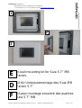
In-wall mounting kit for Saia 5.7’’ MB
Panels.
Kit für Unterputzmontage des Saia MB
Panels 5.7"
Kit pour montage encastré des pupitres
Saia 5.7’’ MB.
E
D
F
1
3
2

Saia-Burgess Controls Ltd.
Bahnhofstrasse 18 I CH-3280 Murten I Switzerland
T +41 (0)26 672 71 11 I F +41 (0)26 672 74 99 l www.start-controls.com
Manual in-wall kit for 5.7 MB panels 26- 863_E-D-F.doc Subject to change without notice Page 2 / 25
The in-wall mounting kit for building the PCD7.D457-IWS into a solid wall comprises:
Quantity Name
1 Complete built-in box with 4 screwed columns
1 Metallic frame
4 Metric M 4 screw
1 Complete front face
The in-wall mounting kit for solid wall insertion does not include the fixing set for Cavity
(hollow) walls. This is delivered separately under reference 4 121 4910 0
Instruction manual: page 3 to page 9
*******************************************************
Das PCD7.D457-IWS Montageset für den Einbau in Vollwänden besteht aus:
Anzahl Bezeichnung
1 Einbaugehäuse mit 4 Schraublöchern
1 Metallrahmen
4 metrische M 4- Schrauben
1 Komplette Vorderseite
Im Montageset für den Einbau an „Vollwänden“ ist das zusätzliche Befestigungsset für
„Hohlwände“, das mit der Referenz 4 121 4910 0 separat geliefert wird, nicht enthalten.
Die Betreibsanleitung: Seite 11 bis 17
*******************************************************
Le Kit pour montage encastré en mur plein PCD7.D457-IWS se compose de :
Quantité Désignation
1 Boîtier d’encastrement complet avec 4 colonnes vissées
1 Cadre métallique
4 Vis métrique M 4
1 Face frontale complète
Le Kit pour montage encastré en « mur plein » ne comprend pas le set de fixation
additionnel pour « mur creux » qui est livré séparément sous la référence 4 121 4910 0
Manuel d’instruction: page 19 à 25
E
D
F

Saia-Burgess Controls Ltd.
Bahnhofstrasse 18 I CH-3280 Murten I Switzerland
T +41 (0)26 672 71 11 I F +41 (0)26 672 74 99 l www.start-controls.com
Manual in-wall kit for 5.7 MB panels 26- 863_E-D-F.doc Subject to change without notice Page 3 / 25
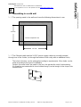
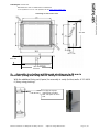
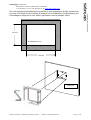
1 - Assembling in a solid wall
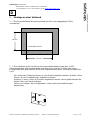
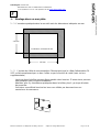
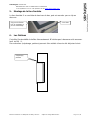
1 – 1 The opening made in the wall must have the following dimensions in mm.
1 – 2 The Ethernet cable and the 24 VDC power supply cable are normally inserted
through one of the 4 sides (or through the bottom of the cavity with an additional hole)
The holes in the box can be enlarged according to requirements. More holes can be
made according to the type of installation.
Caution: the more holes are made in the box, the greater the risk of dust entering.
It is therefore recommended to insert rubber bungs (can be bought in the shops) into
unused holes.
235 mm
210 mm
Minimum depth 65 mm
E

Saia-Burgess Controls Ltd.
Bahnhofstrasse 18 I CH-3280 Murten I Switzerland
T +41 (0)26 672 71 11 I F +41 (0)26 672 74 99 l www.start-controls.com
Manual in-wall kit for 5.7 MB panels 26- 863_E-D-F.doc Subject to change without notice Page 4 / 25
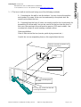
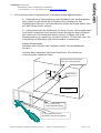
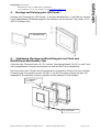
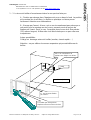
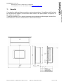
1 – 3 The box is built-in into the wall using one of the following methods:
A – Screwing into the wall or into the bottom. You can choose the position
and number of screws. Holes can be made easily in the plastic box. Be
careful not to distort the box.
B – Screwing from the front: 4 holes not usually used for this (used mainly for
assembling in hollow walls) but can be used to fix the box from the front. In
this case, the opening in the wall must be precise (235 max in width). Use
countersunk screws to avoid creating a raised surface.
Other possibilities:
Glue or filler around the box (mortar, quick-drying cement etc.)
Careful: do not use expanding foam as this might distort the box.
Solid wall
Cavit
y
B - 4 holes for fixing from
the front
A- Fixing with screws into the wall
or through the bottom.
Info: the console connectors are
pointing downwards.

Saia-Burgess Controls Ltd.
Bahnhofstrasse 18 I CH-3280 Murten I Switzerland
T +41 (0)26 672 71 11 I F +41 (0)26 672 74 99 l www.start-controls.com
Manual in-wall kit for 5.7 MB panels 26- 863_E-D-F.doc Subject to change without notice Page 5 / 25
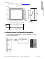
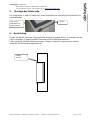
2 - Assembly in a hollow wall through pinching up to 30 mm in
thickness (using the fixing set for cavity or hollow walls!)
With the additional fixing set (4 parts) for assembly in cavity (hollow) walls: 4 121 4910
0 (fixing using pinching).
Fix (clip) the 4 parts
yourself into a hollow
wall. Two parts on each
side.
232 mm
207 mm
63.5 mm
Drawing of the
built
-
in
box

Saia-Burgess Controls Ltd.
Bahnhofstrasse 18 I CH-3280 Murten I Switzerland
T +41 (0)26 672 71 11 I F +41 (0)26 672 74 99 l www.start-controls.com
Manual in-wall kit for 5.7 MB panels 26- 863_E-D-F.doc Subject to change without notice Page 6 / 25
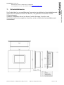
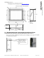
The opening made in the wall must have the dimensions indicated in mm. Careful: the
broad version is different from the hollow wall version. Tightening by pinching is done
using 4 Allen keys pointing forwards.
255 mm
210 mm
Depth minimum 65 mm
Hollow wall

Saia-Burgess Controls Ltd.
Bahnhofstrasse 18 I CH-3280 Murten I Switzerland
T +41 (0)26 672 71 11 I F +41 (0)26 672 74 99 l www.start-controls.com
Manual in-wall kit for 5.7 MB panels 26- 863_E-D-F.doc Subject to change without notice Page 7 / 25
3 - Assembling and fixing the “MB panel”
Assemble and fix the “MB panel” 2 onto the metal frame 1 using the 4 fixing elements
delivered with the console. If you misplace this, the reference is 4 109 4881 0 (set of 4
parts).
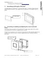
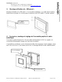
4 - Connecting, assembling and adjusting the console and metal
frame.
Connect the Ethernet cable (RJ 45) and the 24 VDC power supply cable to the console
(the orange power connector is supplied with the console).
All parts are to be placed on the 4 columns of the built-in box. After adjusting, tighten the 4
screws in each of the 4 corners 3 (screws supplied with the kit). It will be set firmly in
place later.
3
4 metric screws
4
Front
1
Metal frame

Saia-Burgess Controls Ltd.
Bahnhofstrasse 18 I CH-3280 Murten I Switzerland
T +41 (0)26 672 71 11 I F +41 (0)26 672 74 99 l www.start-controls.com
Manual in-wall kit for 5.7 MB panels 26- 863_E-D-F.doc Subject to change without notice Page 8 / 25
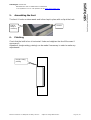
5 - Assembling the front
The front 4 hooks on downwards and is then kept in place with a clip at the back.
6 - Finishing
Check that the built-in box is horizontal. Undo and retighten the four M4 screws if
necessary3.
Alterations (roughcasting, paining) can be made if necessary in order to make any
adjustments.
Rough-casting,
painting
Clip for
fixing or
removing
4 hooks

Saia-Burgess Controls Ltd.
Bahnhofstrasse 18 I CH-3280 Murten I Switzerland
T +41 (0)26 672 71 11 I F +41 (0)26 672 74 99 l www.start-controls.com
Manual in-wall kit for 5.7 MB panels 26- 863_E-D-F.doc Subject to change without notice Page 9 / 25
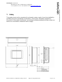
7 - Safety
This product must not be connected to a domestic mains supply. It must be installed by
qualified personnel (knowledge of standards, current rules and safety regulations).
Any work on this product (assembly, connecting and disassembling) must be carried out
whilst not connected to a domestic mains supply.

Saia-Burgess Controls Ltd.
Bahnhofstrasse 18 I CH-3280 Murten I Switzerland
T +41 (0)26 672 71 11 I F +41 (0)26 672 74 99 l www.start-controls.com
Manual in-wall kit for 5.7 MB panels 26- 863_E-D-F.doc Subject to change without notice Page 10 / 25

Saia-Burgess Controls Ltd.
Bahnhofstrasse 18 I CH-3280 Murten I Switzerland
T +41 (0)26 672 71 11 I F +41 (0)26 672 74 99 l www.start-controls.com
Manual in-wall kit for 5.7 MB panels 26- 863_E-D-F.doc Subject to change without notice Page 11 / 25
1 -
Montage an einer Vollwand
1 – 1 Die vorzunehmende Wandaussparung hat die in mm angegebene Größe
vorzuweisen.
1 – 2 Der Kabeleinzug für das Ethernet-Kommunikationskabel sowie das 24 VDC
Versorgungskabel wird normalerweise entweder durch eine der 4 Seiten oder durch
Einzug hinter dem geschaffenen Hohlraum vorgenommen(Hinten: mit einem zusätzlichen
Loch).
Die Löcher des Gehäuses können je nach Bedarf vergrößert werden. Weitere Löcher
können, je nach Installationsart, angebracht werden.
Achtung: Je mehr Löcher im Gehäuse angebracht werden, desto größer besteht die
Gefahr, dass sich Staub einlagert.
Daher ist es ratsam, die nicht genutzten Löcher mit Kautschukdichtungen
abzudichten.
235 mm
210 mm
Mindesttiefe 65 mm
D

Saia-Burgess Controls Ltd.
Bahnhofstrasse 18 I CH-3280 Murten I Switzerland
T +41 (0)26 672 71 11 I F +41 (0)26 672 74 99 l www.start-controls.com
Manual in-wall kit for 5.7 MB panels 26- 863_E-D-F.doc Subject to change without notice Page 12 / 25
1 – 3 Die Anbringung des Einbaugehäuses in der Wand erfolgt folgendermaßen:
A – Fixierung durch Verschraubung in der Wanddicke oder am Wandboden.
Die Position und die Anzahl der Schrauben kann beliebig sein. Das
Plastikgehäuse lässt sich leicht durchbohren.Achten Sie hierbei darauf, dass
sich das Gehäuse nicht verformt.
B – Verschraubung an der Vorderseite, an den 4 Löchern, die normalerweise
nicht hierfür vorgesehen sind, die aber bei der Montage an einer Hohlwand,
der Fixierung an der Vorderseite dienen können. In diesem Fall ist die
Wandaussparung zu präzisieren (sie darf höchstens 235 mm breit sein). Zur
Vermeidung von Überdicke sind Senkschrauben zu verwenden.
Weitere Möglichkeiten:
Anbinden oder Andichten des Gehäuses (Mörtel, schnellabbindender
Zement…)
Achtung: Bitte verwenden Sie keinen Bauschaum. Dies könnte zur
Verformung des Gehäuses führen.
Vollwand
Aushöhlung
B - 4 Löcher für die
Vorderseitenbefestigung
A - Schraubfixierung in der
Wanddicke oder am Wandboden
Info: Die Stecker der Panels
sind nach unten gerichtet.

Saia-Burgess Controls Ltd.
Bahnhofstrasse 18 I CH-3280 Murten I Switzerland
T +41 (0)26 672 71 11 I F +41 (0)26 672 74 99 l www.start-controls.com
Manual in-wall kit for 5.7 MB panels 26- 863_E-D-F.doc Subject to change without notice Page 13 / 25
2 - Montage an einer bis zu 30 mm dicken Hohlwand mit
Klemmträgern (mit dem Befestigungsset für Hohlwände!)
Mit dem zusätzlichen Befestigungsset (4 Teile) für Hohlwände: 4 121 4910 0
(Fixierung mit Klemmträgern)
232 mm
207 mm
63.5 mm
Zeichnung des Einbaugehäuses
Bringen Sie selbst die 4
Befestigungsteile für
„Hohlwände“ an, zwei
Teile pro Seite. (Klipps)

Saia-Burgess Controls Ltd.
Bahnhofstrasse 18 I CH-3280 Murten I Switzerland
T +41 (0)26 672 71 11 I F +41 (0)26 672 74 99 l www.start-controls.com
Manual in-wall kit for 5.7 MB panels 26- 863_E-D-F.doc Subject to change without notice Page 14 / 25
Die vorzunehmende Wandaussparung hat die in mm angegebene Größe vorzuweisen.
Achtung: Die Breite für die Variante „Hohlwand“ ist nicht dieselbe. Die Befestigung mit
Klemmträgern erfolgt mit 4 nach Außen gerichteten Inbusschrauben (Allen).
255 mm
210 mm
Mindesttiefe 65 mm
Hohlwand

Saia-Burgess Controls Ltd.
Bahnhofstrasse 18 I CH-3280 Murten I Switzerland
T +41 (0)26 672 71 11 I F +41 (0)26 672 74 99 l www.start-controls.com
Manual in-wall kit for 5.7 MB panels 26- 863_E-D-F.doc Subject to change without notice Page 15 / 25
4 - Montage und Fixierung des „MB-Panels“
Montage und Fixierung des „MB-Panels“ 2 auf dem Metallrahmen 1 mit Hilfe der mit dem
Panel mitgelieferten 4 Befestigungsteile. Die Referenz (bei Verlust der Teile) lautet 4 109
4881 0 (4-teiliges Set).
4 - Verbindung, Montage und Einstellung des aus Panel und
Metallrahmen bestehenden Sets
Verbinden des Ethernet-Kabels (RJ 45) und des Versorgungskabels 24 VDC an das Panel
(der orangefarbene Stromversorgungsstecker wird mit dem Panel mitgeliefert).
Das Set wird an den 4 Enden des Einbaugehäuses angebracht. Ziehen Sie nach erfolgter
Einstellung die 4 Schrauben an den 4 Ecken 3 an (die Schrauben werden mit dem Set
mitgeliefert). Die definitive Fixierung erfolgt in einem weiteren Schritt erfolgen.
3
4 metrische
Schrauben
4
Vorderseite
1
Metallrahmen

Saia-Burgess Controls Ltd.
Bahnhofstrasse 18 I CH-3280 Murten I Switzerland
T +41 (0)26 672 71 11 I F +41 (0)26 672 74 99 l www.start-controls.com
Manual in-wall kit for 5.7 MB panels 26- 863_E-D-F.doc Subject to change without notice Page 16 / 25
5 - Montage der Vorderseite
Die Vorderseite 4 wird von oben nach unten eingehakt und anschließend mit einem Clip
unten befestigt.
6 - Ausrichtung
Achten Sie darauf, dass das Einbaugehäuse waagrecht angebracht ist. Schrauben Sie die
4 M4-Schrauben 3 gegebenenfalls erneut ab und anschließend wieder an.
Falls notwendig, können Nachbesserungen (Verputz, Anstrich) vorgenommen werden,
damit das Panel korrekt ausgerichtet ist.
Verputz,
Anstrich
Clip, um zu
befestigen und
wegzunehmen.
4 Haken

Saia-Burgess Controls Ltd.
Bahnhofstrasse 18 I CH-3280 Murten I Switzerland
T +41 (0)26 672 71 11 I F +41 (0)26 672 74 99 l www.start-controls.com
Manual in-wall kit for 5.7 MB panels 26- 863_E-D-F.doc Subject to change without notice Page 17 / 25
7 - Sicherheitshinweise
Das Produkt darf nur von qualifiziertem Personal an das elektrische Hausinstallationsnetz
angeschlossen werden (Kenntnis der Normen, der geltenden Vorschriften und der
Sicherheitsregeln).
Sämtliche Tätigkeiten mit und an diesem Produkt (Montage, Anschluss und
Abmontierung) sind ohne jeglichen Anschluss an das elektrische Hausinstallationsnetz
vorzunehmen.

Saia-Burgess Controls Ltd.
Bahnhofstrasse 18 I CH-3280 Murten I Switzerland
T +41 (0)26 672 71 11 I F +41 (0)26 672 74 99 l www.start-controls.com
Manual in-wall kit for 5.7 MB panels 26- 863_E-D-F.doc Subject to change without notice Page 18 / 25

Saia-Burgess Controls Ltd.
Bahnhofstrasse 18 I CH-3280 Murten I Switzerland
T +41 (0)26 672 71 11 I F +41 (0)26 672 74 99 l www.start-controls.com
Manual in-wall kit for 5.7 MB panels 26- 863_E-D-F.doc Subject to change without notice Page 19 / 25
1 - Montage dans un mur plein.
1 – 1 L’ouverture pratiquée dans le mur doit avoir les dimensions indiquées en mm.
1 – 2 L’arrivée du câble de communication Ethernet ainsi que le câble d’alimentation 24
VDC se fait normalement par un des 4 côtés ou par le fond de la cavité (avec un trou
supplémentaire)
Les trous dans le boîtier peuvent être agrandis selon besoins. D’autres trous peuvent
être pratiqués selon le type d’installation.
Attention: plus il y d’ouvertures pratiquées dans le boîtier, plus il y a risque d’entrée
de poussière.
Il est donc conseillé de boucher les trous non utilisés par des manchons en
caoutchouc du commerce.
235 mm
210 mm
Profondeur minimum 65 mm
F

Saia-Burgess Controls Ltd.
Bahnhofstrasse 18 I CH-3280 Murten I Switzerland
T +41 (0)26 672 71 11 I F +41 (0)26 672 74 99 l www.start-controls.com
Manual in-wall kit for 5.7 MB panels 26- 863_E-D-F.doc Subject to change without notice Page 20 / 25
1 – 3 La tenue du boîtier d’encastrement dans le mur peut se faire par:
A - Fixation par vissage dans l’épaisseur du mur ou dans le fond La position
et le nombre de vis est libre. Le boîtier en plastique se laisse percer
facilement. Attention aux déformations.
B - Vissage par l’avant : 4 trous, qui ne sont normalement pas prévus pour
cela mais pour le montage en mur creux, peuvent servir de moyen de
fixation par l’avant. Dans ce cas, l’ouverture dans le mur doit être précise
(235 max en largeur). Utiliser des vis à tête fraisée pour ne pas créer une
surépaisseur
Autres possibilités :
Collage ou bourrage autour du boîtier (mortier, ciment rapide …)
Attention : ne pas utiliser de mousse expansive qui pourrait déformer le
boîtier.
Cloison pleine
Cavité
B - 4 trous pour fixation
par l’avant
A- Fixation par vissage dans
l’épaisseur du mur ou dans le fond.
Info : Les connecteurs du
pupitre sons dirigés vers le bas.
Seite wird geladen ...
Seite wird geladen ...
Seite wird geladen ...
Seite wird geladen ...
Seite wird geladen ...
-
 1
1
-
 2
2
-
 3
3
-
 4
4
-
 5
5
-
 6
6
-
 7
7
-
 8
8
-
 9
9
-
 10
10
-
 11
11
-
 12
12
-
 13
13
-
 14
14
-
 15
15
-
 16
16
-
 17
17
-
 18
18
-
 19
19
-
 20
20
-
 21
21
-
 22
22
-
 23
23
-
 24
24
-
 25
25


SBC In-wall mounting kit for 5.7''MB Bedienungsanleitung
- Typ
- Bedienungsanleitung
in anderen Sprachen
Verwandte Artikel
-
SBC In-wall-kits for 5,7"/7", 10.4" & 12.1" MB-Panels Bedienungsanleitung
-
-
-
-
-
-
-
-
SBC Wall mounting set for Web Panels CE&eXP Bedienungsanleitung
-